Subscribe to Our Youtube Channel
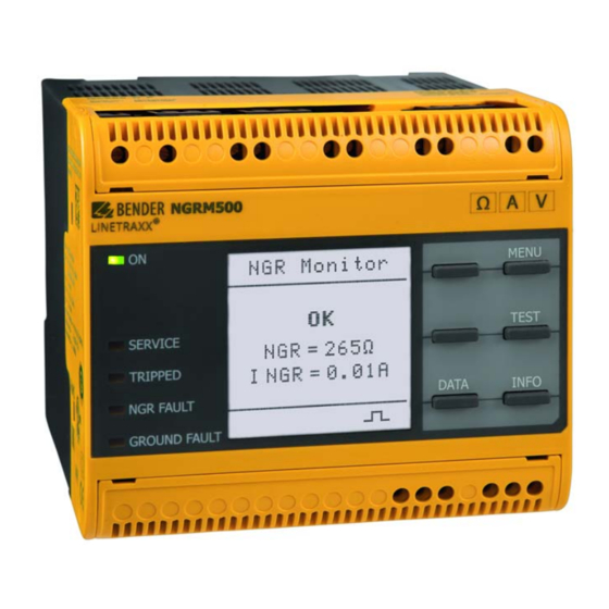
Summary of Contents for Bender NGRM500
- Page 1 NGRM500 (HRG) NGRM550 (LRG) Neutral Grounding Resistor Monitor (NGR) NGRM5xx_D00373_08_Q_XXEN/11.2022 Quick-start guide EN...
-
Page 2: Intended Use
NGRM500 (HRG), NGRM550 (LRG) Intended use Safety instructions The NGRM500 is only intended for use in high-resistance of electrocution due to electric shock! grounded systems. The NGRM550 is only intended for Touching live parts of the system carries the risk of: use in low-resistance grounded systems. -
Page 3: Star Configuration
NGRM500 (HRG), NGRM550 (LRG) Connection X1 Digital 1 (configurable: pulser, NGR method) Reset IN Test IN Modbus RTU (A) Modbus RTU (B) Common Analog output Open collector: Pulser OUT Open collector: Device health Output for supply of external relays (+24 V, max. 100 mA) - Page 4 NGRM500 (HRG), NGRM550 (LRG) Measuring current transformer selection Depending on the system to be monitored, a suitable measuring current transformer has to be chosen. All common measuring current transformers (50 mA or 5 A on the secondary side) can be used. The following table helps you with...
-
Page 5: Menu Overview
NGRM500 (HRG), NGRM550 (LRG) Menu overview 1. Data meas. values , Method, R NGR rel sense, rms rel rms rel, fund fund rel fund fund rel, harm harm rel harm harm rel, 2. Harmonics 3. History History, Delete 4. Pulser... -
Page 6: Initial Commissioning
NGRM500 (HRG), NGRM550 (LRG) HRG system: Recommended minimum value () = Limited temperature range at any field calibration tem- (tripping level 50 %) perature ±20 K The temperatures must be within the limits of the operating Temperature range –40…+60 °C, temperature range of –40…+70 °C... -
Page 7: Initial Measurement
NGRM500 (HRG), NGRM550 (LRG) 2. System settings of the relays (menu 6.5) 5. Initial measurement The factory setting for the relays is fail-safe. In the case of During device start, all measured values are recorded. a test, the relays change state. -
Page 8: Technical Data
NGRM500 (HRG), NGRM550 (LRG) Technical data Menu Factory settings Rated voltage ..................250 V Menu 6.5: System settings Overvoltage category ................III Nominal supply voltage U ..........AC/DC, 48…240 V Mode: Fail-safe 1. Ground-fault relay for UL applications .............AC/DC, 48…240 V Rel.


Need help?
Do you have a question about the NGRM500 and is the answer not in the manual?
Questions and answers