User Manuals: Bender NGRM700 Grounding Resistor Monitor
Manuals and User Guides for Bender NGRM700 Grounding Resistor Monitor. We have 7 Bender NGRM700 Grounding Resistor Monitor manuals available for free PDF download: Manual, Quick Start Manual

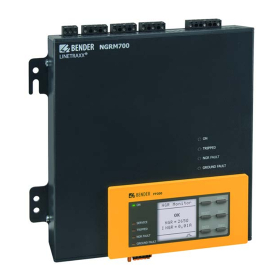
Bender NGRM700 Manual (80 pages)
Neutral Grounding Resistor Monitor
Brand: Bender
|
Category: Measuring Instruments
|
Size: 5 MB
Table of Contents
Advertisement

Bender NGRM700 Manual (80 pages)
Neutral Grounding Resistor Monitor
Brand: Bender
|
Category: Measuring Instruments
|
Size: 5 MB
Table of Contents

Bender NGRM700 Manual (64 pages)
Neutral Grounding Resistor Monitor
Brand: Bender
|
Category: Measuring Instruments
|
Size: 1 MB
Table of Contents
Advertisement

Bender NGRM700 Manual (9 pages)
Neutral grounding resistor monitor
Brand: Bender
|
Category: Measuring Instruments
|
Size: 1 MB
Table of Contents

Bender NGRM700 Quick Start Manual (9 pages)
Neutral Grounding Resistor Monitor (NGR)
Table of Contents

Bender NGRM700 Quick Start Manual (8 pages)
Neutral Grounding Resistor Monitor
Brand: Bender
|
Category: Measuring Instruments
|
Size: 1 MB
Table of Contents

Bender NGRM700 Quick Start Manual (8 pages)
NGR monitor
Brand: Bender
|
Category: Measuring Instruments
|
Size: 1 MB