Chapters
Table of Contents

Related Manuals for Electrolux VARIO STEAM S33-E


Summary of Contents for Electrolux VARIO STEAM S33-E
- Page 1 SPARE PARTS DIAGRAM FOR Pressure Steamer S33-E 599062 First Choice Group Blakeney Way, Kingswood Lakeside Cannock, Staffs, WS11 8LD TEL: 01543 577778 FAX: 01543504141 Email: enquires@firstchoice-cs.co.uk Web: www.firstchoice-cs.co.uk...
- Page 2 Ersatzteillisten Listes des pièces de rechange Liste dei pezzi di ricambio Spare parts lists VARIO STEAM S33-E PNC 599062 01.2010 74.0012 (7)
- Page 3 VARIO STEAM S33-E 74.0012.01 Tür Isolation porte isolation porta isolazione door insulation 74.0012.10 Druckwarneinrichtung dispositif d’avertissement dispositivo pressione pressure warning device 74.0012.15 Ablaufleitung conduite d'écoulement conduttura di scarico drain conduit 74.0012.20 HACCP 74.0012.22 Boden mit fond avec suolo con base with Verstellfuss pied réglable...
- Page 4 74.0012.01 Ed. 02/2010, Ref = 11/91 Seite/page/pagina/page 3...
- Page 5 74.0012.01 01/2009 Seite/page/pagina/page 4...
- Page 6 74.0012.01 11/91 Seite/page/pagina/page 5...
- Page 7 74.0012.01 Introd. Pos. Product No. Service No. Bezeichnung Désignation Designatione Designation Type 74.0050 Garraum cuisson cottura cooking vessel 06.89 komplett complet completo complete 74.0409 Isolation isolation isolamento insulation 06.89 Garraum cuisson cottura cooking vessel 1201 1522 Dichtungsband ruban d'étanchéité nastro di guarnizione sealing band 06.89 zwischen 1 und 55...
- Page 8 74.0012.01 Introd. Pos. Product No. Service No. Bezeichnung Désignation Designatione Designation Type 70.0401.01 1802 5400 Temperaturfühler sonde de température sensore di temperatura temperature sensor 06.89 712 044 124 1802 5410 Stellmutter écrou de réglage dado di regolazione adjust nut 06.89 12.9043 Schlauch tuyau flexible...
- Page 9 74.0012.01 Introduc- Pos. Product No. Service No. Bezeichnung Désignation Designatione Designation Type tion 71.7066.11 1800 0866 Reihenklemme barette à bornes morsa phase terminal grau 06.89 75.2010.30 Reihenklemme barette à bornes morsa phase terminal grau 04/96 71.7066.21 1800 0867 Reihenklemme barette à bornes morsa phase terminal blau...
- Page 10 74.0012.01 Introduc- Pos. Product No. Service No. Bezeichnung Désignation Designatione Designation Type tion 12.6191 1800 5109 Hauptschalter interrupteur principal interrutore generale main interruptor 06.89 75.1011 1900 3786 Hauptschalter interrupteur principal interrutore generale main interruptor 07/97 Rockwell/Mägenwil 1900 3787 Lampe zu 75.1011 lampe pour 75.1011 lampada per 75.1011 lamp for 75.1011...
- Page 11 74.0012.01 Introduc- Pos. Product No. Service No. Bezeichnung Désignation Designatione Designation Type tion 1121 1101 8174 Gewindestift vis sans tête spina con filetto threaded pin 03/90 74.0115.01 Türblech tôle de porte lamiera di porta door panel 03/90 aussen extérieur fuori external 74.0114.01 Türblech...
- Page 12 74.0012.01 74.0232 Schild plaquette placchetta label 02/98 74.0195 Schild plaquette placchetta label 06.89 74.0467.01 Schild plaquette placchetta label 74.0508 Schild plaquette placchetta label 02/98 74.0350.01 Ablaufleitung conduite d'écoulement conduttura di scarico drain conduit 06.89 74.0526 komplett complet completo complete 05/98 74.0188.01 Schraube vite...
- Page 13 74.0012.10 Türe porte porta door Isolation isolation isolazione insulation Einführung 01/98 introduction 01/98 introduzione 01/98 introduction 01/98 Seite/page/pagina/page 12...
- Page 14 74.0012.15 02/98 Druckwarneinrichtung dispositif d’avertissement dispositivo pressione pressure warning device Seite/page/pagina/page 13...
- Page 15 74.0012.15 Druckwarneinrichtung dispositif d’avertissement dispositivo pressione pressure warning device Introduc- Pos. Product No. Service No. Bezeichnung Désignation Designatione Designation Type tion 75.7016 Kugelhahn robinet à boisseau valvola sferica ball cock 02/98 74.0521 Bogen arco 02/98 1101 2146 Verschraubung vissage collegamento screwing 02/98 1101 2147...
- Page 16 74.0012.20 02/98 Ablaufleitung conduite d'écoulement conduttura di scarico drain conduit Seite/page/pagina/page 15...
- Page 17 74.0012.20 Ablaufleitung conduite d'écoulement conduttura di scarico drain conduit Introduc- Pos. Product No. Service No. Bezeichnung Désignation Designatione Designation Type tion 74.0520 T-Stück pièce en T pezzo a T T-part 02/98 74.0517.02 Rohr tuyau tubo tube 02/98 1101 2145 Bogen arco 02/98 12.9487...
- Page 18 74.0012.22 HACCP Pos. Product No. Service No. Bezeichnung Désignation Designatione Designation Type Introduc- tion 76.9358 Printplatte EMS-LAU plaque de ciruit imprimé EMS-LAU print EMS-LAU circuit board EMS-LAU 11/00 76.3005.01 1802 5560 Fühler sonde sensore sensor 11/00 76.4191 1900 5060 Halter zu Pos.5 fixation pour pos.
- Page 19 74.0012.25 06/00 Boden mit fond avec suolo con base with Verstellfuss pied réglable piede regolabile adjustable foot Seite/page/pagina/page 18...
- Page 20 74.0012.25 Boden mit fond avec suolo con base with Verstellfuss pied réglable piede regolabile adjustable foot Pos. Product No. Service No. Bezeichnung Désignation Designatione Designation Type Introduction 74.0271 Bodenblech tôle de fond lamiera del suolo bottom plate 06.00 72.4344 Fuss pied piede foot...
- Page 21 74.0012.28 Austauschsatz garniture d’échange guarnazione di ricambio exchange kit Türverschluss verrouillage porte chiusura porta door lock Alle nachgenannten Teile sind im Austauschsatz 74.0230.01 enthalten Toutes les pièces suivantes sont incluées dans la garniture d’échange 74.0230.01. Tutti i pezzi nominati di seguito sono compresi nella guarnizione di ricambio 74.0230.01. All following parts are included in the exchange kit 74.0230.01.
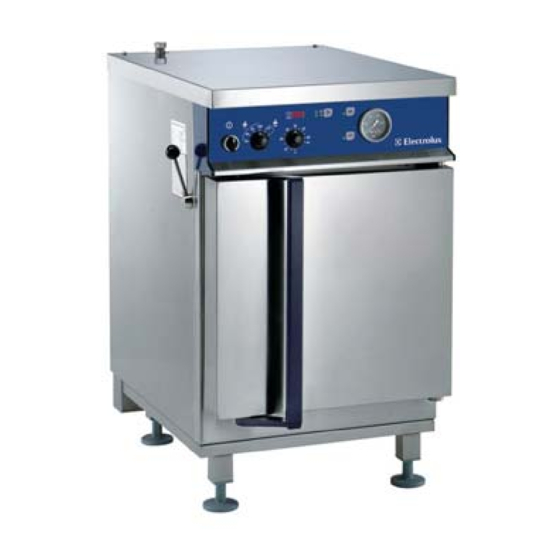
- Page 22 Operating, Installation and Safety Instructions GB/6.95 74.0528.04 (10) PRESSURE STEAMER VARIO STEAM S 33 E...
-
Page 23: Table Of Contents
Operating and installation instructions VARIO STEAM E CONTENTS page OPERATING INSTRUCTIONS..................2 For your safety ....................3 Description .......................3 Operation......................4 Operating the door ................4 Installation of the built-in parts...............5 Controls....................5 Putting into operation ................6 Cooking ....................6 Changing the program ................7 Standby ....................7 Shutting down ..................7 Long period out of operation ..............7 Heating and cooling times ................8... -
Page 24: Operating Instructions
Operating and installation instructions VARIO STEAM E OPERATING INSTRUCTIONS 1. FOR YOUR SAFETY General Door - The installation, adjustment and initial operation of the - The door should be closed during all cooking programs. appliance must be carried out by an authorised - Care should be taken to ensure that the door is correctly serviceman. -
Page 25: Operation
Operating and installation instructions VARIO STEAM E The appliance has three support grids and can be Depending on the type of food being cooked, perforated or equipped with Gastro-Norm trays of the size GN 1/1 in solid trays are used. The former are most frequently used various versions: for steaming. -
Page 26: Installation Of The Built-In Parts
Operating and installation instructions VARIO STEAM E 3.2. INSTALLATION OF THE BUILT-IN PARTS Water tray The clean, empty water tray (11) is installed in the upper part of the cooking compartment. The suspension frames (12) must not be mounted as yet. The tray has three suspension holes (13). -
Page 27: Putting Into Operation
Operating and installation instructions VARIO STEAM E 3.4. PUTTING INTO OPERATION / PREHEATING Before the appliance is put into operation for the first time - Close the door of the appliance. after long shut-down period, cooking - Press the mains switch (1), the lamp lights. This supplies compartment, door, water bath (11) and suspension power to the appliance. -
Page 28: Changing The Program
Operating and installation instructions VARIO STEAM E Pressure steam cooking Pressureless steam cooking Continuous operation Press the Start button (6) (film Press the Start button (6) (film key). The Press the Start button (6) (film key). key). automatic cooking automatic cooking program then begins. The automatic cooking program then program then begins. -
Page 29: Heating And Cooling Times
Operating and installation instructions VARIO STEAM E 4. HEATING AND COOLING TIMES Summarized below are the heating and cooling times for the empty appliance: Preheating the water bath 4 min. From the start to the time the set temperature or pressure is reached 100°C/pressureless 3 min. - Page 30 Operating and installation instructions VARIO STEAM E APPROXIMATE VALUES FOR PRESSURE LEVEL, COOKING TIME AND COOLING Cooking time Cooking time Cooking time Cooling always quickly Food to be cooked (min) (min) pressure (min) pressure (except slowly) pressureless 0.5 bar 1 bar Vegetables Artichokes, whole 20 - 25...
-
Page 31: Cleaning
Operating and installation instructions VARIO STEAM E 6. CLEANING The appliance should be cooled down before cleaning. The drain filter in the base of the cooking compartment The surfaces of the cooking compartment and all other must be cleaned either from outside or, if it is heavily parts are made of stainless chromium nickel steel. - Page 32 Operating and installation instructions VARIO STEAM E especially after cooking potatoes, noodles, rice etc. in salt acid. Treatment with 10% nitric acid is necessary if this water. Dried-on cooking water residues form high proves ineffectual. Due to the associated hazards, this concentration salt solutions which can cause point type of cleaning is only to be carried out by suitably trained corrosion.
-
Page 33: Installation Instruction
Operating and installation instructions VARIO STEAM E INSTALLATION INSTRUCTION both the loading and unloading of trucks as well as to 10. GENERAL REMARKS handling operations on the installation site. Responsibility For handling by a crane, the unpacked ranges do not have The setting up, adjustment and initial commissioning of any specific lifting points to which they can be attached. -
Page 34: Setting Up / Positioning
Operating and installation instructions VARIO STEAM E DIMENSIONAL DRAWING and INSTALLATIONS 13. SETTING UP / POSITIONING The appliance must be installed in an appropriate place and according to the valid installation plans. The appliance must be positioned horizontally on a suitable table by adjusting the screw feet (outer foot part FA, inner foot part FI). -
Page 35: Installations
Operating and installation instructions VARIO STEAM E 14. INSTALLATIONS Please refer to chapter 10 for implementation and responsibility. 14.1. ELECTRICAL CONNECTION Check and ensure that the mains voltage matches the voltage given on the specification plate. N.B.: - The electrical connections must satisfy local house installation regulations. -
Page 36: Waste Water Connection
Operating and installation instructions VARIO STEAM E 14.3. WASTE WATER CONNECTION The appliance has a built-in waste pipe (AW). This pipe is located on the back side of the appliance on the bottom of the drain ventilation pipe (AE). The outer diameter of the pipe (AW) is 25 mm. - Page 37 Service Manual GB/03.01 74.0532.04 (2) PRESSURE STEAMER VARIO STEAM S 33 E...
- Page 38 Service Manual Pressure Steamer CONTENTS Page Validity ............................3 Safety measures........................3 Maintenance interval ......................... 3 Construction / functions ......................4 Functional diagram ........................4 Technical data ........................... 4 Electric diagram......................... 5 Maintenance check list ......................7 Faults............................8 Access to inside......................... 8 Functional components ......................
-
Page 39: Validity
Service Manual Pressure Steamer VALIDITY This document refers to the following types with the above-mentioned functional components: VARIO Steam S-33E, electrically heated steam-o-mat, electrically heated • Pressure appliances of this design and operating mode SAFETY MEASURES do not require special acceptance tests. They are •... -
Page 40: Construction / Functions
Service Manual Pressure Steamer 1. CONSTRUCTION / FUNCTIONS Direct contact with steam is the method used to heat the cooking process to be operated automatically. The food. The steam is generated in the food compartment by programmed settings follow automatically i.e. pressure an electrical heater submerged in a water-filled container. -
Page 41: Electric Diagram
Service Manual Pressure Steamer 3. ELECTRIC DIAGRAM The precise specifications of the individual electric components are given in the corresponding parts list. These must be used in conjunction with the electric diagram valid for the appliance. Power board F1/F2 Terminal with fuse Drain valve cooking Control board K1/K2... - Page 42 Service Manual Pressure Steamer HACCP connection HACCP control switch (On/Off) HACCP control board Temperature sensor for monitoring...
-
Page 43: Maintenance Check List
Service Manual Pressure Steamer 4. MAINTENANCE CHECK LIST Check Fault ⇒ Remedy Connections for protective conductors Connections for equipotentiality Check that all electric connections and contacts to terminals, coils, If contacts are loose ⇒ tighten contacts. switches and junctions are tight. Check contactors and relays (K). -
Page 44: Faults
Service Manual Pressure Steamer 5. FAULTS Disturbance/Fault Possible causes Steam escapes from the door Defective door sealing Displaced door sealing Large steam clouds escape from the drain pipe Soiled drain valve (AV) Soiled or defective steam trap (KO) Soiled or defective ventilation valve (EG) Soiled or defective valve (KA) for cooling the drain Water in the cooking compartment Blocked water drain... -
Page 45: Functional Components
Service Manual Pressure Steamer FUNCTIONAL COMPONENTS SE1. OPERATING FOIL REPLACE Removal Operating foils (FO) are bonded to the sheetmetal surfaces (cover plates) with self-adhesive coatings. They are removed with a spatula, a screwdriver or a knife. Cleaning The surfaces to which the foil is to be applied must be clean and dry, i.e. free from dust, grease, rust, paint, etc. Suitable for cleaning: toluol or 3M article S-152 stick remover. - Page 46 Service Manual Pressure Steamer Water level control in the container and preheating to 80°C Short description Step Function Mode Control Activity Water supply, → Main switch S1 “ON” “Filling” water valve Y2 Water level in the container at safety 1/3 heating (5 kW), →...
-
Page 47: Pressureless Cooking
Service Manual Pressure Steamer Pressureless cooking 70 – 100°C This operating phase follows phase 1. Main switch S1 and door switch S2 are on. Door is closed. Short description Step Function Mode Control Activity 1/3 heating (5 kW), → Press start button “ON”... - Page 48 Service Manual Pressure Steamer Cooking with pressure 0,5 and 1 bar This operating phase follows phase 1. Main switch S1 and door switch S2 are on. Door is closed. Short description Step Function Mode Control Activity none, because S1 → Press start button “ON”...
- Page 49 Service Manual Pressure Steamer Emptying and rinsing the water container This operating phase follows phase 2 or phase 3. The process can be carried out several times in sequence. Main switch S1 is on. Short description Step Function Mode Control Activity Press for Button for emptying the container ET...
-
Page 50: Control Unit With Front Panel
Service Manual Pressure Steamer CONTROL UNIT WITH FRONT PANEL Main switch Interference filter Selector switch for cooking temperature Operating and control board Power board Rotary knob cooking time Thermal insulation Ribbon cable Pressure gauge cooking compartment Front panel Operating foil Electrode for max. - Page 51 Service Manual Pressure Steamer Microprocessor (MP) versions of electrically heated appliances Code/ Date of Remarks colored mark introduction Standard program; This microprocessor cannot appliances with thermostatic used for appliances with serial STEAM1 / yellow 15.05.86 ventilation valve (EG) numbers higher than 81600480.
-
Page 52: Power Board
Service Manual Pressure Steamer POWER BOARD (LP) The pcb cannot be repaired, i.e. it is replaced if it becomes defective. Removal Remove the cover in accordance with §5. Take the ribbon cable (FL) from the power board. Take the pcb off the 6 plastic anchors (VA). - Page 53 Other parts and adjustments of the buzzer see version of 26.11.91. The marking of the new board is: Electrolux CH 6210 Sursee HE- 1000.074 07.2004 Rev. 02 Starting from the 21. Week 2004 with the introduction of a...
-
Page 54: Main Switch
Service Manual Pressure Steamer MAIN SWITCH (S1) New design from 07/97 The control switch is push-button operated: “ON“ when the button is pushed in and the lamp lights up; “OFF” when the button jumps out after being pressed again. To replace the lamp or the switch: Remove the cover in accordance with §5. -
Page 55: Rotary Knob
Service Manual Pressure Steamer ROTARY KNOB TERMINALS (X) Rotary knobs are fitted at the selection switch for cooking Removal and installation temperature and pressure as well as at the switch for terminal strip located above the cooking setting the cooking time. compartment and is accessible from above after the cover Removal has been removed. -
Page 56: Se3. Heating
Service Manual Pressure Steamer SE3. HEATING (HE) The 3 electrical heating elements are fitted directly to the upper side of the cooking compartment (DB). Installation Testing Make sure that the two seals (DI) are new and that the Measurement of the electrical resistances of the individual washer (US) is fitted. -
Page 57: Steam Trap
Service Manual Pressure Steamer STEAM TRAP (KO) The thermic steam trap is located in the drain pipe under the cooking compartment. It functions automatically according to the temperature of the condensate and the steam. It opens when liquid condensate flows to the trap and closes when hot steam attempts to pass through the trap. -
Page 58: Drain Valve
Service Manual Pressure Steamer DRAIN VALVE (AV) (Y1) The solenoid valve is operated electrically by the control system and carries no current when open. The drain valve is only closed when cooking under pressure, i.e. closed. The valve is located in the drain pipe under the cooking compartment. -
Page 59: Water Supply Valves
Service Manual Pressure Steamer WATER SUPPLY VALVES (WV) (Y2 – Y5) The double solenoid valves are operated electrically by and pull the water hoses off the valves. Unscrew the union the control system and carry no current when closed. They nut with which the valve body is attached to the water handle different functions: filling the container, emptying supply. -
Page 60: Emptying The Container
Service Manual Pressure Steamer EMPTYING THE CONTAINER The water container (BA) is emptied by feeding (IK) water via the valve (Y3) and the pipe (EW). The pipe (ZW) remains closed. As soon as the pipe that goes downwards is full of water, the flow of water is stopped whereupon the water will exit the container by itself due to the suction effect of the vacuum in the downward pointing pipe. -
Page 61: Se5. Pressure Test Cooking Compartment
Service Manual Pressure Steamer SE5. PRESSURE TEST OF THE COOKING COMPARTMENT (DB) Whilst a pressure test carried out at fixed intervals is not compulsory, the operator should have a pressure test carried out periodically in the interest of troublefree operation and safety. The pressure test is done with cold water taken from the water main. -
Page 62: Se7. Door Sealing
Service Manual Pressure Steamer SE6. DOOR (TR) DOOR REPLACEMENT Removal - Remove the cover and both sidewalls in accordance with §5. Remove the right sidewall in the same way as the left sidewall. - Remove the front cladding of the door by undoing 2 screws each on the upper and lower narrow side. -
Page 63: Se8. Door Lock
Service Manual Pressure Steamer SE8. DOOR LOCK After replacing parts of the lock, all the elements must be reset, secured and sealed (lead seal). The numbers in following descriptions correspond to the position numbers in the spare parts list. REMOVAL/INSTALLATION of LOCK PARTS PANELS (113) Removal Remove the cover (60), left sidewall... - Page 64 Service Manual Pressure Steamer DOOR HANDLE (112) Removal Unscrew screws (135, 136) totally. Take out the handle (112) from above. Remove the screw (119) to release the lower lever (111). The bearing bushes (84) are a press-fit in the door and can be removed. LOCK SPINDLE (115) Removal Slacken screws (130) on the clamping ring (114).
- Page 65 Service Manual Pressure Steamer LOCK HOOK PARTS Assembling Fit fork (109) with roller (107), spring pin (108) and springs (110) together. Place 4 washers (128) on the fork (109) and fix them with the nuts (102, 103) provisional on the lock hook (101). LOCK HOOK Installation Attach the lock hook (101) with springs (110) in the...
- Page 66 Service Manual Pressure Steamer HANDLE (112) Installation Insert handle (112) from above. Dab screws (135, 136) with Loctite 243 and screw them in. CATCH SCREW (117) Installation Open door lock, turn handle as far as stop (BB) and hold. Dab catch screw (117) with Loctite 243 and screw it in.
-
Page 67: Adjustments To The Door Lock
Service Manual Pressure Steamer ADJUSTMENTS to the DOOR LOCK LOCK HOOK (101) In the open position of the door lock, the distance between lock hook (101) and wedge (121) must be in the range of 0.5 – 3 mm. Adjusting Open the door lock. - Page 68 Service Manual Pressure Steamer POSITION OF PIN (104) The distance between pin (104) and end of the wedge (100) must be 22 +0,5/-0 mm with door lock closed. Readjustment If the gap is less than 22 mm, readjustment is possible by adjusting (filing down) the stop (D).
- Page 69 Service Manual Pressure Steamer CLAMPING RING (114) MOUNTING This operation is only carried out when: Reinstalling at the factory The lock spindle (115) has to be replaced Converting from the previous to the new lock system Screw drilling jig (142) in clamping ring (114). Drill a hole ∅...
- Page 70 Service Manual Pressure Steamer DOOR SAFETY SWITCH (122) The functioning of the electrical safety switch must be checked periodically. The end position of the lock is monitored by this electrical switch (122). If the hook is not in its closed end position, the switch is open and will prevent the heating in the cooking compartment from being operated...
-
Page 71: Door Catch With Pressure Release
Service Manual Pressure Steamer DOOR CATCH WITH PRESSURE RELEASE (Safety measure) The lever (HV) on the front of the left- hand side of the appliance is used to lock the hook (101) via a pin when the door is closed and to operate the tap (HH). -
Page 72: Drain Separator
Service Manual Pressure Steamer DRAIN SEPARATOR (AE) The drain separator (AE), which consists of a piece of square tube, is fitted to the back of the appliance where it fulfills the following functions: - Separation by the wall (TW) of water and steam after exiting the appliance at outlets AA and LD: The water exits through the spigot (AL). -
Page 73: Function Check
Service Manual Pressure Steamer FUNCTION CHECK Following servicing work on the door lock, the appliance must be given a full check of all operating levels (pressure-free, 0.5 bar, 1 bar); i.e. build up pressure, release pressure, operate the door and the lock several times. SERVICE AND MAINTENANCE REPORT FOR THE PRESSURE LOCK All servicing must be carried out as described in the manufacturer’s manual.
Need help?
Do you have a question about the VARIO STEAM S33-E and is the answer not in the manual?
Questions and answers