Table of Contents
Advertisement
Quick Links
Advertisement
Table of Contents

Related Manuals for Ulvac PMB-040C


Summary of Contents for Ulvac PMB-040C
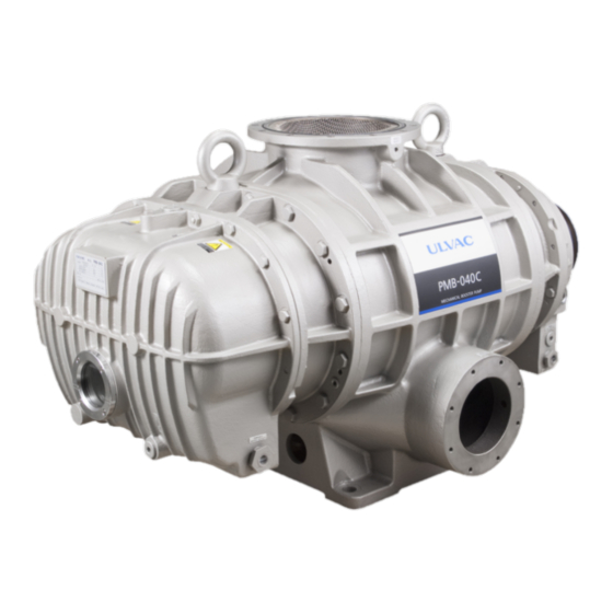
- Page 1 YK10-0015-DI-002-03 INSTRUCTION MANUAL MECHANICAL BOOSTER PUMP PMB-040C PMB-060C Before using this product, be sure to read this operation manual. Keep this manual with care to use at any time. ULVAC, Inc. Components Division http://www.ulvac.co.jp/...
- Page 3 The performance and safety of the product might not be ensured if any of the devices put together did not conform to same regulations or the product itself was modified. ULVAC shall be not liable to guarantee performance and safety in such cases above. Any modification of the product by the user is out of the scope of guarantee by us and not be guaranteed in any manner.
-
Page 4: Safety Symbol Marks
● It is prohibited to use this instruction manual except for IMPORTANT explanation when using the PMB-040C and PMB-060C, and other purpose Components Division of ULVAC, Inc. agreed. ● It is prohibited to hand over and disclose this instruction manual to third parties without agreement by Components Division of ULVAC, Inc. -
Page 5: Safety Precautions
YK10-0015-DI-002-03 ● Training for the electrical safety is required as there is a risk of electrical shock. ● Check and ensure that the pump is sufficiently cooled down as this section keeps high temperature after having stopped the pump. 0.3 Safety Precautions Descriptions are given as the method to keep away from danger and actions that must be restricted on the use of the product. - Page 6 YK10-0015-DI-002-03 ● We would be obliged to refrain from handling and/or executing maintenance of the product if the detail of used hazardous substance was not disclosed or the product has exhausted such substance that the detoxification process is hardly conducted. WARNING ●...
- Page 7 ● You have a risk of giving damage to your back as the load larger than safety standard shall be required to transfer the product. PMB-040C:970kg (Without Motor) PMB-060C:1100kg (Without Motor) Be sure to use the loading machinery (such as mobile crane) to lift up the Pump or load it on the pallet and fix it with Jack and run the Pallet truck for its transfer.
- Page 8 YK10-0015-DI-002-03 Inlet / outlet port piping <Mounting> ● Check and ensure that any of hazardous energy is blocked before starting the operation. WARNING Coolant piping <Mounting> ● Check and ensure that any of hazardous energy is blocked before starting the operation. WARNING Power Supply wiring <Mounting>...
- Page 9 YK10-0015-DI-002-03 Operation ● Do not run the pump on blocking the exhaust outlet or putting any device that might hamper gas passage onto the outlet. There is a risk that the pressure inside the vacuum pump rises up to cause break or oil leak of the casing or oil level gauge resulting in overload of the motor.
- Page 10 YK10-0015-DI-002-03 ● Ensure to flow the cooling water during operation. Required Cooling water shall be; Cooling water volume : 10 L/min or more Cooling water temperature : 5°C ~ 30°C ● It is recommended to use water with a low number of impurities (e.g. industrial water;...
- Page 11 ● You have a risk of giving damage to your back as the load larger than safety standard shall be required to transfer the product. PMB-040C:970kg (Without Motor) PMB-060C:1100kg (Without Motor) ● Be sure to use the loading machinery (such as mobile crane) to lift up the Pump or load it on the pallet and fix it with Jack and run the Pallet truck for its transfer.
-
Page 12: Types And Descriptions Of Warning Labels Displayed On This Machine And Displayed Positions
YK10-0015-DI-002-03 0.4 Types and Descriptions of Warning Labels Displayed on This Machine and Displayed Positions Warning labels are attached on the warning locations in this system. Be sure to check them before starting operation of the Pump. Before use, read through the instruction manual and fully understand its contents. - Page 13 YK10-0015-DI-002-03 This indicates the rotation direction of the belt. In this machine, the motor pulley becomes different when moving at 60Hz and when moving at 50Hz. Confirm the description of frequency on the label. Fig. 1 Warning Label...
-
Page 14: Acceptance And Storage Of The Pump
YK10-0015-DI-002-03 0.5 Acceptance and Storage of the Pump 0.5.1 Unpacking/Acceptance of the Pump ● This product is packed with the wooden frame. Please ask the special agency for dismantling it. Advise the dismantling agent to wear leather gloves and use appropriate tools such as pinch bar as they have a risk of cutting the hand by nail or chip. -
Page 15: Transfer
● You have a risk of giving damage to your back as the load larger than safety standard shall be required to transfer the product. PMB-040C:970kg (Without Motor) PMB-060C:1100kg (Without Motor) Be sure to use the loading machinery (such as mobile crane) to lift up the Pump or load it on the pallet and fix it with Jack and run the Pallet truck for its transfer. -
Page 16: Ambient Condition For Storage, Install And Operation
YK10-0015-DI-002-03 0.5.3 Ambient Condition for Storage, Install and Operation As precise clearances are provided with this machine, be sure to fulfill the following for its storage, install and operation; (1) Ambient temperature and humidity for : -10°C to 60°C, less than 95%RH storage (No freeze/condensation) (2) Ambient temperature and humidity for... -
Page 17: Protective Device
● In order to avoid any unnecessary instantaneous action, it is necessary to take another look at the selection of MCCB, ELCB, and THR. For the motor protection (thermal) of PMB-040C and -060C, a time-lagged type is recommended. CAUTION Example: Fuji Electric FA Components & Systems Co., Ltd. -
Page 18: Table Of Contents
YK10-0015-DI-002-03 Table of Contents 0. Before Using This Product ........................i 0.1 Safety Symbol Marks ......................... ii 0.2 Meanings of Safety Symbol Marks ....................ii 0.3 Safety Precautions..........................iii 0.4 Types and Descriptions of Warning Labels Displayed on This Machine and Displayed Positions ..x 0.5 Acceptance and Storage of the Pump ..................... - Page 19 8.6 Others ............................. 44 9. Main Displacement Parts ........................45 APPENDIX 1 TECHNICAL NOTE ......................46 APPENDIX 1.1 Designing Pumping System ..................46 APPENDIX 1.2 Automatic Operation ....................47 Request Form for Repair/Inspection of ULVAC Components /Certificate of Contamination SERVICE CENTER Contents-2...
- Page 20 Fig. 2 Pumping mechanism of mechanical booster pump ................. 5 Fig. 3 Dimensional drawing PMB-040C ..................... 7 Fig. 4 Dimensional drawing PMB-060C ..................... 8 Fig. 5 Foundation Drawing Model PMB-040C ................... 9 Fig. 6 Foundation Drawing Model PMB-060C ..................10 Fig. 7 Pumping speed curves ........................11 Fig.
-
Page 21: For Your Safety Use
● There is a risk that the Pump might Getting injured on drop or lay down when attempted transferring the pump. unreasonable operation or machinery setup was not sufficient. You are strictly restricted from entering beneath the Pump. Pump weight (without motor) PMB-040C:970 kg PMB-060C:1,100 kg... -
Page 22: Warning Electric Shock
YK10-0015-DI-002-03 1.1.3 Warning Electric shock Factors Avoidance methods and measures ● Be sure to cut the electricity to do electrical connection. ● Be sure to establish a ground. ● Be sure to close the cover of the terminal box of the motor before Getting electrical shock on operating the pump and do not open the touching the... -
Page 23: Caution High Temperature
YK10-0015-DI-002-03 1.1.5 Caution High temperature Factors Avoidance methods and measures ● The Pump gets high temperature during operation. ● As the surface temperature is high, you have a risk of getting burnt by accidentally touching it with the hand or the like. -
Page 24: Chemical Material Safety Data Sheet(Sds
YK10-0015-DI-002-03 1.2 Chemical Material Safety Data Sheet(SDS) ● Chemical material used for this Pump; ULVOIL R-72 (Mineral oil) ● The Chemical Material Safety Data Sheet introduces the chemical material potential to use or touch on operating this machine. IMPORTANT ● Please contact our Sales division if you are in need. Read it with attention to acknowledge the toxic characteristics described on the SDS. -
Page 25: Pump Outline
YK10-0015-DI-002-03 2. Pump Outline 2.1 Total configuration The Mechanical booster pump is used combined with the backing pump to enhance the exhaust speed around the pressure range 8.0×10 ~ 6.7×10 Pa where the backing pump exhaust speed is likely to lower. The mechanical booster pump includes two rotors having a cocoon-shaped cross section and a casing that encloses them. -
Page 26: Performance Specifications
YK10-0015-DI-002-03 2.2 Performance Specifications Table. 2 Specifications Specifications Model PMB-040C PMB-060C Pumping Speed m 3800 6200 Maximum intake pressure Pa *1.6 8.0 × 10 Ultimate Pressure Pa *2.6 6.7 × 10 6.7 × 10 Backing Pump PKS-070 1 PKS-070 2... -
Page 27: Dimensional Drawing
YK10-0015-DI-002-03 2.3 Dimensional drawing Fig. 3 Dimensional drawing PMB-040C... - Page 28 YK10-0015-DI-002-03 Fig. 4 Dimensional drawing PMB-060C...
- Page 29 YK10-0015-DI-002-03 Fig. 5 Foundation Drawing Model PMB-040C...
- Page 30 YK10-0015-DI-002-03 Fig. 6 Foundation Drawing Model PMB-060C...
-
Page 31: Pump Performance
YK10-0015-DI-002-03 2.4 Pump Performance 2.4.1 Ultimate pressure The ultimate pressure of the mechanical booster pump depends on that of the backing pump. Take special care when using the backing pump other than the standard combination. In the event of an abnormal ultimate pressure, it is also necessary to check the ultimate pressure of the backing pump alone. -
Page 32: Power Requirements
YK10-0015-DI-002-03 2.4.3 Power Requirements The power requirement of the mechanical booster pump varies with the intake pressure and the performance of the backing pump. With the standard backing pump, the motor is overloaded at an intake pressure of more than the maximum intake pressure (Refer to the “Table. -
Page 33: Mounting
YK10-0015-DI-002-03 3. Mounting ● You are requested to install and operate the product in compliance with the laws and regulations relating to the safety, e.g. Fire Defense Law, Electric wiring regulation and so on in the country and region you use the product. Consequently you shall be requested to attend general safety lectures officially effective in the area, such as electrical safety, Cargo handling safety and so on. -
Page 34: Inlet Port Piping/ Outlet Port Piping
JIS B 2290:1998 Vacuum technology-Flange dimensions; Attachment book (Reference) Flange dimensions for maintenance (1) Use the JIS vacuum flange (VF250) to connect the pipe to the inlet of PMB-040C. Use the JIS vacuum flange (VF300) to connect the pipe to the inlet of PMB-060C. - Page 35 YK10-0015-DI-002-03 ● If the pipe connected to the outlet had a small diameter or attached foreign substance inside, it might raise the pressure inside the pipe and impair the pump operation. A caution shall be required. CAUTION ● Take a countermeasure to avoid any direct load to the Pump flange such like to choose the pipe with bellows to connect with the inlet and outlet.
-
Page 36: Cooling Water Piping
YK10-0015-DI-002-03 3.4 Cooling Water Piping Install the piping in reference to Figs. 3 and 4. Do not confuse between the cooling water inlet and outlet. ● Be sure to feed cooling water by the amount or more specified in "Table 2: Specifications." If the amount of water becomes lower than the specified value especially during the operation at a high suction pressure, the pump temperature may increase and it damages the pump. - Page 37 YK10-0015-DI-002-03 ● The machine is designed not to cause any leakage under restricted condition and demonstrated by the Leak test. However, it still has a risk of leaking under any abnormal condition other than specified, for example abnormal water pressure rise. In such a case, the leakage shall remain unstopped unless the supply from the system stops.
-
Page 38: Electrical Connection
YK10-0015-DI-002-03 3.5 Electrical Connection ● Be sure to attach a belt cover when making electrical connections. ● The direction of rotation is indicated by an arrow on the belt cover. Make connections to the motor so that it rotates in that direction. (See "Figure 1: Labeling Position.") ●... - Page 39 ● In order to avoid any unnecessary instantaneous action, it is necessary to take another look at the selection of MCCB, ELCB, and THR. For the motor protection (thermal) of PMB-040C and -060C, a time-lagged type is recommended. CAUTION Example: Fuji Electric FA Components & Systems Co., Ltd.
- Page 40 58.8 50Hz 55.6 200V - 55.6 200V 60Hz class 52.0 220V - 52.0 motor 60Hz 50.6 230V - 50.6 60Hz PMB-040C 29.4 400V - 29.4 50Hz 27.8 400V - 27.8 400V 60Hz class 26.0 440V - 26.0 motor 60Hz 25.3 460V - 25.3...
- Page 41 YK10-0015-DI-002-03 ● Turn OFF the Power Supply to do the electrical connection. Never try to work on it on keeping the electricity turned ON. ● A correct wiring work must observe the law and the rule that relates safely. A wrong wiring work might start a fire. ●...
-
Page 42: Lubrication
YK10-0015-DI-002-03 3.6 Lubrication 3.6.1 Lubrication to the lubrication chamber. Supply the lubrication oil by specified volume through the oiling port on the Gear cover and the pulley cover (Refer to Fig.3, Fig.4 ). It takes approximately one minute that the lubrication oil fully spreads out. Check the oil volume by the Oil level gauge after the lubrication got stabled and add the oil if it was under the specified level as far as the oil gets stabled on the upper limit level. - Page 43 SDS. CAUTION ● Ensure to use the vacuum pump oil designated by ULVAC. Operation using oil other than designated shall be out of our scope of guarantee as it might impair the pump performance and shorten the life cycle.
-
Page 44: Lubrication To The Mechanical Seal
YK10-0015-DI-002-03 ● Be sure to pour oil. ● If the oil level becomes lower than the lower limit during the operation, the bearings, gears, shaft seals, etc. are damaged, causing leakage, abnormal noise, overloaded motors, or a CAUTION shutdown. 3.6.2 Lubrication to the mechanical seal There is a mechanical seal inside the cover on the pulley side. -
Page 45: Oil Pot
YK10-0015-DI-002-03 3.7 Oil Pot The mechanical seals structurally cause a slight oil leakage under normal conditions. Approx. one month after the startup is the running-in period of the sealing surfaces of the mechanical seals and the amount of leakage may increase temporarily. In addition, during the running-in period the mechanical seals may cause a metallic noise of high frequency. -
Page 46: Check And Replace V-Belt
YK10-0015-DI-002-03 3.8 Check and Replace V-belt ● When performing the work of the inspection/replacement of the belt, perform the work after turning off the power switch without fail. ● The measures such as lockout/tag out should be executed not so as to WARNING turn the power switch by mistakes during working. - Page 47 YK10-0015-DI-002-03 Table. 5 Flexible volume, deflection load of the belt When tightening When re-tightening the new belt Reference value of Operating Range of flexible load Range of deflection load Model flexible volume frequency N/1 pce N/1 pce 50Hz PMB-040C 16.3 60Hz 57.8~63.7 50Hz...
-
Page 48: Operation
YK10-0015-DI-002-03 4. Operation 4.1 Precautions for Operation ● Never run the vacuum pump on blocking up the exhaust outlet, putting any device that hampers the gas passage. There is a risk that pressure in the pump rises, and the main body of the pump and the oil level gauge might explode, or the motor become an overload. -
Page 49: Startup
YK10-0015-DI-002-03 ● When using the automatic vacuum breaker (Time lag electromagnetic leak valve which introduces the air in the pump by the valve opening in 3 ~ 5 sec. after stopping the motor for the pump drive), do connection so that it gangs with the motor. CAUTION 4.2 Startup 4.2.1 Test run... -
Page 50: Exhaust Start
YK10-0015-DI-002-03 4.2.2 Exhaust start (1) Flow the Cooling water. (2) Close the main valve of the Mechanical booster pump and start running the backing pump to exhaust inside pipes. (3) Open the mechanical pump on the suction side of the mechanical booster pump, and exhaust inside the vacuum vessel. - Page 51 YK10-0015-DI-002-03 ●Discharge the water in the Pump unit and Cooling water piping in case where the environment temperature comes down below 5℃ under the state that the operation is stopped (Supply the compressed air of 0.3MPaG (gauge pressure) through the cooling water inlet without closing the outlet.).
-
Page 52: Maintenance And Check
YK10-0015-DI-002-03 5. Maintenance and Check 5.1 Maintenance Conduct the maintenance regularly in appropriate check interval. Maintenance period shall differ depending on the operation purpose. Set the interval once a day at first. Once a week from next week if you had no problem, then conduct once a month for example. We recommend you, however, to conduct visual checks and check on the utility every day to see the system condition. -
Page 53: Pump Oil Level Check
YK10-0015-DI-002-03 5.2.1 Pump oil level check Set the oil level so that it is within the appropriate range of the oil level gauge during the operation. 5.2.2 Pump oil check The vacuum pump oil is not only contaminated by suction gas but also gradually deteriorated by a temperature rise during the pump operation. - Page 54 YK10-0015-DI-002-03 ● Ensure to use the vacuum pump oil designated by ULVAC. Operation using oil other than designated shall be out of our scope of guarantee as it might impair the pump performance and shorten the life cycle. CAUTION ●When newly filling the mechanical booster pump with lubrication oil...
-
Page 55: Oil Leakage Check
YK10-0015-DI-002-03 5.2.4 Oil leakage check In the event of an oil leakage from the shaft-seal part or the pump body, it need to be repaired. The O-rings used in this machine are described at the end of this document. Contact the nearest service center. -
Page 56: Checking Inside Of Casing
YK10-0015-DI-002-03 5.2.9 Checking inside of casing Stop the mechanical booster pump once every three months, remove the piping of the air intake, and check the inside. Check that there is no deposit inside the casing (the rotor and casing surfaces). Especially when organic gas etc. is exhausted, substances in the gas condense and attached to the rotor surface, reducing its clearance and then making the rotation impossible. -
Page 57: Trouble Shooting
YK10-0015-DI-002-03 5.5 Trouble shooting Table. 6 Troubleshooting Trouble Causes Processing Method Reference Are all three phases of power supply Abnormal phase voltage. normal? Check the power supply. Motor connection is wrong. Check the connection. Safety circuit such as the Make the Safety circuit conform to NFB and Electromagnetic the Motor specification. - Page 58 Put filters into the front stage of the pump. New oil pump was just Perform no-load operation for a entered. while. Conduct the overhaul of the Pump Not using the ULVAC genuine and replace the oil with the ULVAC oil. oil.
- Page 59 YK10-0015-DI-002-03 Trouble Causes Processing Method Reference Motor rotation direction is Do the connection again to correct reverse. the rotation direction. Cooling water does not flow. Keep flowing the cooling water by (Specified volume is not the specified volume. flowing.) Oil is not filled. Overhaul Oil is under the lower (Replacement of the pump part)
- Page 60 YK10-0015-DI-002-03 Trouble Causes Processing Method Reference Install a cooling device such as the Suction gas is hot. - Gas cooler on the suction side. Oil is stained. Replace to new oil. temperature Cooling water does not flow. Keep flowing the cooling water by on the pump (Specified volume is not the specified volume.
-
Page 61: Removal / Transport
●You have a risk of giving damage to your back as the load larger than safety standard shall be required to transfer the product. PMB-040C:970kg(Without Motor) PMB-060C:1100kg(Without Motor) Be sure to use the loading machinery (such as mobile crane) to lift up the Pump or load it on the pallet and fix it with Jack and run the Pallet truck for its transfer. -
Page 62: Disposal
YK10-0015-DI-002-03 7. Disposal Make sure to keep in compliance with the laws and regulations established by the local governments to dispose the Vacuum pump. You should ask the dedicated disposal agency for the disposal particularly if the Pump has exhausted any toxic gas. Note that you are requested to bear the cost and charges relating to the disposal. -
Page 63: Warranty Clauses
8.4 Response Procedure (1) For domestic transaction: We send you a substitute or repair the product you send back to us or the nearest ULVAC TECHNO's office. If you need support on site, consult the nearest sales office or agency separately. -
Page 64: Disclaimer
(1) In case, special agreement or memorandum for specifications is made individually. (2) Buyer shall inform ULVAC when this product is exported out of Japan. In the meantime, Buyer shall take necessary procedures according to Foreign Exchange and Foreign Trade Law. -
Page 65: Main Displacement Parts
YK10-0015-DI-002-03 9. Main Displacement Parts Table. 7 Main displacement parts list Part name Location PMB-040C PMB-060C Material Bearing (*1) Pulley side SUJ2 Bearing Gear side SUJ2 (*1) Spacer Bearing case 1set 1set Mechanical seal Mechanical seal Lip seal Shaft PTFE... -
Page 66: Appendix 1 Technical Note
YK10-0015-DI-002-03 APPENDIX 1 TECHNICAL NOTE The following is a short note of the knowledge required in using a mechanical booster pump. APPENDIX 1.1 Designing Pumping System The mechanical booster pump cannot be started at the atmospheric pressure and must always be used in combination with a backing pump (Dry pump/Oil rotary pump). -
Page 67: Appendix 1.2 Automatic Operation
YK10-0015-DI-002-03 APPENDIX 1.2 Automatic Operation The mechanical booster pump PMB-040C, PMB-060C has a certain operating pressure range. When starting it, therefore, it is necessary to monitor the vacuum gauge. In automatic operation, it is necessary to install a vacuum switch for pressure detection. When the pressure on the intake side becomes lower than the maximum intake pressure, the vacuum switch is actuated to start the mechanical booster pump. - Page 68 ULVAC service center or sales office prior to shipment. Please consult with your closest local ULVAC service center or sales office if our components are used with toxic gases or contaminated with reactive products or substances produced by reaction.
-
Page 69: Service Center
. co . jp 東京都港区港南2-3-13 TEL:03-5769-5511 アルバック販売株式会社 大阪支店 〒532-0003 大阪府大阪市淀川区宮原3-3-31 TEL:06-6397-2286 ULVAC ,Inc. http://www.ulvac.co.jp/en/ Service Centers http://www.ulvac.co.jp/en/support/service-center/ Sales Offices http://www.ulvac.co.jp/en/support/sales-offices/ ULVAC, Inc. Components Division 2500 Hagisono, Chigasaki, Kanagawa, 253-8543, Japan TEL: +81-467-89-2261 ulvac . co . jp / en rev5.1...
Need help?
Do you have a question about the PMB-040C and is the answer not in the manual?
Questions and answers