Table of Contents
Advertisement
Quick Links
No.18400-2-03-13
Instruction Manual
for
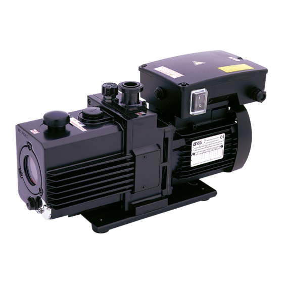
Direct-Drive Oil Sealed Rotary Vacuum Pump
Model
GLD-040
Before using the product, be sure to read this manual.
Keep this manual in a place where it can be referred to at any time
and look after it carefully.
The contents of this instruction manual are subject to change
without prior notice due to improvements in performance and the
functions of the product.
ULVAC KIKO,Inc.
Advertisement
Table of Contents

Related Manuals for Ulvac GLD-040


Summary of Contents for Ulvac GLD-040
- Page 1 Instruction Manual Direct-Drive Oil Sealed Rotary Vacuum Pump Model GLD-040 Before using the product, be sure to read this manual. Keep this manual in a place where it can be referred to at any time and look after it carefully.
- Page 2 2006/42/EC Machinery Directive declare under our sole responsibility that the product, Type of Product : Oil Sealed Rotary Vacuum Pump Model Name : GLD-040,GLD-136A,GLD-137AA, GLD-201A,GLD-202AA,GLD-280A, GLD-136C,GLD-137CC,GLD-201B, GLD-202BB, GLD-280B to which this declaration related is in conformity with the following standards: EN 1012-2:1996+A1:2009 Compressors and vacuum pumps –...
- Page 3 0. Introduction 0.1 Before using the vacuum pump Thank you for purchasing our vacuum pump (hereinafter called “pump”). When you have received the pump, check that the delivered pump is as per your order and that it has not been damaged in transportation, etc.
-
Page 4: Safety Symbols
0.2 Safety symbols In this instruction manual and on warning labels attached to the pump, the following symbols are used so that matters which must be strictly adhered to can be readily understood. These symbols are divided as shown below. Danger When mishandled, there is an imminent danger of the operator suffering a fatal accident or serious injury. -
Page 5: Cautions For Safety
0.3 Cautions for safety Danger This pump is for dry air or the dry nitrogen suck only. Warning Never allow people other than repair engineers to disassemble or repair the pump. Failure to do so may result in ignition or malfunction, leading to injury or electric shock. - Page 6 Caution Never touch the rotating section of the motor, shaft or coupling while the pump is in operation. Failure to do so will result in injury. Caution Never place combustible materials around the motor or pump. There is a risk of fire.
-
Page 7: Acceptance And Storage Of The Pump
0.4 Acceptance and storage of the pump 0.4.1 Acceptance of the pump Although the pump is delivered with great care, check the following after unpacking. ① The delivered pump is in accordance with your request. ② The specified accessories (enough pump oil to use the pump once; optional equipment) have been provided. - Page 8 0.5 Protective device The pump is equipped with a single-phase 100-120 V (50/60 Hz) and 200-240 V (50/60 Hz) motor. This motor has a total of two overload protectors built in: one is of automatic reset type and the other of manual reset type.
-
Page 9: Table Of Contents
Contents 0. Introduction ·························· 01 0.1 Before using the vacuum pump ·························· 01 0.2 Safety symbols ·························· 02 0.3 Cautions for safety ·························· 03 0.4 Acceptance and storage of the pump ·························· 05 0.4.1 Acceptance of the pump ·························· 05 0.4.2 Environmental conditions for storage, installation and operation ··... - Page 10 5. Pump Performance ·························· 18 5.1 Ultimate pressure ·························· 18 5.2 Pumping speed ·························· 18 5.3 Power requirement ·························· 18 6. Maintenance, Inspection and Repair ·························· 20 6.1 Maintenance ·························· 20 6.2 Periodic inspection ·························· 20 6.3 Replacement of the pump oil ··························...
- Page 11 Figures and Tables Fig. 1 Dimensional drawing of GLD-040 oil sealed rotary vacuum pump ·········· 4 Fig. 2 Transportation method of the oil sealed rotary vacuum pump ············ 5 Fig. 3 Lubrication of the oil sealed rotary vacuum pump ······················ 6 Fig.
-
Page 12: Introduction
1. For Safe Operation 1.1 Hazards peculiar to the pump and safety measures Before operating or inspecting the pump, read this section carefully to fully understand potential hazards and prevention methods. The pump is not to be used with toxic of flammable gases. 1.1.1 Danger Leakage of hazardous gases and substances Cause... -
Page 13: Warning Explosion
1.1.3 Warning Explosion Cause Prevention method and measures ⇒ The maximum internal pump pressure is 0.03 MPa (gauge The pressure in the pump increased causing the pump pressure). to explode. Measure the pressure at the outlet side and, if the pressure is 0.03 MPa or more (gauge pressure), remove objects which block the passage of gas from the outlet side. -
Page 14: Outline Of The Pump
This oil sealed rotary vacuum pump is a rotary vane pump (hereinafter called Gaede type pump) in which the pump is directly driven by the motor. Since the pump is small, light, and quite simply constructed, it is easily maintained and repaired. Table 1 Specification GLD-040 Model Unit 50 Hz... -
Page 15: Dimensional Drawing
2.2 Dimensional drawing Fig. 1 Dimensional drawing of GLD-040 oil sealed rotary vacuum pump - 4 -... -
Page 16: Installation
3. Installation 3.1 Installation The pump should be installed on a level surface in a location with minimal dust, dirt and humidity and be arranged with consideration given to ease of installation, removal, inspection and cleaning. Particular attention should be paid to the ambient temperature when building the pump into equipment. -
Page 17: Lubrication
3.2 Lubrication Remove the oil inlet plug from the oil inlet port, and add the pump oil which has been delivered together with the pump or the pump oil specified by us (R-2) up to the range marked with the line on the oil level gauge. -
Page 18: Vacuum Piping
3.3 Vacuum piping (1) Before connecting the pipe to the pump, clean the inner walls of the vacuum chamber, piping and vacuum valve to completely eliminate moisture, fine particles, dust, dirt and rust. Note If fine particles, dust or dirt, etc are evacuated, the pump may malfunction. If moisture is evacuated, not only does the ultimate pressure increase but also the inside of the pump becomes rusty causing the pump to malfunction. -
Page 19: Electric Wiring
3.4 Electric wiring (1) The pump rotates in the clockwise direction as seen from the front of the pump (level gauge side). (2) When wiring, open the terminal box of the motor and connect the wires as shown in Fig. 5. (3) Please select the power supply cord with a suitable plug to the power-supply voltage, and connect wires by using pressure wear terminal (#250) with the insulation coating as shown in Fig 6. -
Page 20: Fig. 5 Electric Wiring Diagram
Note Check with a qualified electrician or serviceman when the grounding instructions are not completely understood, or when in doubt as to whether the product is properly grounded. Do not modify the plug provided; if it does not fit the outlet, have the proper outlet installed by a qualified electrician. Note This pump must be connected to a grounded, metallic, permanent wiring system, or an equipment-grounding terminal or lead on the product. -
Page 21: Fluctuation In The Power Voltage And Frequency
3.5 Fluctuations in the power voltage and frequency Standard: Rotation electricity machine general rules JIS C 4034-1:1999,JEC-2137-2000 To the voltage change and frequency change in Domain A, in main rated values, it operates continuously, and can be used practically convenient, and to the voltage change and frequency change in Domain B, it shall operate with main rated values and shall be used practically convenient. -
Page 22: Operation
4. Operation 4.1 Cautions for operation Warning There is a risk of explosion. Never block the outlet or operate the pump with equipment mounted at the outlet side which blocks the passage of gas. Otherwise, the pump internal pressure increases causing the pump to explode, the oil level gauge to protrude or the motor to be overloaded. -
Page 23: Start Of Operation
4.2 Start of operation To start operation, close leak valve (B), open vacuum valve (A) to the inlet port, and turn on the power switch. Then the pump starts beings to exhaust (see Fig. 4). Caution ① The motor and pump become hot (temperature increase under non-load operation: 15K, temperature increase under high-load operation: 50K) during operation of the pump. -
Page 24: Operation In Cold Climates
4.4 Operation in cold climates When using the pump in winter, in cold climates, or outdoors, it is sometimes difficult to start the pump. This is an overload phenomenon resulting from the increase in the viscosity of the pump oil. To start the pump in such conditions, warm up the pump oil, or turn the pump on and off several times in short intervals. -
Page 25: Automatic Reset Type Thermal Protector
4.6 Autonatic reset type Thermal protector Auto reset thermal protector is incorporated in the motor in order to interrupt the power circuit of the motor and prevent damage to the motor when an over current flows through the motor due to a stop in rotation or overload resulting from the pump malfunctioning during operation. Table 2 Characteristics of the thermal protector Operation temperature 120±5℃... -
Page 26: Fig. 9 Interior Of Terminal Box,Gld-040
Relay Manual reset type thermal protector Figure. 9 Interior of Terminal Box, GLD-040 Time usually At operation Figure. 10 Manual Reset Type Thermal Protector Warning Once the manual reset type thermal protector has functioned, please return the pump to us. Should the motor be started up after resetting the thermal protector, a large current may continue flowing in the auxiliary coil, probably leading to its burnout. -
Page 27: Gas Ballast Valve
4.8 Gas ballast valve The pump is equipped with a gas ballast valve in order to evacuate vapor and condensable gases such as solvent vapor. Evacuated condensable gas that liquefies in the compression and pressurization processes of the pump is mixed with the pump oil and starts circulating through the pump together with the oil. In such a case, the same effect as when oil of a high steam pressure is used is produced, and the ultimate pressure of the pump increases. -
Page 28: Installation Of The Oil Mist Trap (Option)
4.9 Installation of the oil mist trap (Option) An oil mist trap can be installed in order to remove oil mist from the pump. As such an oil mist trap, models OMS-050 and OMT-050A are available. Remove the standard exhaust port from the exhaust port of the pump and install an oil mist trap instead. -
Page 29: Pump Performance
5. Pump Performance 5.1 Ultimate pressure The term “ultimate pressure” as employed in the catalogue and in this manual is defined as “the minimum pressure obtained by the pump without the introduction of gas from the pump inlet (i.e. the non-load condition).” For this pump, measurement is performed using the specified pump oil with only a Pirani vacuum gauge installed at the pump inlet port. -
Page 30: Fig. 11 Pumping Speed Curve
Fig. 11 Pumping speed curve - 19 -... -
Page 31: Maintenance, Inspection And Repair
6. Maintenance, Inspection and Repair 6.1 Maintenance Check the following during operation at least once every three days. (1) Amount of pump oil (To be within the range shown with lines on the oil level gauge) (2) Discoloration of the pump oil (3) Abnormal sound (4) Problem with the motor current value (5) Oil leak from the oil seal... - Page 32 Table 3 Periodic inspection table Frequency Item Details Measures Once/3 Amount Refill the oil. days Color (Reddish brown, dark blown, Replace the oil. and cloudy white are not good.) Sound Abnormal sound Check nuts and bolts for looseness. If not clear, contact us. Vibration Abnormal vibration Current...
-
Page 33: Replacement Of The Pump Oil
6) Inspection of the coupling spider Check the spider of the coupling which connects the main pump unit and motor of the pump for damage. If cracks or fractures are found on the spider, replace it in accordance with “6.4 Replacement of the coupling spider.”... - Page 34 Danger Keep in mind that if the pump was used in accordance with its exhausting toxic gas, both the pump unit and pump oil might become contaminated. Caution ① Wear protective equipment such as rubber gloves and safety goggles. ② Be sure to read the attached “Safety Data Sheet” before adding oil. If the oil accidentally comes into contact with your hands or enters your eyes, take proper measures in accordance with the section “First-aid treatment”...
-
Page 35: Replacement Of The Coupling Spider
6.4 Replacement of the coupling spider A rubber spider is used at the section connecting the pump main unit and the motor. It is recommended that this spider be periodically inspected once a year or so. If the corner is chipped or cracked, replace it. -
Page 36: Trouble Check List
6.5 Trouble check list Table 4 Trouble check list Problem Cause Measures Reference ① The pump is not connected to the ① Connect the pump to the power The pump does not rotate. power supply. supply. ② The power switch is not turned on. ②... - Page 37 Problem Cause Measures Reference ⑥ The specified amount of oil has not ⑥ Add the specified amount of oil. The pressure does not been added. decrease. ⑦ The oil has deteriorated. ⑦ Replace the oil. ⑧ Leakage occurs from the pipe ⑧...
-
Page 38: Disposal
7. Disposal Follow state law and local government regulations for disposal of the pump. Caution ① In case a harmful toxic gas has been exhausted by accident, ask a specialist for waste disposal. Not only the pump itself but also the pump oil become toxic. -
Page 39: Maintenance Parts
8. Maintenance parts 8.1 Maintenance parts list Table 5 GLD-040 Maintenance parts list Product name Parts name Q’ty Outlet valve Outlet valve spring Check valve Check valve spring Oil seal_HTC-11-25-7 Oil seal _SC-12-25-7 Oil seal _VC-12-22-4 Oil seal _VC-10-20-4 O-ring_S-3... -
Page 40: Disassembly Drawing
8.2 Disassembly drawing Fig. 13 Disassembly drawing of GLD-040 oil sealed rotary vacuum pump - 29 -... -
Page 41: Warranty
Warranty (1) The warranty for this pump (this equipment) extends for a period of one year from the date of shipment. (2) Any malfunctions or defects which occur under normal usage conditions during the warranty period will be repaired free of charge. Note, the warranty stated here is an individual warranty covering the pump. -
Page 42: Safety Data Sheet (Sds)
Use of the : Lubricant Substance/Mixture Recommended restrictions on use None known. 1.3 Details of the supplier of the safety data sheet Company : ULVAC KIKO,Inc Address : 291-7,Chausubaru,Saito-city,Miyazaki,Japan Telephone : +81-983-42-1411 Telefax : +81-983-42-1422 1.4 Emergency telephone number Ulvac KIKO,Inc: +81-983-42-1411 SECTION 2: Hazards identification 2.1 Classification of the substance or mixture... - Page 43 Revision Date: 21.11.2016 32401132 - ULVOIL R-2 P331 Do NOT induce vomiting. Storage: P405 Store locked up. Disposal: P501 Dispose of contents/ container to an approved waste disposal plant. Hazardous components which must be listed on the label: Dec-1-ene, oligomers, hydrogenated 2.3 Other hazards This substance/mixture contains no components considered to be either persistent, bioaccumulative and toxic (PBT), or very persistent and very bioaccumulative (vPvB) at levels of...
- Page 44 Revision Date: 21.11.2016 32401132 - ULVOIL R-2 4.3 Indication of any immediate medical attention and special treatment needed Treatment : The first aid procedure should be established in consultation with the doctor responsible for industrial medicine. SECTION 5: Firefighting measures 5.1 Extinguishing media Suitable extinguishing media : Use extinguishing measures that are appropriate to local...
- Page 45 Revision Date: 21.11.2016 32401132 - ULVOIL R-2 Contains no substances with occupational exposure limit values. 8.2 Exposure controls Personal protective equipment Eye protection : Safety glasses Hand protection Glove thickness : >= 0.3 mm Remarks : For prolonged or repeated contact use protective gloves. Skin and body protection : Protective suit Respiratory protection...
- Page 46 Revision Date: 21.11.2016 32401132 - ULVOIL R-2 Solubility(ies) Water solubility : insoluble Partition coefficient: n- : No data available octanol/water Auto-ignition temperature : No data available Decomposition temperature : No data available Viscosity Viscosity, kinematic : 18.70 mm2/s (40 °C) Oxidizing properties : No data available 9.2 Other information...
- Page 47 Revision Date: 21.11.2016 32401132 - ULVOIL R-2 Product: Remarks: According to the classification criteria of the European Union, the product is not considered as being an eye irritant. Respiratory or skin sensitisation Skin sensitisation: Not classified based on available information. Respiratory sensitisation: Not classified based on available information.
- Page 48 Revision Date: 21.11.2016 32401132 - ULVOIL R-2 SECTION 13: Disposal considerations 13.1 Waste treatment methods Product : Offer surplus and non-recyclable solutions to a licensed disposal company. Contaminated packaging : Empty remaining contents. Empty containers should be taken to an approved waste handling site for recycling or disposal.
- Page 49 Revision Date: 21.11.2016 32401132 - ULVOIL R-2 TSCA : Listed EINECS : Listed REACH : For further information, please contact : Listed AICS : Listed KECI : Listed PICCS : Listed IECSC : Listed TCSI : Listed NZIoC : Listed 15.2 Chemical safety assessment A Chemical Safety Assessment is not required for this substance.
- Page 50 Revision Date: 21.11.2016 32401132 - ULVOIL R-2 Substances Control Act (United States); UN - United Nations; vPvB - Very Persistent and Very Bioaccumulative Further information The information provided in this Safety Data Sheet is correct to the best of our knowledge, information and belief at the date of its publication.
- Page 51 Usage Status Check Sheet (for use in Instruction Manual) * For the purpose of safety control of repair personnel, fill in within the heavy line frame and attach the sheet to the item of which repair is requested. * In case this sheet were not attached or filled in, your request of repair and service may not be accepted. * In accordance with the Private Information Protection Law, the provided information will be used only for determining the cause of failure and whether detoxifying washing should be conducted.
Need help?
Do you have a question about the GLD-040 and is the answer not in the manual?
Questions and answers