Table of Contents
Advertisement
Quick Links
Advertisement
Table of Contents

Related Manuals for Ulvac PVD-180


Summary of Contents for Ulvac PVD-180
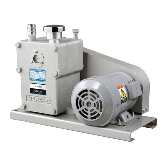
- Page 1 SK00-4167-DI-002-07 INSTRUCTION MANUAL OIL SEALED ROTARY VACUUM PUMP PVD-180,PVD-180B PVD-360,PVD-360B Before using this product, be sure to read this operation manual. Keep this manual with care to use at any time. ULVAC, Inc. Components Division http://www.ulvac.co.jp/...
-
Page 3: Table Of Contents
SK00-4167-DI-002-07 Table of Contents Types and Descriptions of Warning Labels Displayed on The Pump and Displayed Positions ....1 Ⅰ Pump Outline ............................3 Ⅱ Preparation............................6 1. Inspection ............................10 2. Mounting ............................10 3. Lubrication ............................10 4. Electrical Connection ........................11 5. - Page 4 Table 4 Rated current for the standard motor ..................11 Table 5 Standard motor terminal size and protection circuit selection criteria........12 Table 6 PVD-180, PVD-180B, PVD-360, PVD-360B Main replacement parts list ......24 Table 7 PVD-180-H, PVD-360-H Main replacement parts list ............24 Table 8 Performance specifications .......................
-
Page 5: Types And Descriptions Of Warning Labels Displayed On The Pump And Displayed Positions
SK00-4167-DI-002-07 Types and Descriptions of Warning Labels Displayed on The Pump and Displayed Positions Warning labels are attached on the warning locations in this system. Be sure to check them before starting operation of the Pump. Before use, read through the instruction manual and fully understand its contents. - Page 6 SK00-4167-DI-002-07 ・There is a moving part around the section that this warning label is put. ・Do not open a panel or a safety cover during operation. ・You should turn off the power line of the moving part If the power of this Pump doesn’t supply, the moving part may have a possible to move the moving part.
-
Page 7: Ⅰ Pump Outline
Ⅰ Pump Outline 1. Characteristics The PVD-180, PVD-180B, PVD-360 and PVD-360B type oil rotary vacuum pump is a two-stage rotary blade type, compact, robust, easy to use, and designed to withstand a wide range of operating conditions. The ultimate pressure is low, and the vibration and noise associated with operation are sufficiently low. - Page 8 Following specification is available to meet various applications. Table 2 Optional specifications and gasket material/oil type comparison table Applicable Model Gasket material Specification Oil type *1 Oil tank capacity O-ring PVD-180 PVD-180B Oil seal PVD-360 PVD-360B Standard Standard ULVOIL R-72 Spec.
- Page 9 Pa when measured with a McLeod vacuum gauge.) The pump of this type, PVD-180B and 360B have following specific features in comparison with the standard type, PVD-180, -360. 1) The pump [Type: PVD-180B or 360B] has a solenoid valve called Vac. Lock Valve (means Anti Suck Back), when the pump stops the valve shuts off incoming oil and air and keeps a good vacuum for a long period of time.
-
Page 10: Ⅱ Preparation
SK00-4167-DI-002-07 3. Dimensional drawing Fig. 2 Dimensional drawing PVD-180 Dimensional drawing PVD-360 Fig. 3... - Page 11 SK00-4167-DI-002-07 Fig. 4 Dimensional drawing PVD-180B Fig. 5 Dimensional drawing PVD-360B...
- Page 12 SK00-4167-DI-002-07 Fig. 6 Dimensional drawing PVD-180-H+RF-1+RF-7 Fig. 7 Dimensional drawing PVD-360-H+RF-3+RF-8...
- Page 13 SK00-4167-DI-002-07 Fig. 8 Dimensional drawing PVD-180-H+RF-2 Fig. 9 Dimensional drawing PVD-360-H+RF-5...
-
Page 14: Inspection
4) Check for any looseness of screws or nuts or for any disconnection of parts. Note: Should you have noticed any troubles or damages with the pump or its accessories, please contact our local agency or directly to ULVAC International Department. 2. Mounting Please set the pump horizontally on a rigid floor. -
Page 15: Electrical Connection
Table 4 Rated current for the standard motor 200V class Motor Poles:4P ※1 Rated current ( A ) Model Motor 200V/50Hz 200V/60Hz 220V/60Hz PVD-180 0.4kW 2.11 2.00 1.95 PVD-180B PVD-360 0.75kW 3.36... - Page 16 Terminal Earth Thermal Voltage Model Motor breaker or wire ※1 ※ 1 ※ 2 Poles screw screw relay Fuse gauge 1.95A~ PVD-180 0.4kW 0.75mm2 PVD-180B 2.11A 200Vclass 3.02A~ PVD-360 0.75kW 1.25mm2 PVD-360B 3.36A 1.03A~ PVD-180 0.75mm2 0.4kW PVD-180B 1.15A 400Vclass 1.48A ~...
-
Page 17: Connection With Vacuum System
Installation of a vacuum valve, a leak valve and a vacuum gauge between the equipment and the vacuum pump is required for PVD-180 and PVD-360 as shown in Fig.13. When the pump stops, shut the vacuum valve [A] to keep the equipment in vacuum, then open the leak-valve [B] and let air into the pump to prevent from counter-flow of the rotary vacuum pump oil in the pump. - Page 18 Installation of a vacuum valve, a leak valve and a vacuum gauge between the equipment and the vacuum pump is required for PVD-180-H and PVD-360-H as shown in Fig.16. When the pump stops, shut the vacuum valve [A] to keep the equipment in vacuum, then open the leak-valve [B] and let air into the pump to prevent from counter-flow of the rotary vacuum pump oil in the pump.
-
Page 19: Ⅲ Operation
Ⅲ Operation 1. Pump Start Re-check prescribed installations once more and operate your pump as shown Fig.13, PVD-180 and PVD-360, in accordance with the following procedures to obtain the specific performance of the pump. 1) Close the vacuum valve [A] and open the leak valve [B]. -
Page 20: Gas-Ballast Valve
SK00-4167-DI-002-07 3. Gas-ballast Valve This product is installed with the gas ballast function as standard. PVD-180-H, -360-H has no gas ballast valve. Breathed condensed gas shall be liquefied through the compress process of the Pump, mixed with the Pump oil and then cycled mixed together inside the Pump unit. This status brings you the same situation that you used the high steam pressure oil that raises the ultimate pressure. -
Page 21: Oil Mist Trap (Option)
Fig. 17 Mount the oil mist trap to the pump In the case of mounting the oil mist trap to PVD-180-H and PVD-360-H, attach the oil mist trap TMX- 1H on the outlet flange. For more information, please see the instructions of OIL MIST TRAPS. -
Page 22: Pumping Speed
It shall indicate the maximum exhaust speed in the high pressure range and lower speed little by little lower becomes the pressure. PVD-180-H, -360-H has no gas ballast valve. Refer to contents of “Gas Ballast Closed”. Fig. 18 Pumping speed curves... -
Page 23: Power Requirements
SK00-4167-DI-002-07 3. Power Requirements Motive energy to drive the Vacuum pump is a total value of the work of the mechanical element on the rotary friction (mechanical work) and the work of compressing the air (compression work) that becomes maximum when the suction pressure is between 2.7×10 ~ 4×10 Pa. -
Page 24: Ⅴ Maintenance And Check
SK00-4167-DI-002-07 Ⅴ Maintenance and Check 1. Maintenance You should check following points at least once per three days while you continue operation. Check the machine much more frequently during high overload operation (continuous operation at 1000Pa or more, repeated operation between atmospheric pressure and vacuum). 1) Whether the Vacuum oil pump oil volume is between two level lines or not. -
Page 25: Check And Replace V-Belt
SK00-4167-DI-002-07 2-2 Check and Replace V-belt The belt to connect the main body of pump and a motor to is made by rubber. When the belt tension continues driving in an insufficient state… ・The belt is shorten the life-time by the wear. ・The motor is shorten the life time by overheat. - Page 26 SK00-4167-DI-002-07 Measure the tension of the belt 1) Shut down the pump, and be sure to turn OFF the power supply. 2) Remove the belt cover. 3) Set the Ring for Deflection to 5mm. 4) Set the Ring for Load to 0N. 5) Push the center of the belt, between the motor pulley and the pump pulley, down 5mm with tension meter.
-
Page 27: Oil Leak Check
SK00-4167-DI-002-07 2-3 Oil Leak Check The Pump system needs repair if occurred any oil leak from the Shaft sealing or Pump unit. Type of the seals and O-rings are listed at the end of this document. Please contact the Service Center close to you for purchase and repair. -
Page 28: Main Replacement Parts
SK00-4167-DI-002-07 3. Main replacement parts Table 6 PVD-180, PVD-180B, PVD-360, PVD-360B Main replacement parts list Description Model Quantity Oil Seal SC204011 No.6204ZZ Bearing No.6205CM Oil Level Gauge φ35 PVD-180(B) JIS B 2401 P-22A O-ring (Material : NBR) PVD-360(B) JIS B 2401 P-30 . -
Page 29: Trouble Shooting
SK00-4167-DI-002-07 4. Trouble Shooting Table 8 Performance specifications Trouble Causes Processing Method Motor connection is wrong. Check the connection. Safety circuit such as a MS Make the Safety circuit conform to the (Magnetic Switch) is not correctly set. Motor specification. Oil viscosity got higher. - Page 30 Conduct the overhaul of the Pump and Not using the ULVAC genuine oil. replace the oil with the ULVAC oil. New oil pump was just entered. Perform no-load operation for a while. Leak valve is open Close the valve.
- Page 31 SK00-4167-DI-002-07 Trouble Causes Processing Method Do the connection again to correct the Motor rotation direction is reverse. rotation direction. Control the oil level. The oil is not supplied by the Supply the oil by the specified volume. specified volume. Conduct the overhaul. (Replacement of the Pump part) Conduct the overhaul.
- Page 32 SK00-4167-DI-002-07 Trouble Causes Processing Method Deterioration of the O-ring and/or oil Conduct the overhaul. Oil leaks to seal of the Case and Cover. the outside Oil inlet is loose. Tighten again the oil inlet. of the Pump. The drain port is loosening. Re-tighten the drain port.
-
Page 33: Warranty Clauses
This product was shipped after rigid company inspection. However, in case any failure occurs under ULVAC’s responsibility, such as defect in manufacturing and damage during transportation, Buyer shall inform ULVAC, Inc. or the local ULVAC representatives. ULVAC will repair or exchange it at free of charge. - Page 34 (7) Secondary damage by defect of this Product defect. (8) Secondary damage to Buyer by the reason that third party sued ULVAC for patent infringement. (9) ULVAC engineer decided the reason of failure was improper use which does not conform to the use condition of this Product.
- Page 35 This mark is applied to the electronic information product sold in the People's Republic of China. The figure at the center of the mark is the validity date of environmental protection. This product does not influence the environment, the human body and the property during the period reckoning the manufacturing date as long as the caution for safe use regarding the products are observed.
- Page 36 ULVAC service center or sales office prior to shipment. Please consult with your closest local ULVAC service center or sales office if our components are used with toxic gases or contaminated with reactive products or substances produced by reaction.
Need help?
Do you have a question about the PVD-180 and is the answer not in the manual?
Questions and answers