Table of Contents
Advertisement
Quick Links
Advertisement
Table of Contents

Related Manuals for Ulvac PBL Series


Summary of Contents for Ulvac PBL Series
- Page 1 SK00-4813-DI-002-07(No.190628)
- Page 3 Before Using This Pump Thank you for purchasing the oil diffusion ejector pump PBL series (hereafter, "this pump") made by ULVAC (hereinafter, "we"). To ensure safety, upon receiving the pump, confirm that it matches the details of your order and has not been damaged in transit or for another reason.
- Page 4 Safety Indications Signal words and symbol marks are in the warning indications contained in this document and on the product so that the user can understand the matters to be observed. Their meanings are as follows. ■Meanings of signal words Terms that indicate a safe warning level are called signal wards.
- Page 5 Warning Label Types and Display Positions Attach warning labels to the warning locations on this pump. Before operating this pump, be sure to confirm the warning contents. Parts with this warning label have a risk of electrical shock. Turn off the primary power supply before starting wiring or maintenance. Because it becomes very hot, do not touch any section during operation or for some time after operation is stopped.
- Page 6 ■Warning label display positions PBL-02 Fig.1 Warning label attachment position(PBL-02) PBL-04 Fig.2 Warning label attachment position(PBL-04) PBL-06 Fig.3 Warning label attachment position(PBL-06)...
- Page 7 PBL-10 Fig.4 Warning label attachment position(PBL-10) PBL-14 Fig.5 Warning label attachment position(PBL-14) PBL-20 Fig.6 Warning label attachment position(PBL-20)...
- Page 8 We will repair or replace it free of charge。 ■Warranty target Oil diffusion ejector pimp PBL series (PBL-02, PBL-04, PBL-06, PBL-10, PBL-14, PBL-20) ■Warranty period (a) Transactions in Japan: One year from the shipment date.
- Page 9 ■Response (a) Transactions in Japan: We will send a substitute product, or repair the product returned to us or our nearest ULVAC TECHNO office. If on-site action is required, contact our nearest sales office or dealer separately. Direct export transactions: We will send a substitute product, or repair the product returned to us or our nearest service center.
- Page 10 About This Document To ensure this pump remains usable for a long time, before installing, operating, inspecting, or maintaining it, be sure to read this document and fully understand the safety notes as well as the pump's specifications and operating procedures. Note that the specifications, prices, and other contents in this document are subject to change without notice for improvement or other reasons.
-
Page 11: Table Of Contents
Contents Before Using This Pump ・・・・・・・・・・・・・・・・・・・・・・・・・・・・・・・・・・・・・・・・・・ⅰ Safety Indications ・・・・・・・・・・・・・・・・・・・・・・・・・・・・・・・・・・・・・・・・・・・・・・・・・・・・・・・・・・・・・・・・・・・ⅱ Meanings of signal words ・・・・・・・・・・・・・・・・・・・・・・・・・・・・・・・・・・・・・・・・・・・・・・・・・・・・・・・・・・・・ⅱ Meanings of symbol marks ・・・・・・・・・・・・・・・・・・・・・・・・・・・・・・・・・・・・・・・・・・・・・・・・・・・・・・・・・・・・ⅱ Warning Label Types and Display Positions ・・・・・・・・・・・・・・・・・・・・・・・・・・・・・・・・・・・・・・・・・・・・・・ⅲ Warning Label Display Positions ・・・・・・・・・・・・・・・・・・・・・・・・・・・・・・・・・・・・・・・・・・・・・・・・・・・・・・・ⅳ Warranty Terms ・・・・・・・・・・・・・・・・・・・・・・・・・・・・・・・・・・・・・・・・・・・・・・・・・・・・・・・・・・・・・・・・・・・・・・ⅵ Warranty Target ・・・・・・・・・・・・・・・・・・・・・・・・・・・・・・・・・・・・・・・・・・・・・・・・・・・・・・・・・・・・・・・・・・・・・・ⅵ Warranty Period ・・・・・・・・・・・・・・・・・・・・・・・・・・・・・・・・・・・・・・・・・・・・・・・・・・・・・・・・・・・・・・・・・・・・・ⅵ Warranty Scope ・・・・・・・・・・・・・・・・・・・・・・・・・・・・・・・・・・・・・・・・・・・・・・・・・・・・・・・・・・・・・・・・・・・・・ⅵ... - Page 12 3. Installation ………………………………………………………………… 10 3.1 Before Installation …………………………………………………………………… 10 3.1.1 Division of roles from shipment to startup ……………………………………………… 10 3.1.2 Storage environment requirements ………………………………………………………… 11 3.1.3 Environment requirements for installation and operation ……………………………… 11 3.2 Unpacking ………………………………………………………………………… 12 3.2.1 Notes on unpacking …………………………………………………………………… 12 3.2.2 Confirmation after unpacking ………………………………………………………...
-
Page 13: To Ensure Safe Use
1. To Ensure Safe Use This chapter describes how to reduce risks as well as which dangerous behaviors must be avoided for each work item. 1.1 Handling of This Pump If you need an overhaul or repair or if you have a problem, contact our nearest service center. This pump can exhaust inert gas (air, nitrogen, or argon). -
Page 14: Acceptance, Transport, And Storage
Exchange and Foreign Trade Law as well as government ordinances, ministerial ordinances, notices, and other orders based on said law. Contact our nearest sales office or dealer. [List of sales offices] https://www.ulvac.co.jp/support_info/sales_office/ 1.2 Acceptance, Transport, and Storage 1.2.1 Acceptance Never get under this pump. -
Page 15: Storage
1.2.3 Storage Respect the environment requirements. This pump is a machine with a precise clearance. Confirm that the storage location satisfies the requirements listed in "3.1.2 Storage environment requirements." 1.3 Installation and Operation Before installing or removing this pump, separate all energy sources (including power and cooling water) from it. -
Page 16: Disposal
1.4 Disposal Ask a waste disposal specialist to dispose of this pump if you have used it to exhaust harmful gas that may endanger human health. Ask a waste disposal specialist to dispose of this pump if you have used it to exhaust harmful gas that may endanger human health. -
Page 17: Transport Of Heavy Objects
1.6.2 Transport of heavy objects Never get under this pump. The pump may fall or topple if a forcible operation is performed or if the equipment is not sufficiently maintained. Never get under this pump. Never perform loading work or operate the cargo-handling machine if you do not have the appropriate certifications. -
Page 18: Leakage Of Hot Cooling Water
Do not use a chemical substance (lubricant) not specified in this document. Pump fluid ULVOIL B-6 (ULVAC) The SDS describes the chemical substances that may be used or touched to operate this pump. To understand the characteristics of hazards, carefully read the SDS. Obtain the latest version of the SDS from our nearest sales office or dealer. -
Page 19: Product Overview
2. Product Overview The exhaust principles of the oil diffusion vacuum pump are as follows. Diffusion pumps use a high speed jet of vapor to direct gas molecules in the pump throat down into the bottom of the pump and out the exhaust. The diffusion ejector pumps are designed to operate with the ULVOIL B-6 diffusion ejector pump oil. -
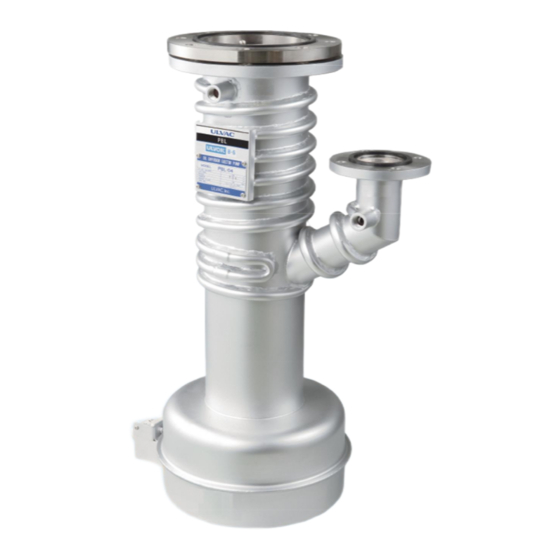
Page 20: Part Names
2.3 Part Names PBL-02 Cooling water inlet Inlet Nameplate Outlet Cartridge heater Cooling Boiler water outlet Terminal Inside of heater case Heater case PBL-04 Inlet Cooling water inlet Nameplate Outlet Cooling water outlet Boiler Nichrome wire Plug type code inlet Inside of Nichrome wire heater Nichrome wire heater PBL-06... - Page 21 PBL-10 Cooling water inlet Inlet Nameplate Outlet Oil level gauge Boiler Cooling water outlet Oil drain port Pipe heater PBL-14 Cooling water inlet Inlet Nameplate Outlet Boiler Oil level gauge Cooling water outlet Oil drain port Pipe heater PBL-20 吸気口 Cooling water inlet Nameplate 排気口...
-
Page 22: Installation
However, the customer may fully or partly transport, unpack, or install this pump depending on the pump's terms and conditions. Packing - ULVAC Transport - ULVAC entrusts this task to a specified carrier. - Customer Cargo reception and unpacking Inspection - Customer... -
Page 23: Storage Environment Requirements
3.1.2 Storage environment requirements When storing this pump (prior to installation) in a warehouse or lobby, or when you will not be using it for a long time, store it so that the following requirements are satisfied. Ambient temperature -20°C to 60°C (no freezing) Ambient humidity 95% RH or less (no condensation) Altitude... -
Page 24: Unpacking
3.2 Unpacking This pump is protected with stretch film, a buffer, or other materials and is packaged in a wooden crate or cardboard box upon shipment. If this pump has been packaged in a wooden crate, ask a specialist to disassemble the crate. Provide the following notes and instructions to the company you ask to perform unpacking. -
Page 25: Transport
Table1 List standard accessories Product name Specifications Qty. Remarks Attached to PBL-02 and PBL-04 ULVOIL B-6 Pump fluid (PBL-06, PBL-10, PBL-14 and PBL-02:0.1L、 PBL-04:0.6L PBL-20 e filled up with.) Heat Shrink Tubing SUMITUBE FZ φ40 L=65mm Attached to only PBL-04 Instruction Manual Japanese and English 3.3 Transport... -
Page 26: How To Transport This Pump Via Pallet Truck
3.3.2 How to transport this pump via pallet truck Always use a pallet when transporting via a pallet truck. Do not transport this pump by pallet truck without placing it on a pallet. Otherwise, this pump may topple, causing injury or damage. 3.4 Installation/Piping 3.4.1 Preparations before installation Inlet port and exhaust port of this pump closes the cover so that a dust, garbage is not... -
Page 27: Cooling Water Piping
3.5 Cooling water piping Please lay pipes in each connection port using an adapted coupling. Use an appropriate joint. This pump's cooling water port is Rc3/8. Connect the cooling water piping to it using an appropriate joint. Do not confuse the cooling water inlet with the cooling water outlet. - Page 28 ● Install a flowmeter (e.g., flow sight) on the cooling water supply source. To check the flow, install a flowmeter that can be used to visually recognize that cooling water is flowing (e.g., flow sight) on the cooling water supply source of the equipment or other device. ●...
-
Page 29: Power Wiring
■ Compatible piping Joints and piping that have water pressure resistance of at least 0.9 MPa The heat resistance must be at least 70°C. Table 4 Piping specifications Supply pressure (MPa) ≦ 0.5 Differential pressure at ports (MPa) PBL-02 PBL-04 PBL-06 Cooling water >... - Page 30 ● Use wire compatible with your local safety codes (e.g. UL, TUV compatible). In addition, use a heat-resistant wire (LKGB, KGB) by all means. ● With reference to a Table 5, prepare for power supply capacity to the power supply specifications of this pump.
- Page 31 Heat-shrinkable tubing SUMITUBE FZ φ40 L=65, Black SUMITOMO ELECTRIC FINE POLYMER, INC. Fig 9 PBL-04 Primary side of the plug type cord...
-
Page 32: Pump Fluid Installation
3.7 Pump fluid installation It is attached to PBL-02 and PBL-04 fluid. As for PBL-06, PBL-10, PBL-14 and PBL-20, fluid is in the pump. Please confirm that fluid is contained by the fluid level gauge. Do not use the fluorine oil. Please never use the fluorine-based oil. -
Page 33: Operation
4. Operation 4.1 Precautions for operation Only suction for inert gases. This pump is designed to exhaust only inert gases (air, nitrogen, or argon). It cannot be used to exhaust other gases (toxic, combustible, corrosive, or explosive gas, or gas that increases the susceptibility of substances) because such gas may leak from the pump's main unit or ignite or explode inside the pump. - Page 34 ● We recommend using water that contains few impurities (e.g., industrial water; refer to the table below). We recommend using water that contains few impurities as cooling water for this pump (e.g., refer to Table 9 [Reference] Standard Quality of Industrial Water in Japan).
-
Page 35: Preparation For Operation
4.2 How to operation FIG. 10 shows a use example of general oil diffusion ejector pump. The operation of this case, please reach as follows. (1) Close the valve 1 and valve 2, and please exhaust oil diffusion ejector pump to 13-1.3 Pa in the oil rotary vacuum pump. -
Page 36: Leak Test
4.3 Leak Test the system After you have installed the pump, leak test the system and seal any leaks found. The level of leak tightness required will depend on the application of the system. You must leak test the system to ensure the integrity of the system and its vacuum seal. 4.4 How to Stop the Pump (1) Close the valve 1. - Page 37 Do not damage the seal surface. The handling, be careful not to damage it to the aspect per gasket of the flange part and a gasket in particular. Please confirm that the temperature of the pump reaches room temperature. 5.2.1 In case of pipe heater (PBL-06、PBL-10、PBL-14、PBL-20) 1) Put off the switch for heater.
-
Page 38: Exchange The Fluid
In the case of AC200V, a power supply, please connect the conducting wire of the heater and the connection to the terminal tandemly. Also, in the case of AC100V, please connect it in parallel.( In case of PBL-02. ) 5.3 Exchange the fluid If the pump fails to give satisfactory performance on a leak tight system, inspect the condition of the pump fluid. -
Page 39: Troubleshooting
6. Troubleshooting Symptom Check Action Is there a leak in the system? Check and rectify. Is the pump fluid level too Check and rectify. low? Is the switch of the heater not turned on? Is the heater Check and rectify. snapped? Is the heater input low? Poor ultimate pressure... -
Page 40: Specifications
7. Specifications 7.1 Technical Data Model PBL-02 PBL-04 PBL-06 PBL-10 PBL-14 PBL-20 Pumping speed (l/s) 1800 4000 7000 Ultimate pressure (Pa) 2.7 × 10 Max. permissible forevacuum pressure (Pa) Lubricant ULVOIL B-6 Pump fluid filling (L) Ambient temperature (°C) 10 to 40 Mains connection 50/60 Hz (V) 200 ~ 1 Ph 200 ~ 3 Ph... -
Page 41: Dimensional Drawings
Cooling water inlet Cooling water 0utlet Cooling water 0utlet Cooling water 0utlet Cooling water inlet Cooling water inlet Cooling water inlet Cooling water 0utlet Inside cooling water port Cooling Cooling water 0utlet water 0utlet Fig. 11 Dimensional drawing for the PBL series... - Page 42 A (mm) 1321 1687 2320 Distance B (mm) between the C (mm) port Rc1/2”×3 Cooling water port Inside Rc1/2”×2 Rc1/2”×3 cooling (size × number of system) Rc3/8” water port ( Fig11 Dimensional drawing for the PBL series Appended chart )
-
Page 43: Appendix
Appendix Major replacement Parts (1) Heater list Table 6 Heater List Model Qty. Specification Shape PBL-02 200V 1φ 0.44 kW Cartridge PBL-04 200V 1φ 1.8 kW Nichrome wire heater PBL-06 200V 3φ 2.0 kW Pipe heater PBL-10 200V 3φ 4.0 kW Pipe heater PBL-14 200V... - Page 44 (3) Gasket List Table 8 Gasket list Model Part name Material Qty. Shape Dimension Standard No. Inlet gasket PBL-02 φ70×φ80×5t Baffle gasket φ120×φ130×5t Inlet gasket PBL-04 φ120×φ130×5t Outlet gasket φ55×φ65×5t Baffle gasket φ175×φ185×5t Inlet gasket φ175×φ185×5t Outlet gasket φ70×φ80×5t PBL-06 Oil filling port gasket JIS 2401 P18 Drain gasket...
Need help?
Do you have a question about the PBL Series and is the answer not in the manual?
Questions and answers