Table of Contents
Advertisement
Quick Links
Advertisement
Table of Contents

Related Manuals for GARDASOFT PP610


Summary of Contents for GARDASOFT PP610
- Page 1 PP610/612 LED Lighting Controllers Issue 015 User manual www.gardasoft.com...
- Page 2 Deliberate acts of endangerment and vandalism are not covered by this document and must be considered by the installer. While care has been taken in the preparation of this document Gardasoft Vision Ltd will not accept any liability for consequential loss of any kind except those required by law.
-
Page 3: Table Of Contents
PP610/612 LED lighting controllers - User Manual Contents Getting started Safety Heat Electrical General Installation guidance (disclaimer) Sicherheit Wärme Elektrik Allgemein Installationsanleitung (Haftungsausschluss) Sécurité Chaleur Électricité Généralités Guide d'installation (clause de non-responsabilité) General description Mechanical fixing PP610 heat output Heat output per channel... - Page 4 PP610/612 LED lighting controllers - User Manual 10.4 Pulsed mode output Reference information Timings 12.1 Selected continuous mode 12.2 Pulse mode Error codes...
-
Page 5: Getting Started
Section 11, Reference information, and check the PP610 fulfils your requirements. Connect the PP610 up to a supply and an LED lighting unit as described in Section 8, Connections. Note that the supply voltage must be connected to three terminals. When the PP610 powers up, it should show two alternating lines on the display to indicate that it is operating properly. -
Page 6: Safety
Reference information). At its maximum ratings, the PP610's enclosure can exceed 75°C which is sufficient to cause a burn if touched. Place in a position where personnel cannot accidentally touch it and ensure there is a free flow of air around the unit. -
Page 7: General
General The PP610 must not be used in an application where its failure could cause a danger to personal health or damage to other equipment. If the equipment is used in a manner not specified by the manufacturer, the protection provided by the equipment may be impaired. -
Page 8: Sicherheit
Berührung durch das Personal ausgeschlossen ist und stellen Sie sicher, dass Luft frei um das Gerät zirkulieren kann. Elektrik Das PP610 erzeugt Impulse mit hoher Energie. Achten Sie darauf, die Ausgänge korrekt anzuschließen und schützen Sie die Ausgangsverkabelung und Last gegen Kurzschlüsse. Beim Ausschalten bleibt Energie für etwa 15 Sekunden im PP610 gespeichert. - Page 9 Schalter als Teil der Installation in der Nähe vorsehen, mit dem die Steuerung an beiden Stromleitern von ihrer Stromquelle getrennt werden kann. Durch induktive Lasten verursachte Einschaltstöße zum PP610 müssen extern unterdrückt werden. Warnung: Es handelt sich hierbei um ein Produkt der Klasse A. Die Verwendung in Wohngebieten kann zu Funkstörungen führen und eine...
-
Page 10: Allgemein
PP610/612 LED lighting controllers - User Manual Allgemein Das PP610 darf nicht in Anwendungen eingesetzt werden, bei denen es durch einen Ausfall des Geräts zu einer Gefahr für die Gesundheit von Personen oder zur Beschädigung anderer Geräte kommen könnte. Wenn das Gerät in einer anderen als der vom Hersteller vorgesehenen Weise verwendet wird, kann die Schutzvorrichtung des Geräts... -
Page 11: Sécurité
PP610/612 LED lighting controllers - User Manual Sécurité Lisez ce document avant d'utiliser le PP610 Respectez les mesures de sécurité suivantes en toutes circonstances. En cas de doute, contactez votre distributeur ou Gardasoft Vision. Les symboles ci-dessous auront la signification suivante:... -
Page 12: Généralités
émissions à un niveau qui permet la réception des transmissions diffusées. Généralités Le PP610 ne doit pas être utilisé dans une application où la santé des personnes et l'intégrité des équipements seraient mises en danger s'il venait à tomber en panne. -
Page 13: Guide D'installation (Clause De Non-Responsabilité)
Ces informations sont seulement à titre indicatif. Les installateurs doivent effectuer leur propre évaluation des risques, pour chaque installation. Même si Gardasoft Vision Ltd a préparé minutieusement ces conseils, Gardasoft Vision Ltd décline toute responsabilité pour tout dommage, quel qu'il soit, à l'exception de ceux requis par la loi. La mise en péril volontaire ainsi que les actes de vandalisme ne sont pas couverts par le présent document et doivent être pris en compte par l’installateur. -
Page 14: General Description
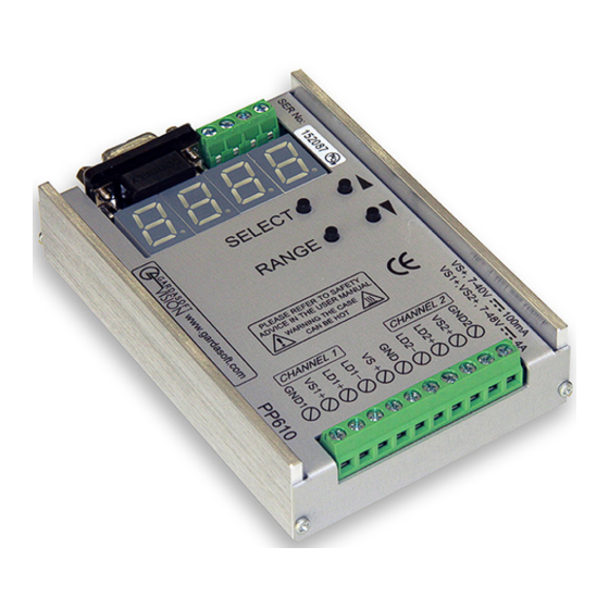
In this mode output is pulsed once per trigger. One input is used as a trigger. The delay and pulse duration can range from 20µs to 1 second in 20µs or 2ms steps. The PP610 can be set up using four push buttons and a four digit seven- segment display (see Section 9, Operation). -
Page 15: Mechanical Fixing
The thickness of the base is 3.2mm. Fixing screws must not extend into the enclosure by more than 6mm. The enclosure of the PP610 is used to dissipate power in the form of heat. For this reason the material to which the unit is attached must be suitable, preferably metallic with ability to dissipate the produced heat. - Page 16 To limit the power, set the power supply output voltages to the minimum value required by the LED light and the PP610 together. Chose a PSU that limits its output current by design, by setting the current limit on the supply (if this feature exists) or use fuses.
-
Page 17: Pp610 Heat Output
PP610/612 LED lighting controllers - User Manual PP610 heat output The PP610 controller has a linear circuit to produce constant current output. This section explains how to calculate the heat output from the PP610 and what measures you can take to manage it. -
Page 18: Total Heat Output
PP610/612 LED lighting controllers - User Manual Total heat output The total heat output from the PP610 is given by adding the heat output for both channels as calculated above. If the heat output is no greater than 10W, no heatsinking is required. If the heat output is between 10W and 24W, the PP610 needs to be mounted on a solid piece of metal to dissipate the heat. -
Page 19: Connections
PP610/612 LED lighting controllers - User Manual Connections All connections except RS232 are made on screw terminals. The opto- isolated inputs require a voltage between 4.5v and 24v DC for a positive logic level. Open circuit or less than 1v gives a negative logic level. -
Page 20: Pp610 Serial Connector
PP610 and PP612 controllers are fitted with a standard 9-way D-sub female connector for RS232 communications. The connections are shown in the diagram below: A standard straight through cable can be used to connect the PP610 or PP612 controller to a PC serial port. —... -
Page 21: Pp612 Ccs Connectors
PP610/612 LED lighting controllers - User Manual PP612 CCS connectors PP612 controllers are additionally fitted with connectors for CCS lights. Note that the power input and digital inputs are only available on the screw terminals. The connectors are not labelled on the case. Refer to the table below and the diagram overleaf for the layout. -
Page 22: Power Supply
= Rated voltage in Volts Power supply The PP610 has split power input connectors for the control circuit and the two output channels. This is so that crosstalk between the outputs can be minimised when one channel has a high output current. - Page 23 PP610/612 LED lighting controllers - User Manual Note: A PP600 is shown in these illustrations. The same power connections apply for a PP610 or PP612. — —...
-
Page 24: Split Supply Applications
PP610/612 LED lighting controllers - User Manual 8.3.2 Split supply applications It is possible to run the two channels and digital system from two or three separate supplies as shown below, though this will rarely be necessary. Note: It is essential that the ground of the three supplies are commoned close to the PP610. -
Page 25: Operation
PP610/612 LED lighting controllers - User Manual Operation The PP610 can be set up using the push buttons and display on the front of the unit. The setup is non-volatile, so the PP610 will resume the same operation after a power cycle. -
Page 26: Pulsed Output
The output is off by default. When a trigger is received on one of the digital inputs, the PP610 will wait for a delay period and then pulse the output. The delay period, pulse width and pulse current are all configurable. -
Page 27: Current Protection
Note that after a cold boot (and the factory default) the maximum rating is set to 4A. 9.3.5 Setting numeric values When the PP610 displays numeric values for the user to change, the right hand digit flashes to indicate that the buttons can be used to change the lowest digit. Pressing the... -
Page 28: Setting Pulsed Operation
The PP610 sets the output current. 9.4.2 Setting pulsed operation Pulsed output on a PP610 controller can be set up using Simple Set-Up. Set up pulsed mode as follows: The PP610 is ready. Press and hold SELECT for one second. - Page 29 PP610/612 LED lighting controllers - User Manual Use the buttons to select which output channel to set up - CH1 or CH2. Press SELECT. Use the buttons to select PU1 to trigger from INPUT1 or PU2 to trigger from INPUT2. DEL is displayed. Wait for one second...
- Page 30 Section 9.3.5, Setting numeric values. Press SELECT. dONE is displayed for one second. The PP610 is ready to pulse the output on a trigger. When the lights are pulsed, the display shows that a trigger has occurred as follows: The PP610 is ready.
-
Page 31: Extended Set -Up
The PP610 shows that one of the channels is being pulsed. The PP610 is ready. Extended Set -Up Extended Set-Up allows all features of the PP610 to be set up. It is entered by holding the RANGE button down for one second. -
Page 32: Setting Continuous Output (Extended)
PP610/612 LED lighting controllers - User Manual 9.5.1 Setting continuous output (extended) Set continuous output on a PP610 as follows: The PP610 is ready. Press and hold RANGE one second. Use the buttons to select which output channel to set up - CH1 or CH2. - Page 33 PP610/612 LED lighting controllers - User Manual Use the buttons to select C0 to enter the current in Amps (a), or C-3 to enter the current in milliamps (b). Press SELECT. Use the buttons to select the required current in Amps (a), or milliamps (b).
-
Page 34: Setting Pulsed Output (Extended)
PP610/612 LED lighting controllers - User Manual 9.5.2 Setting pulsed output (extended) Set pulsed operation on a PP610 as follows: The PP610 is ready. Press and hold RANGE one second. Use the buttons to select which output channel to set up - CH1 or CH2. - Page 35 PP610/612 LED lighting controllers - User Manual Use the buttons to select d0 to enter the delay in seconds (a), or d-3 to enter the delay in milliseconds (b). Press SELECT. Use the buttons to select the required delay in seconds (a), or milliseconds (b).
- Page 36 PP610/612 LED lighting controllers - User Manual Use the buttons to select P0 to enter the pulse width in seconds (a), or P-3 to enter the pulse width in milliseconds (b). Press SELECT. Use the buttons to select the required pulse width in seconds (a), or milliseconds (b).
- Page 37 (a), or milliamps (b). Note: Refer to: Section 9.3.5, Setting numeric values. Press SELECT. dONE is displayed for one second. The PP610 is ready to pulse the output on a trigger. — —...
-
Page 38: Pp610 Command Structure
The command codes and their meaning are described below. The single upper case letter codes for the parameters are also shown, followed by lower case letters denoting the numeric argument. All responses from the PP610 and PP612 are terminated with a > character to indicate that the transaction is complete. -
Page 39: General Commands
PP610/612 LED lighting controllers - User Manual Unrecognised command or parameters. Illegal mode or channel number in command Commands take effect immediately they are issued. Because of this, if the settings are being changed from high current pulsed output mode to a continuous output mode, it is advisable to set the current values to 0 using the RC command before changing mode. - Page 40 PP610/612 LED lighting controllers - User Manual output current 4 maximum current rating of LEDs pulse width (in milliseconds) delay before pulse (in milliseconds) The third line is for factory use. The fourth and fifth lines are the de-bounce period for each input:...
-
Page 41: Continuous Output Mode
PP610/612 LED lighting controllers - User Manual Report the firmware version This command returns the current firmware version running in the running in the PP610/PP612. 10.2 Continuous output mode These commands set the mode of operation and define the current output value. - Page 42 PP610/612 LED lighting controllers - User Manual Set the mode of operation RSfSm Where: output channel (1 or 2). 4 for two currents selected using input 1 5 for two currents selected using input 2 6 for four currents selected using both inputs...
- Page 43 PP610/612 LED lighting controllers - User Manual 10.4 Pulsed mode output These commands set the trigger source mode for pulsing, the pulse width and delay. Set the pulse parameters RTfMmPpDd Where: output channel (1 or 2) 1 to trigger on input 1...
- Page 44 PP610/612 LED lighting controllers - User Manual Set the output current RCfCcVvEe Where: output channel (1 or 2) output selection. Set to 0 for non-selected operation. output current (in milliamps) maximum current rating of the LED. This is optional; if not required, omit Ee from the command.
- Page 45 PP610/612 LED lighting controllers - User Manual Reference information Parameter Value Notes Digital supply 7VDC (min) Ideally set this voltage as low as voltage (VS+) 40VDC (max) possible to reduce the total unit regulated power dissipation. Digital supply 125mA (max) current...
- Page 46 PP610/612 LED lighting controllers - User Manual Timings 12.1 Selected continuous mode When using selected continuous mode, the maximum delay from an input changing to the output current changing is 500µs. 12.2 Pulse mode For short delays and pulse widths, the actual timings are repeatable but not exact.
- Page 47 PP610/612 LED lighting controllers - User Manual Error codes Error codes may be displayed by the PP610. These are in the form E nn, where nn gives the number of the error. To cancel the error message, press SELECT. The error codes are given in the table below:...
- Page 48 PP610/612 LED lighting controllers - User Manual Code Meaning An internal software error has occurred. Make a note of the number and contact your distributor. — —...
- Page 49 PP610/612 LED lighting controllers - User Manual This page is left blank for your notes: — —...
- Page 50 PP610/612 LED lighting controllers - User Manual Issue v015 - May 2017 © Copyright 2017 Gardasoft Vision Ltd Gardasoft LLC Gardasoft Vision Ltd Oak Ridge Road Trinity Court Weare Buckingway Business Park New Hampshire Cambridge CB24 4UQ UK 03281 USA tel: +44 1954 234970...
Need help?
Do you have a question about the PP610 and is the answer not in the manual?
Questions and answers