Table of Contents
Advertisement
Quick Links
Advertisement
Table of Contents
Troubleshooting

Subscribe to Our Youtube Channel
Related Manuals for Dover markem-image 9020


Summary of Contents for Dover markem-image 9020
- Page 1 Book for service engineers internal use only...
-
Page 3: Contents
Contents A36163-C.doc 3/189... - Page 4 Contents Notes: A36163-C.doc 4/189...
-
Page 5: Table Of Contents
Contents CONTENTS SAFETY ■ R EMINDER ■ S UPPLEMENT FOR ARKEM MAJE SERVICE ENGINEERS ESPONSIBILITY EALTH AND SAFETY IRE PREVENTION NVIRONMENT YSTEM ANDLING ERVICING TROUBLESHOOTING ONSUMABLES AFETY EQUIPMENT FOR ARKEM MAJE SERVICE ENGINEERS ULES OF CONDUCT FOR ARKEM MAJE SERVICE ENGINEERS WHEN VISITING CUSTOMERS PRINTER DESCRIPTION ■... - Page 6 Contents 2: I NSTALLATION PREPARATION 3: I NSTALLATION 4: B ASIC INSTRUCTION 5: I NSTALLATION VALIDATION ■ F IRST PRINTER START ■ O PERATOR NFORMATION AILY START ■ C USTOMER TRAINING BJECTIVES OW CUSTOMER TRAINING CAN HELP REACHING OBJECTIVES USTOMER TRAINING CONTENT ELIVERABLES AFTER SALES SERVICE POLICY ■...
- Page 7 Contents ELEASING VALVE ARTIAL DRAIN ULL DRAIN IC60 NK CIRCUIT RINSING CALIBRATION ■ L IST OF SPECIAL SPARE PARTS FOR ARKEM MAJE ERVICE NGINEERS ■ L IST OF THE SPARE PARTS FOR CUSTOMERS ■ S PARE PARTS SHEETS ODULATION ASSEMBLY REPLACEMENT ESONATOR REPLACEMENT VALVES BLOCK REPLACEMENT UTTER ASSEMBLY REPLACEMENT...
- Page 8 Contents ■ P RINT HEAD ■ D IAGRAM OF RECOVERY GUTTER SOLENOID VALVE ■ R ECOVERY GUTTER ■ P RINCIPLE OF TRANSFERS ■ I NK FILTERS ■ M AKE UP FILTER ■ C ALIBRATED TUBES RESTRICTION ■ C ONSTANT INK CONCENTRATION PRINCIPLE ■...
- Page 9 Contents ALCULATION OF THE MAXIMUM SPEED OF AN ALGO SING RESTRICTION LGORITHM TABLE CURVPRINT LGOS CURVPRINT. SPEEDS TABLE ■ P RINTING PRESSURE SPEED ONTROLLING THE QUALITY OF INK NK PRESSURE ■ A TMOSPHERIC PRESSURE ABSOLUTE PRESSURE RELATIVE PRESSURE TMOSPHERIC PRESSURE BSOLUTE PRESSURE ELATIVE PRESSURE RESSURE IN A LIQUID...
- Page 10 Contents Notes: A36163-C.doc 10/189...
-
Page 11: Safety
Safety A36163-C.doc 11/189... - Page 12 A36163-C.doc 12/189...
-
Page 13: Reminder
Safety ■ Reminder Please read all the safety instructions included in the Markem-imaje user manuals provided to customers. ■ Supplement for Markem-Imaje service engineers Responsibility Printers must not be modified by customers without the validation of Markem- Imaje. Printers must be used according with the specifications of the user manual. . Health and safety The safety data sheet (SDS) on the following pages is provided as an example only. -
Page 14: Fire Prevention
Safety Do note touch electronic boards if the printer is not disconnected from the main power. Fire prevention Follow the instructions on the safety data sheet (SDS) for each MI consumables Have a foam, CO2, or powder fire extinguisher placed close to the printer area (distance of 10 meters maximum). -
Page 15: Environment
Safety NO SMOKING – FLAMMABLE INK Always keep away from open flame. Never smoke near the printer. Place a sign with the follow information “NO SMOKING – FLAMMABLE INK” near the printer. Containers of ink, additive and cleaning solution must be closed and stored in a ventilated place or an adapted cabinet. -
Page 16: Consumables
Safety Consumables Consumables and the printer The Markem-Imaje printer is delivered with the right consumables according with the ink type selected by the customer. We strongly advise to do not replace the ink type. Markem-Imaje equipment is guaranteed. In order to have a correct printer management, use always the Markem-Imaje consumables appropriated. -
Page 17: Printer Description
Printer Description A36163-C.doc 17/189... - Page 18 Printer description Notes: A36163-C.doc 18/189...
-
Page 19: Introduction
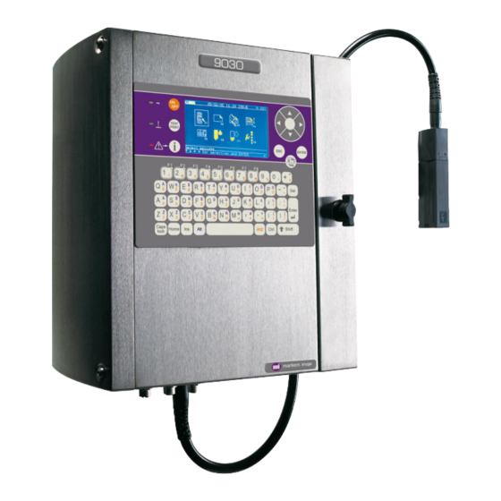
Printer description ■ Introduction Two printer versions are available: Markem-Imaje 9020 Markem-Imaje 9030 9020 is available in one configuration: IP 54, mono-print head, single jet, G type. 9020 key points: Ergonomic operator interface Easy management and access to the consumable cartridges PCMCIA card for back up Logo creation Up to 4 lines... -
Page 20: Cabinet
Printer description ■ Cabinet 9020 and 9030 are composed of a cabinet and a print head linked by a 3 meter umbilical. Front view Rear view (with printer holder) The cabinet must be installed vertically by the fixing points located on the rear side A distance of 90mm (MI support deep) is necessary between the back of the printer and the stand (wall) this allow to open correctly the right door. - Page 21 Printer description The cabinet is very compact, the dimensions are: Height: 400 mm Width: 367 mm Depth: 239 mm Volume 35 dm (35 litres) Weight: is less than 20 kg (depending on options installed and cartridges status) A36163-C.doc 21/189...
- Page 22 Printer description The electrical connections (power supply, industrial inputs/outputs, V24…), pneumatic connections (air pressurisation, vapours extraction…) and umbilical are located at the bottom of the cabinet. Important : The printer must run with the doors closed. A36163-C.doc 22/189...
-
Page 23: Operator Interface
Printer description ■ Operator Interface The operator interface is user friendly thanks to • A screen with icons for daily operations & consumables level indication • Windows-type menu structure • Help message to guide the operator through the different menu levels •... - Page 24 Printer description Examples: beng, chan, li zao, etc. This acquisition is incremental. Examples: B results in 20 ideographs beginning with the sound [b], BE gives10 ideographs beginning with the sound [be], BEN gives 5 ideographs beginning with the sound [ben]. There are some 410 morphemes by which one can enter the "PinYin engine", this corresponds with about 6700 different Chinese characters.
-
Page 25: Print-Head & Umbilical
Printer description ■ Print-Head & Umbilical 9020 print head is available in single jet , G type 9030 print head is available in 2 versions: mono-jet or twin- jets 9030 print head is available in 2 different nozzle sizes: • 72 µ... - Page 26 Printer description Nozzle cleaning During printer start-up & shutdown, make up solution is introduced into the modulation assembly to clean the cavity. During these 2 phases, the gutter solenoid valve is rinsed as well. Important : .The print head level must be set correctly in the “Preparation” menu. The nozzle cleaning sequence is optimised according to the print head level parameter.
- Page 27 Printer description Under the cabinet, the umbilical output is available in 2 configurations: Normal configuration Angled umbilical output configuration Option: A35442 Print Head dimension A36163-C.doc 27/189...
-
Page 28: Electronic Compartment
Printer description ■ Electronic compartment The electronic compartment is located on the left side of the printer. The main electronic elements are: • The mains filter (located under the cabinet) • The power supply board (located at the top of the cabinet) •... - Page 29 Printer description CPU board 2 CPU boards are available. • One version for 9020 Single jet only and less input/output functionality for the industrial interface board. • One version for 9030 The same 9030 CPU board will drive single and twin jets, G or M 9030 printers. The CPU and printing functions are located on the same board.
-
Page 30: Hydraulic Compartment
Printer description ■ Hydraulic compartment The hydraulic compartment is on the right side of the printer. When the operator opens the door on the right, he only has access to the consumable cartridges and the PCMCIA slot. Make up cartridge Ink cartridge PCMCIA/SD card Ink Circuit: IC60... -
Page 31: Industrial Interface Connection Board
Printer description ■ Industrial Interface connection board The industrial interface connection board is located in the electronic compartment, accessible via the left side. There are 2 ways to connect an external device to the printer. For the basic and more common signals (photocell, encoder & alarm), 3 IP65 external M12 connectors are available. - Page 32 Printer description Industrial Interface connection board The Industrial interface connection board allows the connection of external device. 2 types of boards are available. • Industrial interface connection board without Ethernet communication • Industrial interface connection board with Ethernet communication Industrial interface connection board Industrial interface connection board with Ethernet communication A36163-C.doc...
- Page 33 Printer description Inputs / Outputs 9020 9030 Object detection cell input 1 TOP1+ Standard (external Standard (external connector TOP1- connector) or Interface board) Object detector inhibition input INHTOP+ Option (Interface board) Standard (Interface board) INHTOP- Tacky coders input TACHY+ Standard (external Standard (external connector...
- Page 34 Printer description Terminals +24VP ALDEF C ALDEF T ALDEF R OUT- OUT+ INCMES- INCMES+ COMPARA INVMES- INVMES+ ETATIMP+ SENSBIB- ETATIMP- SENSBIB+ SYNCMESS+ TACHY- SYNCMESS- TACHY+ +24VP +24VP TOP1+ A/M- TOP1- A/M+ TOP2+ IN1- TOP2- IN1+ RAZCPT1+ TXDI RAZCPT1- RXDI RAZCPT2+ TXDI+ RAZCPT2- RXD+I...
-
Page 35: General Specification
Printer description ■ General specification Physical characteristics Dimensions (mm) □ Printer cabinet ......400 x 355 x 215 □ Print head (straight)....182 x 36 x 43 □ Consumable cartridge ....250 x 55 x 55 Weight (kg) □ Complete machine ....less than 20 kg □... - Page 36 Printer description Compliance with standard Safety □ Conformity (self-certification): CE marking conforms with the machine directive, the electromagnetic compatibility directive and the low voltage directive: CEI 60950 (UL 60950, EN60950), CEI 60204-1 (EN60204-1). □ Accreditations (third-party bodies): UL label according to UL 60950, CSA label according to CSA C.22.2.950, GS label according to EN 60204-1 and ZH 1/10* EX-RL/03.85.
-
Page 37: Energy
Printer description ■ Energy • 100 - 120V 0.5A alternative (Automatic switching). 200 - 240V 0.3A alternative (Automatic switching). Frequency 50 or 60 Hz Power 60 VA. Main fuse 1.25 AT • Air pressurised (for 9030 IP65) Specifications Value Air quality Max: 0.12 grams of water/m³... - Page 38 Printer description Notes: A36163-C.doc 38/189...
-
Page 39: Pre-Installation Installation Training
Pre-Installation Installation Training A36163-C.doc 39/189... - Page 40 Pre-installation / Installation / Training Notes: A36163-C.doc 40/189...
-
Page 41: Policy
Pre-installation / Installation / Training ■ Policy For each MI proposal for a new application*, the consumable proposal has to be validated by the customer through the print sample process. For each installation project, a Pre-installation has to be performed in order to: •... -
Page 42: Installation Guide
Pre-installation / Installation / Training ■ Installation Guide The most important contact a company can have with the MI technical service department is the first one. Pre-installation or installations have a habit of setting the tone of how a customer views Markem-Imaje. - Page 43 Pre-installation / Installation / Training Step 1: Print sample Customer project Validation validation Pre-installation Step 2: Installation preparation Preparation of the installation Step 3: Installation Physical installation Installation validation Printer back-up Message/font/Config Step 4: Operator instruction Operator instruction Step 5: Validation with Installation validation customer...
-
Page 44: Step 1: Customer Project Validation
Pre-installation / Installation / Training Step 1: Customer project validation Print samples process & Sampling activity The sampling activity is a free service offered to external and internal customer for validation of suitability of inks for clearly identified applications. For each MI proposal concerning a new application or new substrate, the ink choice has to be validated by the customer through the print sample process. -
Page 45: Step 2: Installation Preparation
Pre-installation / Installation / Training Step 2: Installation preparation In order to perform an efficient and professional installation, the installation has to be strongly prepared to avoid any surprise during the installation. Several points have to be checked during this preparation; Contact your sales &... -
Page 46: Step 3: Installation
Pre-installation / Installation / Training Step 3: Installation Arriving at customer site & installation Meet your contact and confirm the plan for the installation • Confirm the plan for the installation according to your last exchange with your contact and with the information present in the Pre-installation form. •... -
Page 47: Step 4: Basic Instruction
Pre-installation / Installation / Training Installation validation When the physical installation is performed, please use the “Installation validation checklist” in order to control the installation rules for the CIJ technology. Once the installation is definitive, validate the message layout in production condition. Once the message layout is validated, start a production follow-up. -
Page 48: First Printer Start-Up
Pre-installation / Installation / Training ■ First printer start-up □ Plug the AC power cord provided with the printer into a power outlet (do not modify it): Female plug into printer and rubber blanking cap Male plug into a standard outlet (2 poles, grounded) □... -
Page 49: Operator Information
Pre-installation / Installation / Training ■ Operator Information Daily start-up □ Press the On/Off button (press twice if screen is off). □ Press ENTER to confirm. The ink circuit and the jet start up automatically. The printer is ready to print when the green “Head Status” LED is lit steady. Start-up time: approx. -
Page 50: Customer Training Content
Pre-installation / Installation / Training Customer training content CTP 9020-9030 – Training Objectives Map Technical Operator & Technician Customer staff Basic Advanced Technical Training Short Basic Training Training Training objectives/contents Instruction* Course Course Course Safety rules MI group presentation + local organisation Vocabulary linked to the printer Ink jet technology Start-up and shut-down... -
Page 51: Deliverables
Pre-installation / Installation / Training Deliverables All deliverables are written in English only and available on Planet. Translation will be done locally. The CTP A37768-B (Customer Training Package) includes: • Basic Training Course • Advanced Training Course • Technical Training Course Note: The flipchart “Short Basic Instruction”... - Page 52 Pre-installation / Installation / Training Notes: A36163-C.doc 52/189...
-
Page 53: After Sales Service Policy
After sales service policy A36163-C.doc 53/189... - Page 54 After sales service policy Notes: A36163-C.doc 54/189...
-
Page 55: Access Maintenance Agreement
After Sales Service Policy ■ ACCESS maintenance agreement Purpose: List of points to be checked during ACCESS maintenance agreement 9020 / 9030 1 - General information Customer name: ___________________________ Date : ___________________________ Town : ___________________________ Printer serial no. : ___________________________ Contact name : ___________________________ Visit report no. - Page 56 After Sales Service Policy 4 – Operational check before maintenance Not OK Comments User interface functioning ____________________________________ Printer start-up ____________________________________ Jet centered and stable ____________________________________ No recovery gutter overflow ____________________________________ Break-off point setting ____________________________________ Jet speed differential jet1 to jet 2 < 1m/s ____________________________________ Pref: ______b Pacc: ______b T: ______°...
- Page 57 After Sales Service Policy 5 – Parts replaced Pressurization kit filter Part Location Part number: ENM16203 Location: left side of the printer Part cabinet replaced Replacement: 6 months * * depends on the quality of the air and can be adjusted accordingly Quantity: 1 Air filters ** Part...
- Page 58 After Sales Service Policy 6 – Printer rinsing The printer must be rinsed every two years Last printer rinsing date: ___ / ___ / ___ Rinsing: required Rinsing: complete Not OK Comments: ______________________________________________________________ 7 – Parts replaced (other than those included in the maintenance agreement) Parts replacement Part number Description...
- Page 59 After Sales Service Policy 10 User Comments User knows the safety rules ____________________________________ Printer documentation is available ____________________________________ User knows basic maintenance ____________________________________ procedures User knows how to use the operator ____________________________________ interface User needs training ____________________________________ 11 Maintenance report Comments Maintenance complete ____________________________________...
- Page 60 After Sales Service Policy Appendix: Time schedule We have tried to estimate the time you need for each section. This sheet is for the Markem-Imaje network, but can be given to the customer on request. § Section Approx Comments time (min) General information To be filled in before service Printer information before maintenance...
-
Page 61: Standard Maintenance Agreement
After Sales Service Policy ■ STANDARD maintenance agreement Purpose : List of points to be checked during STANDARD maintenance agreement 9020 / 9030 1 - General information Customer name: ___________________________ Date : ___________________________ Town : ___________________________ Printer serial no. : ___________________________ Contact name : ___________________________ Visit report no. - Page 62 After Sales Service Policy 4 – Operational checks before maintenance Not OK Comments Operator interface functioning ____________________________________ Printer start-up ____________________________________ Jet centered and stable ____________________________________ No recovery gutteroverflow ____________________________________ Break-off point setting ____________________________________ Jet speed differential jet1 to jet 2 < 1m/s ____________________________________ Pref: ______b Pacc: ______b T: ______°...
- Page 63 After Sales Service Policy 5 – Parts replaced Pressurization kit filter Part Location Part number: ENM16203 Location: left side of the printer Part cabinet replaced Replacement: 6 months * * depends on the quality of the air and can be adjusted accordingly Quantity: 1 Air filters ** Part...
- Page 64 After Sales Service Policy Ink circuit** Part Location Part number: related to the ink base Part replaced Location: accessible from the right side door Replacement: 8 000 Hrs (active hours counter) or 4 years Quantity: 1 **: the printer must be rinsed before changing the ink circuit 6 –...
- Page 65 After Sales Service Policy 9 –Operational test after parts replacement and update Not OK Comments Printer start-up ____________________________________ No ink leakage ____________________________________ Ink type setting ____________________________________ Head level setting ____________________________________ Autocalibration ____________________________________ (only if the ink circuit has been changed) Fault checking Not OK Comments...
- Page 66 After Sales Service Policy 11 Maintenance report Comments Maintenance complete ____________________________________ ____________________________________ ____________________________________ ____________________________________ ____________________________________ Action to be taken by Markem-Imaje by ___ / ___ / ___¤ Action to be taken by customer by ___ / ___ / ___ ¤ ¤...
- Page 67 After Sales Service Policy Appendix: Time schedule We have tried to estimate the time you need for each section. This sheet is for the Imaje network, but can be given to the customer on request. § Section Approx Comments time (min) General information To be filled in before service Printer information before maintenance...
- Page 68 After Sales Service Policy Notes: A36163-C.doc 68/189...
-
Page 69: Maintenance
Maintenance A36163-C.doc 69/189... - Page 70 Maintenance Notes: A36163-C.doc 70/189...
-
Page 71: Preventive And Proactive Maintenance Table
Maintenance ■ Preventive and proactive maintenance table Frequency Action Duration Comments 5 min. See “User manual”. When clogging Clean the print head causes the printer to malfunction or to produce poor quality print. 10 min. * Number of hours when the printer 4000 hours* Change the filter of the is connected to the compressed air. -
Page 72: Three Reasons Why 9020/30 Printers Require Maintenance
Maintenance ■ Three reasons why 9020/30 printers require maintenance Ink circuit Mechanical components in the hydraulic system wear down due to repetitive movements (solenoid valves, pumps), rubbing, chemical attack (seals) and temperature variations. Narrow passages (nozzle, leaks or calibrated passages) can become partially clogged with ink particles or dust entering the ink circuit. -
Page 73: To Sum Up
Maintenance ■ To sum up... Ink Circuit - Presence of wear parts Solenoid valves Seals Pumps - Micro-conduit Active chemical Calibrated tubes - Limited life Nozzle - Fast drying - Filters - Sensitive to temperature Main filter variations Grids Ink/printer Ink preparation - Pressure Ink compressed... -
Page 74: Printer Long Stop
Maintenance ■ Printer Long stop Shut-down the printer for a period of less than three weeks □ Press “ON/Off” key. □ Press “ENTER” key to confirm. The printer stops after approx. 30 seconds even if the jet is operating. Shut-down the printer for a period of more than three weeks If the printer is stopped for a period of more than three weeks, it must be drained and rinsed (see draining and rinsing procedure, chapter “Maintenance”... - Page 75 Maintenance ■ Print head operations Jet start-up and shut-down The jet only needs to be stopped when performing maintenance on the print head. Re start the jet after maintenance operation. IMPORTANT: Stop the jet without stop the printer. Cleaning of the print head □...
- Page 76 Maintenance Unblock Nozzle Use this function (Production/Maintenance/Jet Maintenance) when there is no jet or the jet is deviated. Status of the print head solenoid valves during this function Ink EV Drain EV Additive EV Rinsing EV Recovery EV Phase 1 Open Closed Closed...
- Page 77 Maintenance Intro. Cleaning Solution Use this function (Production/Maintenance/Jet Maintenance) when the jet is deviated. Status of the print head solenoid valves during this function Ink EV (A) Drain EV (B) Additive EV Rinsing EV Recovery EV Phase 1 Closed Open Closed Closed Closed...
- Page 78 Maintenance Check Jet Stability Use this function (Production/Maintenance /Jet maintenance) when the jet is unstable. Status of the print head solenoid valves during this function Ink EV (A) Drain EV (B) Additive EV Rinsing EV Recovery EV Phase 1 Open Open Closed Closed...
-
Page 79: Troubleshooting
Troubleshooting A36163-C.doc 79/189... - Page 80 Troubleshooting Notes: A36163-C.doc 80/189...
-
Page 81: Abbreviations Table Used In This Chapter
Troubleshooting ■ Abbreviations table used in this chapter Abbreviation Signification Accu Accumulator Solenoid valve / Electro valve Algo Algorithm Ink Circuit Central Process Unit Cyclic Redundancy Control Print Module Piezo Piezo-electric / Resonator EHT / EHV High tension (voltage) electrode After Sales Services ■... - Page 82 Troubleshooting A / D Description Context Check / Cause / Remedy / Solution Consequences CRC EEPROM The CRC calculated when the printer is switched on is Ink circuit different from the CRC incorrect stored. Consequences: The IC60 time counter information is lost, but the module continues to run as usual.
- Page 83 Troubleshooting A / D Description Context Check / Cause / Remedy / Solution Consequences The data received from the Check the value of the check byte and whether the Incorrect external connection is wrong. identifiers used to communicate with the printer external data exist.
- Page 84 Troubleshooting A / D Description Context Check / Cause / Remedy / Solution Consequences The CRC calculated when Reprogram the messages. CRC(RAM) the printer is switched on is Check the position of the battery jumper on the message different from the CRC CPU.
- Page 85 Troubleshooting A / D Description Context Check / Cause / Remedy / Solution Consequences CRC(RAM) Print Appears after the CPU is Check the position of the battery jumper on the CPU. Incorrect reset. Consequences: Check the voltage of the CPU battery. Stored data (date, time, etc.) Replace the CPU is lost.
- Page 86 Troubleshooting A / D Description Context Check / Cause / Remedy / Solution Consequences Read/write error Impossible to read or write to on CPU EEPROM the CPU EEPROM during operation. Consequences: The ink management parameters are no longer saved. Printer operation disrupted. Print speed above This alarm appears after Change the tachometer division or select algorithms...
- Page 87 Troubleshooting A / D Description Context Check / Cause / Remedy / Solution Consequences LOW INK level. The ink level in the cartridge Cartridge Prepare new is calculated by the software - Small amount of ink remaining in cartridge cartridge using the negative pressure - Correctly positioned in cartridge holder value and the number of...
- Page 88 Troubleshooting A / D Description Context Check / Cause / Remedy / Solution Consequences EMPTY MAKE UP After several attempts to Cartridge Cartridge pump make up from the Not empty cartridge, the printer Correctly positioned in cartridge holder indicates that the cartridge is Properly perforated empty.
- Page 89 Troubleshooting A / D Description Context Check / Cause / Remedy / Solution Consequences EV2: Buffer Incorrect pressure levels Test solenoid valve EV2: solenoid valve measured when ink flows from buffer tank to - If OK: pressure sensor or blocked tube accumulator at start-up or (replace IC60) during operation.
- Page 90 Troubleshooting A / D Description Context Check / Cause / Remedy / Solution Consequences Ink concentration During printing the working Check the following parameters: out of pressure required for proper specifications jet speed is outside the P = Head height difference f(T) curve.
- Page 91 Troubleshooting A / D Description Context Check / Cause / Remedy / Solution Consequences Motor The printer does not detect Test solenoid valves EV0, EV1, EV2, EV3, EV4, EV5, EV6 and EV10. synchronisation sufficient difference in incorrect pressure between the pump top dead centre and the Make sure there is no liquid in the air pump.
- Page 92 Troubleshooting A / D Description Context Check / Cause / Remedy / Solution Consequences Air inflation The time needed to pump air Test solenoid valves EV3 and EV4 timeout into the accumulator during start-up, draining or rinsing is Condenser outlet. too long.
- Page 93 Troubleshooting A / D Description Context Check / Cause / Remedy / Solution Consequences Test solenoid valves EV0, EV1, EV2, U3 and Pump The ink pump compression performance ratio is insufficient. incorrect Consequences: No direct IC60 consequences. The printer remains ready. Printer empty.
- Page 94 Troubleshooting A / D Description Context Check / Cause / Remedy / Solution Consequences Ink concentration The pressure during Check the faults 53 and 70 out of range operation is far outside of in this table tolerance from the curve P = f(T) Rinse the printer.
- Page 95 Troubleshooting A / D Description Context Check / Cause / Remedy / Solution Consequences Recovery not The recovery detector did not 1- Jet detected. Jet out detect the jet in the gutter or Jet presence (modulation assembly or gutter of gutter. the detection was too weak clogged) during jet start-up.
- Page 96 Troubleshooting A / D Description Context Check / Cause / Remedy / Solution Consequences High Voltage EHT signal is not detected is EHT block supply failure by the printer. Disconnect the Two wires (red and green) from the umbilical to insulate the problem. Consequences: Printing is If the fault appears again, replace the EHT block not possible.
- Page 97 Troubleshooting A / D Description Context Check / Cause / Remedy / Solution Consequences Test solenoid valves EV3 and EV4 Pressure servo If the air pocket is too small control in the accumulator. During the ink addition operations, IC60 the ink pressure inside the circuit is unstable.
-
Page 98: Maintenance Procedures
Troubleshooting ■ Maintenance procedures Valves test The “Valves Test” function in the menu maintenance allows knowing if each solenoid valve works correctly. By consecutive valve activations, it is possible to unblock them. All the ink circuit IC60 and print head valves are accessible via this function and can be individually operated. -
Page 99: Releasing Valve Ev0
Troubleshooting Releasing valve EV0 WARNING: Ink or make up may splash out during the procedure. Take precautions, and wear gloves and safety glasses. COMMENT: It is not necessary to remove the IC60 from the console to release solenoid valve EV0. Start the printer and select “Valves Test”... -
Page 100: Partial Drain
Troubleshooting Partial drain This operation allows to empty the buffer tank without perform a complete draining. A depressurized empty cartridge is necessary. Follow the instructions that appear on the screen. WARNING: Follow the instructions carefully and do not forget to wear gloves and safety glasses. -
Page 101: Auto-Calibration
Troubleshooting Auto-calibration. ■ When to perform auto-calibration □ After Print Module replacement (cause temperature sensor is different) □ After CPU replacement (because electronic components are is different) □ After IC60 replacement (because pressure sensor is different) □ After pressure sensor replacement □... - Page 102 Troubleshooting ■ Procedure Printer empty and stopped. Pug a new ink cartridge (check use-by date) with a temperature value close to ambient temperature. Note: Do not plug the new make up cartridge! Start the printer (faults 51 and 53 appear). Check or modify the print head height value and ink type parameters.
-
Page 103: List Of Special Spare Parts Form
Troubleshooting ■ List of special spare parts for Markem-Imaje Service Engineers. The list of the parts in the table below is reserved for Markem-Imaje service engineers and no saleable to the customers. The spare parts sheets are available in the same chapter "Troubleshooting" Part number Description Comments... -
Page 104: Spare Parts Sheets
Troubleshooting ■ Spare parts sheets NOTE: During curative maintenance it is not always possible to follow the recommended procedures in full (e.g. it might not be possible to drain the ink circuit IC60 if some valves are blocked). In such cases we recommend taking all possible precautions to avoid spilling or splashing ink or make up. -
Page 105: Modulation Assembly Replacement
Troubleshooting Modulation assembly replacement Tools: 1.5 mm Allen key CAUTION: Stop the printer and unplug it from its power outlet. Residual ink may flow out, take appropriate precautions. Perform this operation in a dust-free environment. Disassembly: □ Open the print head cover. Remove the resonator protective cover. Disconnect the resonator wires. -
Page 106: Resonator Replacement
Troubleshooting Resonator replacement Tools: 1.5 mm Allen key; resonator clamping/loosening rod. CAUTION: Stop the printer and unplug it from its power outlet. Residual ink may flow out, take appropriate precautions. Perform this operation in a dust-free environment. Disassembly: □ Open the print head cover. Remove the resonator wire protective cover. Disconnect the resonator wires. -
Page 107: Valves Block Replacement
Troubleshooting 4 valves block replacement Tools: 1.5 mm Allen key. CAUTION: Stop the printer and unplug it from its power outlet. Position the print head higher than the printer cabinet. Residual ink may flow out, take appropriate precautions. Perform this operation in a dust-free environment. Disassembly: □... -
Page 108: Gutter Assembly Replacement
Troubleshooting Gutter assembly replacement Tools: 2.5 mm flat-bladed screwdriver CAUTION: Stop the printer and unplug it from its power outlet. Residual ink may flow out, take appropriate precautions. Disassembly: □ Remove the four screws of the gutter assembly and remove it. Pay attention to the seals (O-rings around pins). -
Page 109: Recovery Gutter Replacement
Troubleshooting Recovery gutter replacement Tools: 0.9 mm Allen key, Markem-Imaje gutter adjustment tool. CAUTION: The jet must be stopped. Residual ink may flow out, take appropriate precautions. Disassembly: □ Loosen by half turn the grub screw on the same side as the gutter to be replaced. □... -
Page 110: Recovery Valve Replacement
Troubleshooting Recovery valve replacement Tools: 1.5 mm Allen key; 2.5 mm flat-bladed screwdriver; 7 mm box wrench CAUTION: Stop the printer and unplug it from its power outlet. Position the print head higher than the printer cabinet Residual ink may flow out, take appropriate precautions. Disassembly: □... - Page 111 Troubleshooting Reassembly: □ Solder the control wires to the new solenoid valve. □ Connect the intake hose and slide the sleeve back. □ Place new seals (two O-rings) to the new solenoid valve. □ Position the solenoid valve in its housing (check that it is oriented correctly) then retighten the nut.
-
Page 112: Print Module Replacement
Troubleshooting Print module replacement Tools: 2 mm, 2.5 mm and 4mm Allen keys. CAUTION: Rinse and drain the printer, then stop it and unplug it from its power outlet. Residual ink may flow out, take appropriate precautions. Disassembly: □ Open the right side door and remove the ink and make up cartridges. □... - Page 113 Troubleshooting Reassembly: □ Place a new O-ring on the attachment plate, then reassemble and connect the umbilical (electrical, hydraulic connectors and ground wire). □ Position the stainless steel plate. CAUTION: the hoses must not obstruct the fan. □ Reassemble the cartridges support plate. Testing: □...
-
Page 114: Ink Circuit Module (Ic60) Replacement
Troubleshooting Ink circuit module (IC60) replacement Tools: 2.5 mm, 4 and 5 mm Allen keys. CAUTION: Rinse and drain the printer Stop the printer and unplug it from its power outlet. If you are unable to use the automatic "Draining/rinsing" function due to problems on the ink circuit IC60 you may use the procedure below to drain the ink circuit IC60 manually. - Page 115 Troubleshooting □ Open the door left side. Disconnect the motor control connector from the CPU board and move the wires clear. □ Loosen but do not remove the two screws holding the ink circuit IC60 □ In order to access easier to the ribbon cable under the ink circuit IC60, place it on the two free holes reserved (up of cabinet).
-
Page 116: Eht Block Replacement
Troubleshooting EHT block replacement Tools: 2 mm, 2.5 mm and Allen keys. CAUTION: Stop the printer and unplug it from its power outlet. Disassembly: □ Open the left side door. □ Disconnect the two connectors between the EHT block wires and the EHT wires from umbilical. -
Page 117: Industrial Interface Board Replacement
Troubleshooting Industrial interface board replacement Tools: 2.5 mm Allen keys, 2.5 mm flat-bladed screwdriver. CAUTION: Unplug the printer from its power outlet. Disassembly: □ Open the left side door. □ Disconnect all the wires connected to the industrial interface board (cell, tachometer, etc.). -
Page 118: Cpu Board Replacement
Troubleshooting CPU board replacement Tools: 2.5 mm Allen keys. CAUTION: If possible, save the messages to a PCMCIA/SD card. Unplug the printer from its power outlet. Disassembly: □ Open the left side door. Remove the two screws then disconnect the industrial interface board from the CPU board without removing the wires connected to it. - Page 119 Troubleshooting Reassembly: □ Before inserting the new board, check that jumper S32 is in the ON position. □ Connect the display to the new CPU board (see the "Display replacement" procedure). □ Put the three screws on the right side of the board, but do not tighten them. □...
-
Page 120: Display Replacement
Troubleshooting Display replacement Tools: 2.5 mm and Allen keys. CAUTION: Unplug the printer from its power outlet. Disassembly: □ Remove the CPU board (see the "CPU board replacement” procedure). There is no need to store the messages. □ Remove the four mounting screws from the CPU board. □... -
Page 121: Psu Board Replacement
Troubleshooting PSU board replacement Tools: 2.5 and 4 mm Allen keys. CAUTION: Unplug the printer from its power outlet. Do not lay the printer down. Disassembly: □ Open the left side door and disconnect the two connectors from the PSU board. □... -
Page 122: Adp Board Replacement
Troubleshooting ADP board replacement Tools: 1.5 mm Allen key; 2.5 mm flat-bladed screwdriver; tweezers. CAUTION: Stop the printer and unplug it from its power outlet. Disassembly: □ Remove the rear print head cover □ Remove the two screws from the ADP board and take out it from its housing. □... -
Page 123: Resonator Board Replacement
Troubleshooting Resonator board replacement Tools: 1.5 mm Allen key ; 2.5 mm flat-bladed screwdriver ; 4 and 7 mm box wrench ; tweezers. CAUTION: Stop the printer and unplug it from its power outlet. The print head must be rinsed (partial drain of the printer). Place the print head higher than the ink circuit IC60. - Page 124 Troubleshooting OPTIONAL BUT RECOMMENDED FOR BETTER ACCESS TO THE PIEZO BOARD: Unscrew the screw holding the two ground braids attached to the body of the recovery solenoid valve. Remove the recovery assembly. To avoid damaging the assembly, loosen the four screws in the corners of the assembly one full turn (do not loosen the central screw), detach the recovery assembly (little notch, on the right side), remove the four screws and gently remove the recovery...
- Page 125 Troubleshooting Reassembly: CAUTION: Before reassembly, check that all items are clean and wipe off any traces of ink or make up. □ Solder the wires onto the new board and plug the connector back on. □ Put the board back in place, taking care to engage the control screws correctly in the corresponding potentiometers.
-
Page 126: Air Intake Filter Cartridge Replacement
Troubleshooting Air intake filter cartridge replacement (air pressurisation kit). Tools: 4mm Allen key, 2.5 mm flat-bladed, screwdriver. CAUTION: The printer must be disconnected from the power outlet and the compressed air network. Disassembly: □ Open the left side door. □ For easier access, disconnect the quick couplings on the three hoses then withdraw the air pressurization assembly. -
Page 127: Keyboard Replacement
Troubleshooting Keyboard replacement Tools: 4mm Allen key. Bottle of make-up, alcohol or acetone, absorbent paper. CAUTION: Unplug the printer from its AC outlet. Disassembly: □ Open the left side door and disconnect the keyboard ribbon cable from the CPU board. □... -
Page 128: Adjustment Sheets
Troubleshooting ■ Adjustment sheets Break-off point adjustment Tools: Magnifying glass (eyepiece) ; 2,5 mm Allen key. Preparation: □ Place the print head on its maintenance tray. □ Start the jet(s) for at least 30 minutes. □ Remove the print head cover. Adjustment: CAUTION: this procedure applies to all 9020-9030 printers with software C17 or C18 (TB 11040 available on Planet) - Page 129 Troubleshooting Step2: Create a message with 3 lines of 7 dots and 24 dots characters with a printing speed < 300 mm/s to be in quality raster Step 3: Display the break-off point value at the user interface (Production / Status menu and press CTRL+D) Step 4: Finding the low break-off point.
- Page 130 Troubleshooting Step 6: Calculate and set the optimal break-off point. The value of the optimal break-off point is calculated as follows : (Example: optimal value = (5,9-3,8)/2 + 3,8 = 4,9) Turn the adjustment screw in order to get the optimal break-off point value displayed in the Status menu and check that the print quality is correct Note: adjust the break-off point for jet 1 first, and then adjust jet 2.
-
Page 131: Recovery Gutter Adjustment
Troubleshooting Recovery gutter adjustment Tools: □ Safety glasses and gloves; 0.9 mm Allen key; gutter adjustment tool. Preparation: □ Place the print head on its maintenance tray and remove the print head cover. □ Valid the function ”Production /Maintenance /Jet maintenance /Adjust jet “. Adjustment: □... -
Page 132: Two Photocells Mode Adjustment
Troubleshooting Two photocells mode adjustment NEW: If the printing speed is variable, two object detection photocells may be installed on 9020 and 9030 printers. This mode allows to measure the time between the two object detection photocells and adjust the printing speed accordingly. IMPORTANT: the industrial interface board must be installed on the printer. - Page 133 Troubleshooting NOTE: This speed value is an average. The calculation time is masked in the “margin” (Delay: R) The minimum margin is 3 mm. The margin is calculated based on the set speed programmed in the printer, not the calculated speed. The photocell “trigs”...
- Page 134 Troubleshooting Notes: A36163-C.doc 134/189...
-
Page 135: Hydraulics
Hydraulics A36163-C.doc 135/189... - Page 136 Hydraulics Notes: A36163-C.doc 136/189...
-
Page 137: Solenoid Valve Hydraulic Circuit
Hydraulics ■ Solenoid valve hydraulic circuit (Printer stopped) This circuit is equipped with solenoid valves on the air pump (U5 and U6 ). This ink circuit can be installed in an IP54 cabinet (figure 1) or in an IP65 cabinet (figure 2). Motor Accumulator Condensor... -
Page 138: Rinter Stopped )
Hydraulics ■ One-way valves hydraulic circuit (Printer stopped) This circuit is equipped with one-way valves on the air pump (U5 and U6 ). This ink circuit can be installed in an IP54 cabinet (figure 1) or in an IP65 cabinet (figure 2). Motor Accumulator Condenser... -
Page 139: Ormal Operation )
Hydraulics ■ Diagram of the hydraulic circuit (Normal operation) Motor Accumulator Condenser Buffer 310cm 180cm 460cm Make Up RE 6 AS 5 PR 11 Pompe air TA 2 ELV 10 CO 4 SO 1 Pompe encre AC 3 EN 0 Print head pressu kit Condenser... -
Page 140: Stopped With Make Up )
Hydraulics ■ Diagram of the hydraulic circuit (Jet stopped with make up) Motor Accumulator Condenser Buffer 310cm 180cm 460cm Make Up RE 6 AS 5 PR 11 Air pump TA 2 ELV 10 CO 4 SO 1 Ink pump AC 3 EN 0 Head pressu kit (option) - Page 141 Hydraulics ■ Ink circuit: principle of operation The core of this ink circuit comprises of two separate diaphragm pumps operated by a single motor. Nine solenoid valves located around these pumps (controlled by software) transfer fluids between the different tanks. The "air pump chamber"...
-
Page 142: Print Head
Hydraulics ■ Print head The print head on the Markem-Imaje 9020 and Markem-Imaje 9030 has five solenoid valves. Four of them are grouped in a "solenoid valve block" (solenoid valves A, B, C and D) and the fifth stands alone (solenoid valve E). Name and role of each solenoid valve: solenoid valve A: pressure solenoid valve, used to allow ink into the modulation assembly. -
Page 143: Diagram Of Recovery Gutter Solenoid Valve
Hydraulics ■ Diagram of recovery gutter solenoid valve E. Travel Make up Recovery Recovery circuit outlet gutter inlet Piston Return spring Electrical lugs ■ Recovery gutter The recovery gutter is open when solenoid valve E is activated (powered). During maintenance procedures the software automatically changes the gutter status (opened or closed) depending on the operation. -
Page 144: Principle Of Transfers
Hydraulics ■ Principle of transfers Each transfer can be split in six phases: Phase 1: With the motor stopped, one solenoid valve on each pump is opened. Phase 2: The motor rotates by half a turn, raising the double piston and generating suction (intake) through the open solenoid valves, then stops. - Page 145 Hydraulics Delivery Suction Suction Delivery Pressure in the pump ELV0 Opened Closed Ink transfer: Cartridge Accu. ELV3 Opened Closed ELV5 Opened Closed Air transfer: Buffer Condensor ELV 6 Opened Closed A36163-C.doc 145/189...
-
Page 146: Ink Filters
Hydraulics ■ Ink filters The ink filter (14 µ grid filter) is located in the ink module between the EV11 solenoid valve and the accumulator on the ink circuit. It cannot be changed. Note: Remove this ink filter is not recommended (risk of ink circuit contamination). ■... -
Page 147: Constant Ink Concentration Principle
Hydraulics ■ Constant ink concentration principle The printer uses the "constant concentration" principle. The ink temperature is measured continuously in the print head, using a temperature sensor located on the ADP board. The jet speed is also measured continuously. According with the temperature measured, the ink type, and head type, a theoretical pressure is defined to reach the correct jet speed. -
Page 148: Jet Speed Calculation And Adjustment
Hydraulics ■ Jet speed calculation and adjustment For high quality printing, the jet must be at a constant speed. The software continuously measures the jet speed and adjusts the ink pressure if necessary. Jet speed calculation Speed = Distance / Time The principle used to measure the jet speed is as follows: A sequence of seven consecutive drops is charged with a specific, precise amount of charge when it passes through the charge electrode. -
Page 149: Negative Pressure Measuring And Adjustment
Hydraulics ■ Negative pressure measuring and adjustment Measuring of the negative pressure The negative pressure is measured with the pressure sensor in the ink pump chamber, during the transfer ink into the buffer tank. This value is compared to a set point value. Adjustment of the negative pressure Three cases are possible: Measured value <... - Page 150 Hydraulics Motor Accumulator Condenser Buffer 310cm 180cm 460cm Make up RE 6 AS 5 PR 11 Pompe air TA 2 ELV 10 CO 4 SO 1 Pompe encre AC 3 EN 0 Head pressu Condenser outlet A36163-C.doc 150/189...
-
Page 151: Electronics
Electronics A36163-C.doc 151/189... - Page 152 Electronics Notes: A36163-C.doc 152/189...
-
Page 153: 9020/9030 Electronic Architecture
Electronics ■ 9020/9030 Electronic Architecture External Industrial External Graphic user RS232 Interface Interface Terminal Back light Battery Reset Save Temperature Print I C +GUI 68331 FPGA Hemis 68331 Horodator 1M Sram 2M I / O 1M Sram Pressure Flash Shared RAM 2M Flash sensor Power supply... -
Page 154: Cpu Connections
Electronics ■ CPU Connections A36163-C.doc 154/189... -
Page 155: Cpu Board Connectors Identification
Electronics ■ CPU board connectors identification J3 Motor J19 Ventilator J1 Power supply S32 Battery ] ON J4 Command EHT J13 Not used CAUTION: After use RESET button, adjust RESET button the contrast of the screen (Keys ALT and J11 BD32 Print J7 Keyboard/LED J5 Head J26 Pressostat... -
Page 156: Industrial Interface Board Connectors
Electronics ■ Industrial interface board connectors +24VP ALDEF C ALDEF T ALDEF R OUT- OUT+ INCMES- INCMES+ COMPARA INVMES- INVMES+ ETATIMP+ SENSBIB- ETATIMP- SENSBIB+ SYNCMESS+ TACHY- SYNCMESS- TACHY+ +24VP +24VP TOP1+ A/M- TOP1- A/M+ TOP2+ IN1- TOP2- IN1+ RAZCPT1+ TXDI RAZCPT1- RXDI RAZCPT2+... -
Page 157: External Connectors
Electronics ■ External connectors Encoder Photocell 1 Alarm Encoder connector (blue mark) Blue (0V) Black (Tacky +) Tachy - White (Tacky -) +24V Brown (+24V) Tachy + Photocell 1 connector (black mark) Blue (0V) Black (Top +) Top - White (Top -) +24V Brown (+24V) Top +... -
Page 158: Product Sensors Range
Electronics ■ Product Sensors range The table below includes the following sensor types: Photoelectric Sensors □ nductive sensors □ I □ Optical Sensors (fiber) Sensor type Name Picture PRODUCT_SENSOR_DIFFUSE_PROXI A45638 MITY PROD_SENSOR_POLARIZED_RETRO A45639 _REFLEX A45645 Not available PRODUCT_SENSOR_CONTRAST A45646 Not available PRODUCT_SENSOR_COLOR Photoelectric Sensors... - Page 159 Electronics The table below includes the following cable types dedicated to CIJ printers: Part number Description Comment A45652 CABLE_6m_M12-4 pin female M12-4pin male PNP All sensors except fork A45654 CABLE_6m_M8-3pin female M12-4 pin male PNP Fork sensor only A45655 CABLE_5m M12-4 pi female_SHIELDED_PIG_TAIL All sensors except fork A45656 CABLE_5m M8-4pin female_SHIELDED_PIG_TAIL...
- Page 160 Electronics Notes: A36163-C.doc 160/189...
-
Page 161: General Information
General information A36163-C.doc 161/189... - Page 162 General information Notes: A36163-C.doc 162/189...
-
Page 163: Ink Jet Printing
General information ■ Ink jet printing This is a marking solution without contact with the product. The printing allows identifying, dating or customizing it (logo). Markem-Imaje 9020 and 9030 printers use the continuous ink jet principle, writing in a conventional matrix layout. ■... -
Page 164: Deviated Continuous Ink Jet
General information ■ Deviated continuous ink jet The print head delivers ink under pressure. This ink is ejected from the modulation assembly (1) via the nozzle (2), in the form of a jet (3). The jet is stimulated by a piezo-electric resonator in order to create consistent drops of ink. -
Page 165: Modulation Assembly
General information Modulation assembly The modulation assembly is a low-volume cavity which the ink pressure is conditioned (regular jet flow, no air bubbles). The pressure Ink is ejected through the calibrated nozzle and form a controlled ink jet. Piezo-electric resonator The piezo-electric resonator comprises a quartz crystal glued to a metal bar. -
Page 166: Algorithms
General information ■ Algorithms An algorithm is a series of rules used to calculate the right charge value for each drop used. The choice of the algorithm depends on: the desired result (printing height, resolution, quality), the possible distance between the print head and the object, and the printing speed imposed by the production line The printing speed (the printing speed is adjusted according the speed object to print). -
Page 167: Calculation Of The Maximum Speed Of An Algo
General information Calculation of the maximum speed of an algo: Maxi speed = 1 / (Fpiezo * nb of drop in the raster * resolution ) - fpiezo = 16µs for a G head and 12µs for a M head) - resolution nb of drops / mm Example: Algo 004G10_07_01_28_18 1 / (0,000016 * 18 * 2,8) = 1240 mm/s... -
Page 168: Algorithm Table
General information Algorithm table (speed calculations +0, -5mm) G HEAD Number Name Resolution Speed max Head/objet distance mm/s 001G10_05_01_28_05 2,8 pts/mm 4460 10mm 002G10_07_01_28_07 2,8 pts/mm 3185 10mm 003G10_16_01_28_17 2,8 pts/mm 1310 10mm 004G10_07_01_28_18 2,8 pts/mm 1240 10mm 005G10_16_01_28_40 2,8 pts/mm 0555 10mm 011G10_11_01_28_12... -
Page 169: Algos Curvprint
General information M HEAD Number Name Resolution Speed max Head/objet distance mm/s 006M08_05_01_45_06 4,5 pts/mm 3085 08 mm 007M08_07_01_45_08 4,5 pts/mm 2310 08 mm 008M08_07_01_45_26 4,5 pts/mm 0710 08 mm 009M08_16_01_45_53 4,5 pts/mm 0345 08 mm 010M08_16_01_45_19 4,5 pts/mm 0970 08 mm 015M08_11_01_45_16 4,5 pts/mm... -
Page 170: Printing, Pressure, Speed
General information ■ Printing, pressure, speed Printing with an ink jet requires: - Ink with a controlled quality - A jet, which implies speed, i.e. ink under pressure Controlling the quality of ink Ink quality covers both the electrical and physical characteristics of the ink. These characteristics depend on two main parameters: - Temperature - Evaporation rate... -
Page 171: Atmospheric Pressure, Absolute Pressure, Relative Pressure
General information ■ Atmospheric pressure, absolute pressure, relative pressure Atmospheric pressure Atmospheric pressure is around 1013 mbar at sea level. This pressure, given by weather services, corresponds to the "weight" of the atmosphere on a unit surface area. The value depends primarily on altitude. Absolute pressure An absolute pressure of 0 bar would be obtained in a perfect vacuum. -
Page 172: Pressure In A Liquid
General information Pressure in a liquid P atmos. P = ρ ρ ρ ρ gh where P = pressure at a point in the liquid, ρ = density of the liquid, g = normal acceleration due to gravity, h = height between the surface of the liquid and the point considered. -
Page 173: Relationship Between Ejection Speed And Pressure
General information Relationship between ejection speed and pressure The vessel is pierced with a small hole below the level of the liquid (h is negative) Consider point A to be at the surface of the liquid (level 0), and point B to be at the hole. Level 0 The liquid escapes through the hole at speed V. -
Page 174: Calculating The Ejection Speed
General information Calculating the ejection speed + ρV /2 + ρgh + ρV /2 + ρgh = Atmospheric pressure = 0 (no movement at point A) = 0 (origin for levels) = Atmospheric pressure The equation becomes: ρV /2 + ρgh = 0 (with h negative) = √... -
Page 175: Fundamental Units
General information ■ Fundamental units Mass 1 kilogram (kg) = 2.2046 pound (lb) 1 lb = 0.4536 kg Length 1 meter (m) = 3.281 feet (ft) 1 inch = 25.4 mm 1 yard = 0.9144 m Volume 1 liter (l) = 0.2642 US gallons 1 US gallon = 3.785 l 1 cubic meter (m ) = 35.315 cubic feet... -
Page 176: Exercise
General information ■ Exercise Level 0 water Neglect the effects of the fluid's viscosity. Calculate the ejection speed of the jet at the hole for the following values: P = 2.0 bar h = 0 m P = 2.0 bar h = - 2 m P = 2.0 bar h = + 2 m... -
Page 177: Appendix
Appendix Appendix This appendix includes: Pre-installation Form Basic and complex pre installation forms Out Of Box Checking List Installation Validation Checklist Installation certificate A36163-C.doc 177/189... -
Page 178: Basic Pre-Installation Form
Appendix ■ Basic Pre-installation Form MARKEM MARKEM MARKEM MARKEM- - - - IMAJE REFERENCE IMAJE REFERENCE IMAJE REFERENCE IMAJE REFERENCE Date: Your Reference: Subsidiary / Distributor : Country: Salesman's name : Tel. : Service Engineer's name : Tel. : CUSTOMER REFERENCE CUSTOMER REFERENCE CUSTOMER REFERENCE CUSTOMER REFERENCE... - Page 179 Appendix PRODUCT DESCRIPTION PRODUCT DESCRIPTION PRODUCT DESCRIPTION PRODUCT DESCRIPTION Product type: Size: Substrate: Surface: Normal Rough Greasy Humid dusty Ink environmental Restrictions: JOB DESCRIPTION JOB DESCRIPTION JOB DESCRIPTION JOB DESCRIPTION Location: On side Top side Bottom side Neck Message saved from: 9040 9020/9030 Other (to be specify)
- Page 180 Appendix Ink constraints Pre-treatment (Corona, flame, hot air) Post-treatment (hot air, UV, heat) Print Other constraints (migration, condensation, Drying times: performances sterilization etc…) Sampling To do in progress Done Customers site sampling Date: Accepted: Ink validation Repeat for each Local Markem-Imaje site sampling Ref.: Accepted: individual product DS Markem-Imaje site sampling...
-
Page 181: Complex Pre-Installation Form
Appendix ■ Complex Pre-installation Form MARKEM MARKEM MARKEM MARKEM- - - - IMAJE REFERENCE IMAJE REFERENCE IMAJE REFERENCE IMAJE REFERENCE Date: Your Reference: Subsidiary / Distributor : Country: Salesman's name : Tel. : Service Engineer's name : Tel. : CUSTOMER REFERENCE CUSTOMER REFERENCE CUSTOMER REFERENCE CUSTOMER REFERENCE... - Page 182 Appendix CUSTOMERS PRODUCT DESCRIPTION & ink choice versus product CUSTOMERS PRODUCT DESCRIPTION & ink choice versus product CUSTOMERS PRODUCT DESCRIPTION & ink choice versus product CUSTOMERS PRODUCT DESCRIPTION & ink choice versus product Product type: Size: Substrate: Colour: Surface: Normal Rough Greasy Humid...
- Page 183 Appendix PROCESS & CUSTOMERS NEED DESCRIPTION PROCESS & CUSTOMERS NEED DESCRIPTION PROCESS & CUSTOMERS NEED DESCRIPTION PROCESS & CUSTOMERS NEED DESCRIPTION Describe in plain text the production process and the customer’s needs in full detail. Production line Conveyor Carrousel Wrapping / film Extruder / cable type &...
- Page 184 Appendix Comment / Solution: End of counter N.A. Customer (batch control) N.A. Customer: External warnings Visual Acoustic Production line STOP Serial comm. Behaviour : N.A. Customer: Behaviour : External message Numerical Sequential Serial protocol Colos selection Increment Ethernet Hexdec reverse library Barcode reader Description User profiles...
-
Page 185: Out Of Box Checking List
Appendix ■ Out Of Box Checking List Out Of Box Check List Printer model Date: Serial number Service engineer Options Customer: Start up date 1 Reception: Shipment and packing check Did you made a logistic claim Y7 ? 2. STARTING UP: Start-up <... -
Page 186: Installation Validation Checklist
Appendix ■ Installation Validation Checklist Printer has to be installed far from permanent crossing people Not Ok No explosive environment Not Ok The printer connected to suitable power supply & correct earth Not Ok Head maintenance tray installed Not Ok Presence of pressurization kit for face difficult environment Not Ok Clean air &... -
Page 187: Installation Certificate
Appendix ■ Installation Certificate Installation certificate I hereby certify that I have read and acknowledge the Safety Data Sheet and general condition of use of the MARKEM-IMAJE Ink Jet Printer, as they were mentioned on the printer manual. I have noticed the drums of ink, make-up and cleaning solution must be closed and stored in a ventilated room. - Page 189 9, rue Gaspard Monge B.P. 110 26501 Bourg-lès-Valence Cedex France Tel.: +33 (0) 4 75 75 55 00 Fax.: +33 (0) 4 75 82 98 10 A36163-C 150 Congress Street Keene, NH 03431 September United States of America 2013 Tel.: +1 800-258-5356 Fax.: +1 603-357-1835...
Need help?
Do you have a question about the markem-image 9020 and is the answer not in the manual?
Questions and answers