Table of Contents
Advertisement
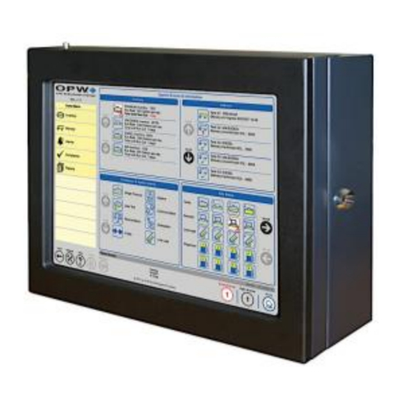
SiteSentinel
Automatic Tank Gauge System
Installation Manual
www.opwglobal.com
Central Technical Support Number:
1-877-OPW-TECH (877-679-8324)
Calls outside US and Canada:
1-708-485-4200
Hours:
Monday through Friday, 7:00 am to 6:00 pm, US CST
®
Integra 100™/500™
Fax:
1 (800) 421-3297
Document
Number: M1800, Revision 7
Issue Date:
1/15/2020
Supersedes: 5/17/2016
Advertisement
Table of Contents

Related Manuals for Dover OPW SiteSentinel Integra 100


Summary of Contents for Dover OPW SiteSentinel Integra 100
- Page 1 ® SiteSentinel Integra 100™/500™ Automatic Tank Gauge System Installation Manual www.opwglobal.com Central Technical Support Number: 1-877-OPW-TECH (877-679-8324) Document Number: M1800, Revision 7 Calls outside US and Canada: 1-708-485-4200 Fax: 1 (800) 421-3297 Issue Date: 1/15/2020 Hours: Monday through Friday, 7:00 am to 6:00 pm, US CST Supersedes: 5/17/2016...
- Page 2 2020 Delaware Capital Formation, Inc. All Rights Reserved. DOVER and the DOVER logo are registered trademarks of Delaware Capital Formation, Inc., a wholly owned subsidiary of Dover Corporation. Listings and Certifications www.opwglobal.com Doc. #: M1800, Rev. 7 Page 2 of 101...
-
Page 3: Table Of Contents
Table of Contents Applicable Warnings and Cautions ........................... 8 1.1 Technican Certifications ............................... 8 1.1.1 Installer Safety ..............................8 1.1.2 Precision Leak Test ............................9 1.1.3 Prior to Initial Inspection ............................9 1.1.4 Initial Inspection ..............................9 Integra™ ATG Console ..........................10 ®... - Page 4 4.3.1 VSmart Addressing ............................28 4.4 VSmart Capabilies ..............................29 Line Interface Module LIM (only for Integra 500) ......................30 5.1 LIM Specifications ..............................30 5.2 LIM Installation ................................30 5.3 LIM Wiring .................................. 31 5.3.1 Variable Speed Control for FE Petro ......................... 32 5.3.2 Typical FE Petro Wiring Connections ........................
- Page 5 9.5 Model 924B Probe ..............................44 9.5.1 Model 924B Specifications ..........................44 Flex Probe Installation ..............................46 10.1 Model 7100V Flex Probe (only for Integra 500) ....................... 46 10.2 Model 7100V Flex Probe Specifications ........................46 10.3 Flex Probe Installation ............................. 47 10.3.1 Flex Probe Length Determination ........................
- Page 6 Discriminating Dispenser Pan Sensor ..........................60 Discriminating Dispenser Pan Sensor Installation ......................60 Discriminating STP Sump Sensor............................61 Discriminating STP Sump Sensor Installation ......................... 61 Hydrocarbon Vapor Sensor ..............................62 Hydrocarbon Vapor Sensor Installation .......................... 62 Discriminating Interstitial Sensor ............................63 Discriminating Interstitial Sensor Installation ........................
- Page 7 Appendix H: Model 924B Installation Records ........................83 Appendix J: Flex Probe Specifications ........................... 84 Appendix K: 7100V Flex Probe Installation Records....................... 87 Appendix L: Non-Smart Sensors (only for Integra 500) ......................88 Hydrocarbon Liquid/Water Sensor ............................88 Hydrocarbon Vapor Sensor ..............................89 Hydrocarbon Vapor Sensor Installation ..........................
-
Page 8: Applicable Warnings And Cautions
1.1 Technican Certifications 1 Applicable Warnings and Cautions All installers must work with an OPW certified technician in order to ® The inside of the SiteSentinel Integra™ console contains high- ensure requirements of intrinsically safe devices are met and must voltage circuitry;... -
Page 9: Precision Leak Test
NOTE: Local codes may dictate specific installation requirements. www.opwglobal.com, and give the field wiring diagram to your installer or electrician. Installation is subject to approval by the local authority having jurisdiction at the site. 1.1.2 Precision Leak Test A third-party precision leak test should be performed on each tank and product line (especially older ones) before installing the Integra console. -
Page 10: Sitesentinel Integra™ Atg Console
2.1.1 Blank Door Unit (only for Integra 500) Integra™ ATG Console ® 2 SiteSentinel sites choosing *One (1) VSmart module can contain up to two (2) I.S. Barriers for a operate total of eight (8) barrier positions. console remote connections only, a Blank Door option with no touch screen exists. An illuminated push button will be available on the front panel for alarm notification and acknowledgement. -
Page 11: Console Specifications
2.2 Console Specifications Width: 15” (38.1 cm) Height: 12” (30.5 cm) Dimensions: 2.3 Console Installation Depth: 4” (10.0 cm) To watch the instructional video for the installation of the Integra Power: 120/240 VAC +/- 10%, 50/60 Hz, 200 W console, simply use the following QR Code. Or, the instructional video can also be found at www.YouTube.com by entering the search word... - Page 12 A = Power B = I.S. Devices C = Communication/Printer Figure 2-2 Console Knockouts (Bottom View) Figure 2-3 Console Cabinet Dimensions www.opwglobal.com Doc. #: M1800, Rev. 06 Page 12 of 101...
-
Page 13: Console Wiring
2.4.2 Wireless Connections (only for Integra 500) 2.4 Console Wiring Wireless connections can also be used for communications between For console power wiring, please refer to the appropriate field wiring the VSmart module and the console. For this type of connection, a diagram. -
Page 14: Communications Conduits
2.4.4 RS-232 Communications Conduits If a terminal or PC located more than 6 feet (1.8 m) from the console is to be connected, conduit must be installed to accommodate the RS- 232 cable. NOTE: The maximum runs for serial communication cable is 50 feet (15.24 m). -
Page 15: Wireless Petro-Net Installation With Vsmart Indoors
2.5 Wireless Petro-Net Installation with VSmart Indoors NOTE : Directional antenna may be substituted for omni-directional antenna depending upon site conditions. NOTE : It is highly recommended that all wireless Petro-Net installations are subjected to a site survey prior to installation to identify potential interference problems. -
Page 16: Petro-Net Over Ethernet Option With Vsmart
2.6 Petro-Net Over Ethernet Option with VSmart www.opwglobal.com Doc. #: M1800, Rev. 06 Page 16 of 101... - Page 17 NOTE : As an alternative to a directly connected one-to-one Ethernet connections, hubs, switches or routers may be employed. NOTE : It is very important that the subnet is used for the Integra and for the VSmarts(s) are the same. NOTE : VSmart Module is NEMA 4-rated, and may, therefore, be mounted outdoors.
-
Page 18: Field Wiring Diagram For Integra 100
2.7 Field Wiring Diagram for Integra 100 www.opwglobal.com Doc. #: M1800, Rev. 06 Page 18 of 101... - Page 19 www.opwglobal.com Doc. #: M1800, Rev. 06 Page 19 of 101...
-
Page 20: Field Wiring Diagram For Integra 500
Field Wiring Diagram for Integra 500 www.opwglobal.com Doc. #: M1800, Rev. 06 Page 20 of 101... - Page 21 www.opwglobal.com Doc. #: M1800, Rev. 06 Page 21 of 101...
-
Page 22: Console Board Inputs
2.8.1 Console Board Inputs Use the jumper settings on this page to set board inputs as desired. J1 / J2 USB Host J16 (Silence Button & Alarm Light) J21 (RS-422 & RS-485) 2x USB Host Connection Connection J4 / J7 Reserved for future expansion module Silence Button (+) RS422 ISOLATED GND... -
Page 23: Main Board Dip-Switch Configuration
2.9 Main Board DIP-Switch Configuration The photo below shows the location of the main board DIP-Switch block. The switches should all be placed in the ON position as shown. www.opwglobal.com Doc. #: M1800, Rev. 06 Page 23 of 101... -
Page 24: External Printer
Plug in the power connector of the external thermal printer. 3 External Printer To watch the instructional video for the installation of the External Printer, simply use the following QR Code. Or, the instructional video can also be found at www.YouTube.com by entering the search word “OPWGlobal”. - Page 25 Figure 3-3 Install External Thermal Printer Figure 3-5 Do Not Use This USB Port Figure 3-4 Connect Printer USB to Integra Main Board www.opwglobal.com Doc. #: M1800, Rev. 06 Page 25 of 101...
-
Page 26: Vsmart Module (Only For Integra 500)
4 VSmart Module (only for Integra 500) 4.1 VSmart Specifications Width: 11.3” (28.7 cm) Height: 5.6” (14.2 cm) Dimensions: Depth: 5.8” (14.7 cm) Standard Voltage Supply: 105 to 265 VAC, 50-60 Hz Power Consumption: 60 watts maximum Temperature Range: -40F to 158F (-40°C to 70°C) Up to two (2) I.S. -
Page 27: Vsmart Module Installation
4.2 VSmart Module Installation The VSmart module must be mounted on a wall using only the mounting tabs provided. Module knockouts and mounting dimensions are shown in drawings below. Figure 4-3 VSmart Module Dimensions 4.2.1 Probe & Sensor Conduits CAUTION: All installations must be carried out in accordance with local regulations. -
Page 28: External Vsmart Module Wiring
4.3 External VSmart Module Wiring 4.3.1 VSmart Addressing VSmart modules must be assigned a unique identification number. VSmart modules should have dedicated AC power and two (2) Module numbers must be unique within the Module Group; that is, it ground connections for the module and barrier. is possible assign the same number to both a VSmart Module and to Pull two (2) AC power wires and one (1) ground wire (14- an OM4 Module, but it is not possible to assign the same number to... -
Page 29: Vsmart Capabilies
For more information on the VSmart’s Multi-Drop Capabilities, use 4.4 VSmart Capabilies the following QR Code to watch the instructional video. Or, the instructional video can also be found at www.YouTube.com Consult the following table for capabilities of the VSmart Module in entering the search word “OPWGlobal”. -
Page 30: Line Interface Module Lim (Only For Integra 500)
5.2 LIM Installation 5 Line Interface Module LIM (only for The LIM must be mounted on a wall using only the mounting holes Integra 500) provided. Knockout locations are shown below. LIMs require communication connection to the console and AC power. The LIM is an external device that controls and monitors submersible turbine pump (STP) activities by monitoring the input/output status of NOTE: The LIM module is not NEMA-rated and must not be mounted... -
Page 31: Lim Wiring
5.3 LIM Wiring To watch the instructional video for the LIM module wiring, simply use the following QR Code. Or, the instructional video can also be found by entering the search word “OPWGlobal”. www.YouTube.com LIM modules should have dedicated AC power and two (2) ground connections for the module and barrier. -
Page 32: Variable Speed Control For Fe Petro
5.3.2 Typical FE Petro Wiring Connections 5.3.1 Variable Speed Control for FE Petro Figure 5-3 FE Petro Wiring for Variable Speed Control Figure 5-4 FE Petro Wiring Connections www.opwglobal.com Doc. #: M1800, Rev. 06 Page 32 of 101... -
Page 33: Variable Speed Control Wiring For Red Jacket
5.3.3 Variable Speed Control Wiring for Red 5.3.5 LIM Addressing Jacket LIM modules must be assigned a unique identification number. Module numbers must be unique within the Module Group; that is, it is possible assign the same number to both a LIM Module and to an OM4 Module, but it is not possible to assign the same number to more than one LIM Module or to more than one OM4 Module. -
Page 34: Om4 Module (Only For Integra 500)
NOTE: The LIM module is not NEMA-rated and must not be mounted 6 OM4 Module (only for Integra 500) with direct exposure to the elements. The OM4 for the Integra console derives its power from a 12 VAC power transformer source that is supplied with the unit. Reference the “M1801 SiteSentinel Integra™... -
Page 35: Om4 Specifications
6.2 OM4 Specifications 6.3 OM4 Wiring 6.4 OM4 Addressing Follow wiring instructions inside the module for proper Petro- CAUTION: Do not change the module number while the OM4 Net communications and power wiring instruction. module power is ON; in addition, no power can be applied to any of Connect all relay wiring to the appropriate terminal block(s). -
Page 36: Tank Alert (Overfill Alarm)
7 Tank Alert (Overfill Alarm) The Integra console has the ability to trigger an overfill alarm using the internal output relay of the OM4 module. The Tank Alert has an audible buzzer and an external light to warn the users in an event of overfill or high-product alarm. -
Page 37: Tank & Pre-Installation Preparation
Twist bare ends of wires together. 8 Tank & Pre-Installation Preparation Secure the connection with a wire nut. 8.1 Waterproof Electrical Connections CAUTION: DO NOT use electrical tape on any connections! Tape To watch the instructional video for the use of the Epoxy packs, simply prevents proper sealing of the epoxy. -
Page 38: Probe-Cable Seal-Offs
8.2 Probe-Cable Seal-Offs Seal-off the probe cables before they enter the I.S. barrier! This prevents explosive vapors from entering the I.S. barrier. Remove enough of the jacket to allow approximately 3 inches (7.6 cm) of wire leads to extend past each seal-off. DO NOT nick the wire insulation. -
Page 39: Probe Placement
8.3 Probe Placement The ideal location for a probe is in the center of the tank. The probe should be located at least 3 feet (91.4 cm) from the tank fill pipe. If this distance is less than 3 feet (91.4 cm), the force of the product entering the tank can cause the water float to rise up the shaft of the probe. -
Page 40: Probe Installation In Underground Storage Tanks
8.4 Probe Installation in Underground Storage Tanks 1. Install a manhole of at least 18 inches (45.7 cm) diameter around an unused fitting in the top of the tank. This manhole must be large enough to accommodate a weatherproof junction box. NOTE: If this fitting is not in the center of the tank, additional measurements are required for probe compensation. -
Page 41: Calculating Product Offset
8.4.1 Calculating Product Offset You can calculate product offset for a probe that is not installed in the center of a "pitched" tank. Pitch is the tilt of a tank along its horizontal axis. Some tanks are intentionally installed with one end lower than the other to allow water and sediment to collect at the low end, while clear product is drawn from the high end. -
Page 42: Rigid Probe Installation
Sensors and probes cannot be multi-dropped from the same I.S. 9 Rigid Probe Installation Channel; therefore, you must run sensors and probes to different channels on the barrier. NOTE: TLMB probes do not work with an Integra 100™ or 500™ console;... -
Page 43: Rigid Probe Specification
9.4 Rigid Probe Specification Probe Type/Float Style: Float Kits Gas: 30-1509-02 924 and 924B 2” (5.1 cm) Floats: Diesel: 30-1509-01 Gas: 30-1503-02 EECO 2” (5.1 cm) Floats: Diesel: 30-1503-01 2” (5.1 cm) product AST Flex Probes: only: 30-1503-01 AST Flex Probe 4” (10.2 cm) Water Gas: 30-0120-GAS Float Assembly for 7”... -
Page 44: Model 924B Probe
9.5.1 Model 924B Specifications 9.5 Model 924B Probe The 924B probe comes standard in stainless steel and Power Nominal 12+ VDC from I.S. Barrier can be used in a variety of liquids, including gasoline, Requirements: diesel and water. Operating -40°F to 158°F (-40°C to +70°C) The 924B Probe wiring* can be multi-dropped with up to Temperature: four (4) probes connected to the same I.S. - Page 45 Input Voltage: 23 - 28 VDC Probe Length: Minimum 12’ to 70’ in one-inch increments Enclosure Material: Kynar® Rating: IP68 0.010” (0.25 mm) Inventory Mode Resolution: +/- 0.01% of Full Scale Linearity: +/- 0.010” (0.25 mm), whichever is greater +/- 0.001% of Full Scale Repeatability: +/- 0.00025”...
-
Page 46: Flex Probe Installation
10 Flex Probe Installation 10.2 Model 7100V Flex Probe Specifications 10.1 Model 7100V Flex Probe (only for Integra 500) The 7100V Flex Probe utilizes the same magnetostrictive technology for above ground tanks up to 70 feet (15.2 m) in height. It is important to follow the handling instructions to avoid damaging the probe and voiding the warranty. -
Page 47: Flex Probe Installation
10.3.2 Flex Probe Installation Preparations 10.3 Flex Probe Installation 1. Measure the product level in the tank. Keep tank out Proper operation of the ATG system using the flex probe depends on the correct sizing of the probe. If the probe is too long, it will touch the of service to prevent product level from changing. -
Page 48: Flex Probe Determination Worksheet
10.3.3 Flex Probe Determination Worksheet www.opwglobal.com Doc. #: M1800, Rev. 06 Page 48 of 101... -
Page 49: Flex Probe Wiring
10.3.5 Installing the Flex Probe 10.3.4 Flex Probe Wiring 1. Position the coiled probe over your shoulder so that 1. Run one data cable for each probe. No splices are the coil is vertical with the float in front of you. allowed between probe junction box and console. -
Page 50: Model 327 Volumetric Line Leak Detector (Vlld) Sensor (Only For Integra 500)
11 Model 327 Volumetric Line Leak 11.1 VLLD Specifications Detector (VLLD) Sensor (only for Primary Use: Pressurized Product Lines Integra 500) OPW P/N: 30-3251 Location: Submersible Pump Leak Detector Port Alternate Location: Sensor Adaptor Fitting Detects: Product Flow Operating Temperature: -40°F to 158°F (-40°C to +70°C) Blue = Power, Brown = Signal, Black and Shield Connections:... -
Page 51: Vlld Installation
11.3 VLLD Installation To watch the instructional video for the installation of the Model 327 VLLD, simply use the following QR Code. Or, the instructional video can also be found at www.YouTube.com by entering the search word “OPWGlobal”. Figure 11-2 Remove Burrs Plug the line test port. - Page 52 Figure 11-4 Tighten Sensor www.opwglobal.com Doc. #: M1800, Rev. 06 Page 52 of 101...
-
Page 53: Vlld Wiring
11.4 VLLD Wiring Connect the sensor wires to the field wires in the junction box using the supplied wire nuts. Seal the electrical connections with the epoxy seal packs. Clean the area and power the pump. Figure 11-6 VLLD Wiring Connections Figure 11-5 VLLD Installation Diagram Overview www.opwglobal.com Doc. -
Page 54: Sensor Technology Overview
Sensor 12.3 Multi-drop Installation The Integra’s internal barrier and optional VSmart Module allows for Technology Overview the ability to multi-drop the sensors and probes. When using this The OPW smart sensors have the ability to monitor all contained installation method; follow the below directions to ensure approved areas of the fuel-storage system: tank interstice, piping sumps, STP wiring. -
Page 55: Interstitial Sensor
12.4 Interstitial Sensor Interstitial Sensors can be installed around the inside perimeter of the retaining wall or “snaked” under the length of an above ground storage tank within the retaining wall area. Interstitial Sensors can also be installed in manways, in trenches or inside a sump. -
Page 56: Wet Well Monitoring, Single-Wall Tank
12.5 Wet Well Monitoring, Single-Wall Tank In a typical wet well monitoring layout for a single-wall tank, the sensors are placed around the perimeter of the tanks. The monitoring wells are dug as close as possible to the tanks or product lines for optimal sensor response. -
Page 57: Appendix A: Opw Smart Sensors
Appendix A: OPW Smart Sensors Interstitial Level Sensor Float Switch Specifications Interstitial Level Sensor Float Switch Primary Use(s): Interstitial Area OPW P/N: 30-0231-S IntelliSense™ Board Alternate Use(s): Sumps and Dispenser Pans Detects: Liquid Operating Temperature: -40°F to 168°F (-40°C to +70°C) Length: 3.9”... -
Page 58: Single-Level Sump Sensor
Single-Level Sump Sensor OPW P/N: 30-0231-L Single-Level Sump Sensor Specifications Detects: Liquid Cable Requirements: Belden #88760 or Alpha #55371 Operating Temperature: -40°F to 158°F (-40°C to +70°C) Length: 3.75” (9.5 cm), Diameter: 2.9” Dimensions: (7.4 cm) Maximum Wiring Length*: 1,000’ (305 m) field wiring Single-Level Sump Sensor The Single-Level Sump Sensor is designed to detect the presence of liquid in sumps, dispenser pans, and other locations where the... -
Page 59: Liquid-Only Float Sensor
Liquid-Only Float Sensor OPW P/N: 30-0230-S Liquid-Only Float Sensor Primary Use(s): STP Sumps and Dispenser Pans Alternate Use(s): Use Steel Tank Interstitial Detects: Liquid Operating Temperature: °F to 158°F (-40°C to +70°C) Length: 3.5” (8.9 cm), Width: 1.43” (3.6 cm) Dimensions: Cable Requirements: Belden #88760 or Alpha #55371... -
Page 60: Discriminating Dispenser Pan Sensor
Discriminating Dispenser Pan Sensor OPW P/N: 30-0232-DH-10 Discriminating Dispenser Pan Sensor Specifications Primary Use(s): Dispenser Pan/Sump Alternate Use(s): STP Sumps Detects: Low Liquid, High Liquid, Fuel Operating Temperature: -40°F to 158°F (-40°C to +70°C) ® Belcor Length: 11.1” (28.2 cm), Diameter: 2.3” Inside Dimensions: (5.8 cm) -
Page 61: Discriminating Stp Sump Sensor
Discriminating STP Sump Sensor Discriminating STP Sump Sensor Specifications OPW P/N: 30-0232-DH-20 Primary Use(s): STP Sumps Alternate Use(s): Dispenser Pans/Sumps Detects: Low Liquid, High Liquid, Fuel Operating Temperature: -40°F to 158°F (-40°C to +70°C) Length: 21.1” (53.6 cm), Diameter: 2.3” Sensor Dimensions: (5.8 cm) ®... -
Page 62: Hydrocarbon Vapor Sensor
Hydrocarbon Vapor Sensor OPW P/N: 30-0235-V Hydrocarbon Vapor Sensor Specifications Detects: Hydrocarbon Vapors Operating Temperature: -40°F to 158°F (-40°C to +70°C) Hydrocarbon Vapor Sensor Length: 3.5” (8.9 cm), Diameter: 0.9” Dimensions: The Hydrocarbon Vapor Sensor detects hydrocarbon vapors in dry (2.3 cm) monitoring wells. -
Page 63: Discriminating Interstitial Sensor
Discriminating Interstitial Sensor Discriminating Interstitial Sensor Specifications OPW P/N: 30-0236-LW Primary Use(s): Interstitial Space Alternate Use(s): Dispenser Pans and STP Sumps Detects: Liquids (Fuel and Water) Discriminating Interstitial Sensor The Discriminating Interstitial Sensor utilizes a solid-state optical technology to detect the presence of fluid in the annular space of a Operating Temperature: -40°F to 158°F (-40°C to +70°C) tank, and conductive probes to distinguish fluid type (water or... -
Page 64: Interstitial Hydrocarbon Liquid Sensor With Water Indicator
Interstitial Hydrocarbon Liquid Sensor with Interstitial Hydrocarbon Liquid/Water Sensor Specifications Water Indicator OPW P/N: 30-0234-HW-01 Detects: Liquid hydrocarbons/water Operating Temperature: -40°F to 158°F (-40°C to +70°C) Length: 13.8” (35 cm), Width: 1.0” (2.5 cm) Dimensions: Uncontaminated: 1000-3000 ohms Nominal Resistance: Contaminated: 10,000-200,000 ohms Cable Requirements: Belden #88760 or Alpha #55371... -
Page 65: Hydrocarbon Liquid Sensor With Water Indicator
Hydrocarbon Liquid/Water Sensor Specifications Hydrocarbon Liquid Sensor with Water Primary Use(s): Monitoring wells Indicator OPW P/Ns: 6 feet: 30-0234-HW-06; 15 feet: 30-0234-HW-15; Detects: Liquid hydrocarbons and water 20 feet: 30-0234-HW-20 Operating Temperature: -40°F to 158°F (-40°C to +70°C) Length: 6’ (1.9 m), 15’ (4.6 m) or 20’ (6.1 m) Dimensions: Diameter: 0.7”... -
Page 66: Dual-Float Dispenser Sump Sensor
*NOTE: Maximum Wiring Length is the maximum length of cable to be used to connect all sensors on an Dual-Float Dispenser Sump Sensor Dual-Float Dispenser Sump Sensor Specifications OPW P/N: 30-0232-D-10 Primary Use(s): Dispenser Pan/Sump Alternate Use(s): STP Sumps Detects: Low Liquid, High Liquid, Fuel Operating Temperature: -40°F to 158°F (-40°C to +70°C) -
Page 67: Dual-Float Stp Sump Sensor
Dual-Float STP Sump Sensor Dual Float STP Sump Sensor Specifications OPW P/N: 30-0232-D-20 Primary Use(s): Dispenser Pan/Sump Alternate Use(s): STP Sumps Detects: Low Liquid, High Liquid, Fuel Operating Temperature: -40°F to 158°F (-40°C to +70°C) Length: 21.1” (28.2 cm), Diameter: 2.3” (5.8 cm) Dimensions: Low: 1.5”... -
Page 68: Dual-Float Brine Sensors
Dual Float Brine Sensor (D-10) Specifications Dual-Float Brine Sensors Primary Use(s): Measure Level of Brine solution Dual-Float Brine Sensor (D-10) OPW P/N: 30-0232-D-10B Detects: Low Liquid, High Liquid Operating Temperature: -40°F to 158°F (-40°C to +70°C) Length: 21.1” (28.2 cm), Diameter: 2.3” (5.8 cm) Dimensions: Low: 1.5”... -
Page 69: Dual-Float Brine Sensor (D-20B)
Dual-Float Brine Sensor (D-20B) Dual Float Brine Sensor (D-20B) Specifications Part No. 30-0232-D-20B Primary Use(s): Measure Level of Brine solution Detects: Low Liquid, High Liquid Operating Temperature: -40°F to 158°F (-40°C to +70°C) Length: 21.1” (28.2 cm), Diameter: 2.3” (5.8 cm) Dimensions: Low: 1.5”... -
Page 70: Universal Reservoir Sensor
Universal Reservoir Sensor Use a Universal Reservoir Sensor with hydrostatically monitored tanks. The Reservoir Sensor monitors the level of the liquid in the reservoir of a double-walled tank. The sensor has a single float that detects abnormally high or low liquid levels within the reservoir. If a leak occurs in either wall of a tank, it causes the liquid in the reservoir to rise or fall. -
Page 71: Density Measurement Sensor (Dms)
Density Measurement Sensor (DMS) Density Measurement Sensor OPW P/N: 30-3232 Nitrophyl, Delrin, and Stainless-Steel Materials: spring Resolution: 0.00004 g/cc Accuracy: +/- 0.0025 g/cc 0.6 – 1.0 g/cc Density Range: Operating -40°F to 158°F (-40°C to +70°C) Temperature: Length: 11” (27.9 cm), Diameter: 2” (5.1 Dimensions: Sensors per Barrier: 16 maximum... -
Page 72: Dms Installation
Density Sensor. The suggested level is 17 inches DMS Installation (43.2 cm) or higher. NOTE: As density sensing is no longer an option in the system, the 2. Measure the distance between the end of the probe sensor itself will be picked up by the system once the device is shaft and top end of the Density Sensor. -
Page 73: Appendix B: Existing Opw/Eeco Equipment
Appendix B: Existing OPW/EECO 924A Probe Specifications Equipment Operating Temperature: -40°F to 158°F (-40°C to +70°C) Model 924A Probes ≈ 2.2” (5.6 cm) x 7.5” (19.1 cm) Head Dimensions: CAUTION: CANNOT BE MULTI-DROPPED ON 6’ (1.8 m), gas/oil-resistant cable Required Cable: VSMART. -
Page 74: Model Eeco Probes
EECO Probes Model EECO Probes Probe Type: Magnetostrictive with Floats CAUTION: CANNOT BE MULTI-DROPPED ON VSMART. Probe Length: From 4’ to 16’, in 6-inch increments The Model EECO Probe is primarily used in Material: Stainless Steel Shaft underground storage tanks for inventory and leak detection. -
Page 75: Appendix C: Smart Module (Only For Integra 500)
Smart Module Specifications Appendix C: Smart Module (only for Electrical Requirements Integra 500) Standard Voltage Supply: 105 to 125 VAC, 60 Hz Optional Voltage Supply: 220 to 240 VAC, 50 Hz Power Consumption: 60 W maximum Power Supply Module Board 17”... -
Page 76: Appendix D: Maintenance Kit
Appendix D: Maintenance Kit OPW P/N: 20-4407 The Hardware Maintenance Kit includes a USB key and a USB mouse. The two (2) USB devices can be plugged into either of the external USB ports on the left-hand side of the console. The two devices can be used in the event of system failure or when retrieving key troubleshooting files. -
Page 77: Appendix E: Model 924B Probe Part Numbers
Appendix E: Model 924B Probe Part Numbers Model 924B Probe Part Numbers Probe Length Length (cm) Part Number 53” Probe for 4’ (122 cm) Diameter/Height Tank 134.6 cm 30-B053 69” Probe for 5’ (152 cm) Diameter/Height Double-Wall Tank 175.3 cm 30-B069 77”... -
Page 78: Appendix F: Output Relay Installation Report
Appendix F: Output Relay Installation Report Output Location: Output Controls: Normally Open/Normally Closed Internal/External OM4, LIM External Alarm, Dispenser etc. Integra Internal Relay Output 1 OM4 1 Position 1 OM4 1 Position 2 OM4 1 Position 3 OM4 1 Position 4 OM4 2 Position 1 OM4 2 Position 2 OM4 2 Position 3... - Page 79 OM4 3 Position 4 OM4 4 Position 1 OM4 4 Position 2 OM4 4 Position 3 OM4 4 Position 4 LIM 1 Position 1 LIM 2 Position 1 LIM 3 Position 1 LIM 4 Position 1 www.opwglobal.com Doc. #: M1800, Rev. 06 Page 79 of 101...
-
Page 80: Appendix G: Sensor Labels
Appendix G: Sensor Labels Installed Sensor Labels Description (Location, e.g., Sump, Sensor #, etc.) Place Label Here Place Label Here www.opwglobal.com Doc. #: M1800, Rev. 06 Page 80 of 101... - Page 81 Installed Sensor Labels Description (Location, e.g., Sump, Sensor #, etc.) Place Label Here Place Label Here www.opwglobal.com Doc. #: M1800, Rev. 06 Page 81 of 101...
- Page 82 Internal Barrier or VSmart Barrier Position (1-4) (Number in chain, if Probe Serial Number Tank Number Product in Tank Barrier # applicable, 1-4) www.opwglobal.com Doc. #: M1800, Rev. 06 Page 82 of 101...
-
Page 83: Appendix H: Model 924B Installation Records
Appendix H: Model 924B Installation Records www.opwglobal.com Doc. #: M1800, Rev. 06 Page 83 of 101... -
Page 84: Appendix J: Flex Probe Specifications
Appendix J: Flex Probe Specifications Multiple RTD Thermistor Location Dead Zone Probe Type Overall Probe Length Thermistor Location Overall Length Dead Band Clearance Shorter than 144” (366 cm) (Temp Span +7” (17.9 cm))/6 51”-144” (130-366 cm) 6” (15.2 cm) 1” (2.5 cm) 7100V (R5) 145”- 288”... - Page 85 433”- 600” (1,100 -1,524 cm) 38” (96.5 cm) 7100V (R1 & T1) Flex Probe Catalog Number (Example: 7100V030R1XF1L049) 7100 Model Number Flexible PVDF Tube w/Male NPT PVDF Connector & 2’ (61 cm) Teflon® Cable Temperature Span (in) Number of Thermistors Standard Number of Floats www.opwglobal.com...
- Page 86 L048 Overall Length www.opwglobal.com Doc. #: M1800, Rev. 06 Page 86 of 101...
-
Page 87: Appendix K: 7100V Flex Probe Installation Records
Appendix K: 7100V Flex Probe Installation Records Internal Barrier or VSmart Probe Serial Number Probe Part Number (Catalog #) Tank # Product in Tank Barrier Position 0–3 Barrier # www.opwglobal.com Doc. #: M1800, Rev. 06 Page 87 of 101... -
Page 88: Appendix L: Non-Smart Sensors (Only For Integra 500)
Appendix L: Non-Smart Sensors (only for Integra 500) Hydrocarbon Liquid/Water Sensor OPW P/N: 30-3210-nn Hydrocarbon Liquid/Water Sensor The hydrocarbon liquid/water sensor is used primarily in monitoring wells with fluctuating groundwater tables, or in the containment areas of tanks, pumps and pipes. The sensor contains a carbon/polymer material that changes its resistance when exposed to liquid hydrocarbons, as well as a water sensor that relies on the conductivity of water to detect its presence,... -
Page 89: Hydrocarbon Vapor Sensor
Hydrocarbon Liquid/Water Sensor *NOTE: Maximum Wiring Length is the maximum length of cable to be used to connect all sensors on an individual channel. This length Typical Uses: Monitoring Wells includes run of cable from I.S. Barrier to each sensor board in the string. - Page 90 *NOTE: Maximum Wiring Length is the maximum length of cable to be used to connect all sensors on an individual channel. This length includes run of cable from I.S. Barrier to each sensor board in the string. www.opwglobal.com Doc. #: M1800, Rev. 06 Page 90 of 101...
-
Page 91: Combo Single-Level / Hydrocarbon Liquid Sump Sensor
Combo Single-Level / Hydrocarbon Liquid Sump Sensor Combo Single Level/Hydrocarbon Liquid Sump Sensor OPW P/N: 30-3224 Substances Detected: Liquid Hydrocarbon and Water Operating Temperature: -4°F to 122°F (-20°C to +50°C) Dimensions: 1.3” x 3.9” (3.4 cm x 10 cm) 30-3221-1A 1.7”... -
Page 92: Combo Dual-Level/Hydrocarbon Liquid Sump Sensor
Combo Dual-Level/Hydrocarbon Liquid Sump Combo Dual Level/Hydrocarbon Liquid Sump Sensor Sensor OPW P/N: 30-3225 Substances Detected: Liquid Hydrocarbon and Water Operating Temperature: -4°F to 122°F (-20°C to +50°C) Dimensions: 2.4” x 14” (6 cm x 35.6 cm) 30-3221-2 1.7” x 13.2” (4.4 cm x 33.5 cm) 30-3219-12 Required Cable: 12’... - Page 93 *NOTE: Maximum Wiring Length is the maximum length of cable to be used to connect all sensors on an individual channel. This length includes run of cable from I.S. Barrier to each sensor board in the string. www.opwglobal.com Doc. #: M1800, Rev. 06 Page 93 of 101...
-
Page 94: Single-Level Sump Sensor
Single-Level Sump Sensor Single Level Sump Sensor OPW P/N: 30-3221-1 Substance Detected: Liquid Operating Temperature: -4°F to 122°F (-20°C to +50°C) 2.9” x 3.7” (7.4 cm x 9.5 cm) Dimensions: 15’ (4.6 m) of gas-and-oil resistant cable Required Cable: Maximum Wiring Length*: 1,000’... -
Page 95: Dual-Level Reservoir Sensor
Dual-Level Reservoir Sensor Dual Level Reservoir Sensor Part # 30-3221-2 Substance Detected: Liquid Operating Temperature: -4°F to 122°F (-20°C to +50°C) 2.4” x 14” (6 cm x 35.6 cm) Dimensions: 15’ (4.6 m) gas-and-oil resistant cable Required Cable: Maximum Wiring Length*: 1,000’... -
Page 96: Hydrocarbon Liquid Sump Sensor
Hydrocarbon Liquid Sump Sensor Hydrocarbon Liquid Sump Sensor Part #30-3219-12 Substance Detected: Liquid Hydrocarbon Operating Temperature: -4°F to 122°F (-20°C to +50°C) 1.7” x 31.2” (4.4 cm x 33.5 cm) Dimensions: 12’ (3.6 m) gas-and-oil resistant cable Required Cable: Maximum Wiring Length: 1000’... - Page 97 *NOTE: Maximum Wiring Length is the maximum length of cable to be used to connect all sensors on an individual channel. This length includes run of cable from I.S. Barrier to each sensor board in the string. www.opwglobal.com Doc. #: M1800, Rev. 06 Page 97 of 101...
-
Page 98: Interstitial Optical Liquid Sensor
Interstitial Optical Liquid Sensor Interstitial Optical Liquid Sensor Part #30-3223 Substance Detected: Liquid Operating Temperature: -4°F to 122°F (-20°C to +50°C) 0.7” x 2.8” (1.8 cm x 7 cm) Dimensions: 20’ (6 m) gas-and-oil resistant cable Required Cable: 1,000’ (305 m) Maximum Wiring Length*: Interstitial Optical Liquid Sensor Multi-Drop Restriction:... -
Page 99: Appendix M: Declaration Of Conformity
Appendix M: Declaration of Conformity www.opwglobal.com Doc. #: M1800, Rev. 06 Page 99 of 101... - Page 100 www.opwglobal.com Doc. #: M1800, Rev. 06 Page 100 of 101...
-
Page 101: Index
Index IntelliSense™................25, 47 Adapter Collar & Riser Cap .............38 Alpha 55371 ..................39 Interstitial Hydrocarbon Liquid with ..........65 Belcor ..................59, 60 Interstitial Level Sensor-Float Switch..........50 Belden 88760 ........39, 56, 57, 58, 59, 60, 61, 62, 79 Interstitial Sensor ................48 Belden 88761 ..................39 Model 7100V Flex Probes ..............
Need help?
Do you have a question about the OPW SiteSentinel Integra 100 and is the answer not in the manual?
Questions and answers