Dover markem-imaje 5200 Installation And Setup Manual
Hide thumbs
Also See for markem-imaje 5200:
- Operation manual (67 pages) ,
- Instruction manual (37 pages) ,
- Service manual (200 pages)
Table of Contents
Advertisement
Quick Links
Advertisement
Table of Contents
Troubleshooting

Related Manuals for Dover markem-imaje 5200


Summary of Contents for Dover markem-imaje 5200
- Page 1 i n s t a l l a t i o n a n d s e t u p g u i d e...
- Page 3 To the best of our knowledge, the information contained in this guide was correct at the time of publication. However, continual enhancement of our products can result in some differences between the instructions represented in this guide and your coder. MARKEM, Touch Dry, and CimControl are registered trademarks of MARKEM Corporation.
-
Page 5: Table Of Contents
TABLE OF CONTENTS SECTION 1 General Information ....... . 1 1.0 Welcome to the Model 5200/5400 . - Page 6 TABLE OF CONTENTS 3.2 Installing an External Encoder ........42 3.3 Installing the Serial Interface.
- Page 7 TABLE OF CONTENTS 4.13 Auto Purge..........68 4.13.1 Auto Purge Time .
- Page 8 TABLE OF CONTENTS 8.15.5 Verify Both ..........79 8.15.6 Reader Port Settings .
- Page 9 TABLE OF CONTENTS 13.3 Shift ID ........... . 99 13.4 Start Time .
- Page 10 TABLE OF CONTENTS SECTION 4 Database Management......111 1.0 The Database Management Menu........113 2.0 Retrieve Files .
-
Page 11: Section 1 General Information
SECTION 1 General Information Model 5200/5400 Installation and Setup Guide... -
Page 13: General Information Section
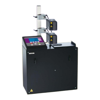
GENERAL INFORMATION SECTION 1 1.0 Welcome to the Model 5200/5400 The Model 5200 and 5400 are part of the 5000 Series of case coders, which use MARKEM Touch Dry® ink technology, and provide flexibility and quality in coding cases directly on your packaging line. -
Page 14: Related Documentation
GENERAL INFORMATION SECTION 1 printheads that can be configured, and design changes necessary to accommodate the printheads. Most procedures and pictures throughout this guide depict the Model 5200. Adapt the instructions as needed for the Model 5400. 1.2 Related Documentation •... -
Page 15: Specifications
GENERAL INFORMATION SECTION 1 2.0 Specifications Weight: Print station (not including umbilical lines) Model 5200: Approx. 63kg (140 lb) Model 5400: Approx. 77kg (170 lb) Printhead: Approx. 2.1kg (4.6 lb) Dimensions: See Dimensional Drawing (Paragraph 3.0) Noise Emission: Does not exceed 75 dB(A) Electrical Standards: CE marked ETL listed, conforms to ANSI/UL 60950 and... -
Page 16: Dimensional Drawing
GENERAL INFORMATION SECTION 1 3.0 Dimensional Drawing INCHES 43.6 25.5 57.8 21.7 21.7 11.2 12.2 15.8 48.3 64.8 146.85 55.1 55.1 0855848enh 6/08... -
Page 17: Safety Information
GENERAL INFORMATION SECTION 1 4.0 Safety Information The Model 5200/5400 has been designed to meet various safety standards. To alert you to potentially hazardous situations, labels and messages appear on the coder and throughout the guides. CAUTION refers to a potentially hazardous situation which, if not avoided, could result in personal injury. -
Page 18: Automatic Startup
GENERAL INFORMATION SECTION 1 4.2 Automatic Startup CAUTION Do not allow an automatic packaging machine startup after a Model 5200/5400 reset. Install the Model 5200/5400 Fault Relay output for a manual packaging machine reset. Automatic startup of a packaging machine could kill or seriously maim an operator. TECHNICAL ISSUE: The Model 5200/5400 has an optional feature which enables it to stop or prevent packaging machine operation when coder conditions prevent marking the packages. -
Page 19: Safety Labels
GENERAL INFORMATION SECTION 1 4.3 Safety Labels High Voltage To prevent injury from electrical shock, remove the power cord from the electrical outlet before performing troubleshooting or repair. Electronic troubleshooting must be performed by personnel trained to troubleshoot electrical circuits. Hot Surfaces To prevent injury from burns, be careful not to touch the jet array surface or hot ink directly. - Page 20 GENERAL INFORMATION SECTION 1 FRONT REAR 0855848enh 6/08...
-
Page 21: Foreseen Use
GENERAL INFORMATION SECTION 1 4.5 Foreseen Use The Model 5200/5400 is designed as an industrial case coder, intended for printing on corrugated containers. This coder was designed for or adapted by Markem-Imaje to a specific application at the time of sale. This application is the intended use. -
Page 22: Label And Symbol Identification
GENERAL INFORMATION SECTION 1 5.0 Label and Symbol Identification Serial/I.D./Rating Label This label is located on the rear of the enclosure and indicates the following: Model number Information about the coder Information about Markem-Imaje Patents covered Serial number CE mark Electrical specifications Attention symbol Electrical diagram number... - Page 23 GENERAL INFORMATION SECTION 1 CE Mark This symbol indicates that the coder meets safety and environmental requirements as defined in the European Directives. ETL Listed This label indicates that the coder conforms to ANSI/UL Standard 60950 and is certified to Canada/CSA C22.2 Standard 60950. Status This symbol is located near the STATUS LED on the user interface module, and indicates whether or not the coder is ready to print.
- Page 24 GENERAL INFORMATION SECTION 1 Optional Control Unit (OCU) This symbol indicates the interface device port that is used for bar code readers or a product ID reader. Serial Port This symbol indicates the serial ports. I0I0I (1) - Host (RS232, RS422, and RS485) I0I0I (2) - ASCII Comms (RS232) I0I0I (3) - Not Used (RS232) Printhead...
-
Page 25: Removal From Service
GENERAL INFORMATION SECTION 1 6.0 Removal from Service Follow these instructions to remove the coder from service. These instructions also pertain to transporting or storing the coder. Use the Shutdown menu to cool down and power off the coder. Disconnect the AC power cord from the electrical source. Disconnect cables and connections, accessed from the I/O door. -
Page 27: Section 2 Installation
SECTION 2 Installation Model 5200/5400 Installation and Setup Guide... -
Page 29: Installation Section
INSTALLATION SECTION 2 1.0 Machine Requirements The coder includes: • the enclosure with user interface module • up to two printheads (Model 5200) up to four printheads (Model 5400) • umbilical lines • options, such as a product sensor, encoder, or serial interface This equipment must be installed in accordance with applicable requirements. -
Page 30: Printing Limitation
INSTALLATION SECTION 2 1.4 Printing Limitation If the image to be printed contains any dynamic data, the Model 5200/5400 should not be used to print images onto cartons on two independent packaging lines, as it is likely that incorrectly updated images will be printed and a continuous fault condition will occur. -
Page 31: Installing The Enclosure
INSTALLATION SECTION 2 2.1 Installing the Enclosure The enclosure is available in two possible configurations, and is determined at the time of sale. • The Model 5200 enclosure accommodates up to two printheads. There is one transformer, one printhead volt board, and one VPC to accommodate printhead 1 and printhead 2. -
Page 32: Ac Power Cord And Plug
INSTALLATION SECTION 2 The coder is shipped in the 230V configuration. To use the coder in the 230V configuration, no change is needed. To change the voltage configuration, follow the instructions in “Changing the Voltage Configuration” below. 2.1.1 AC Power Cord and Plug Markem-Imaje does not supply an AC power plug for the coder due to the numerous plug configurations. -
Page 33: Changing The Voltage Configuration
INSTALLATION SECTION 2 2.1.2 Changing the Voltage Configuration The Model 5200 coder can be configured for 115V, 200V, 208V, or 230V by moving the left-hand wire (1, Figure 2) on the soft start board, located inside the enclosure. The Model 5400 coder can be configured for 200V, 208V, or 230V by moving the left-hand wire (1, Figure 3) on the soft start board, located inside the enclosure. - Page 34 INSTALLATION SECTION 2 Using a Phillips head screwdriver, loosen the retaining screw enough to pull down the left-hand wire. Move the wire to the appropriate position using the label below the soft start board for reference. Tighten both retaining screws (Figure 2 and 3).
- Page 35 INSTALLATION SECTION 2 Figure 5 10. Place the remaining spare labels at the base of the enclosure for storage. 11. If the transformer electrical connector(s) were disconnected, reconnect them. Note that the transformer electrical connectors are interchangeable, and either connector can go into either socket.
-
Page 36: Installing The Printhead
INSTALLATION SECTION 2 2.2 Installing the Printhead Up to four printheads can be used, depending on your configuration. The printheads are called printhead 1 (PH1), printhead 2 (PH2), printhead 3 (PH3), and printhead 4 (PH4) in the manuals and in the software. - Page 37 INSTALLATION SECTION 2 Set the vertical bar into the vertical mount and tighten the vertical mount wedge. Assemble the vertical mount wedge into the vertical mount, leaving the screws loose. Install the leveling feet (1, Figure 7) or casters (2, Figure 7). If equipped with casters, lock them in place.
-
Page 38: Assembling The Mounting Pole
INSTALLATION SECTION 2 2.2.2 Assembling the Mounting Pole If using the printhead vertical mounting pole (Figure 8), use the holes provided to mount to your packaging line. Assemble the printhead mounting bar to the vertical mounting pole. Use the applicable figure as a guide for assembling the printhead mounting bar. -
Page 39: Mounting The Printhead
INSTALLATION SECTION 2 2.2.3 Mounting the Printhead Depending on the enclosure ordered, the coder supports up to four printheads, which can be configured to print independently. The printheads must be positioned within 3m (10') of the enclosure. Each printhead must be mounted to a bracket that is aligned with the packaging line. - Page 40 INSTALLATION SECTION 2 Vertical Jetting Horizontal Jetting Down Jetting 45° Slant Tilt Rotation Figure 10 Mechanical shock or vibration to the printhead can cause upper jet dropout. The best way to prevent this is to isolate mechanical forces from the printhead during installation. If this is not possible, jet dropout problems may be prevented by using the Custom Vacuum parameter to decrease the low vacuum settings.
- Page 41 INSTALLATION SECTION 2 NOTE: Rotating or tilting a printhead outside the indicated ranges will result in ink being trapped in the low vacuum system, which will result in printhead failure. Slide the printhead onto the printhead mounting bar (1, Figure 11) and tighten the printhead wedge screw (2, Figure 11) to secure it.
-
Page 42: Down Jetting Mounting Position
INSTALLATION SECTION 2 2.2.4 Down Jetting Mounting Position For the down jetting mounting position, the printhead horizontal mount assembly (P/N 0828201) and the printhead mounting bar assembly (P/N 0828517) must be ordered. Disassemble both blocks from the printhead horizontal mount assembly. -
Page 43: Software Parameters For The Printhead Jetting Position
INSTALLATION SECTION 2 2.2.5 Software Parameters for the Printhead Jetting Position Later in the installation procedure software parameters may need to be set for each printhead mounted. The physical mounting position determines the appropriate low vacuum settings. Do not power on the coder or change the software parameters until installation is complete. -
Page 44: Connecting Umbilical Lines
INSTALLATION SECTION 2 2.3 Connecting Umbilical Lines For each printhead installed, the ink line, electrical line, and vacuum line must be connected to the enclosure and the printhead. 2.3.1 Connecting the Ink Line Inside the Enclosure CAUTION. High Voltage. The AC power must be disconnected. Failure to do so can result in death or serious injury from an electrical shock. - Page 45 INSTALLATION SECTION 2 Figure 15 Determine which fitting(s) will be used. As a convention, it is recommended that the fittings be used for printheads 1 to 4, from top to bottom as shown in Figure 16 (Model 5200 is shown). Figure 16 0855848enh 6/08...
- Page 46 INSTALLATION SECTION 2 The aluminum ink plug and slotted stainless steel nut must be removed for each ink line that will be used. To remove the aluminum ink plug and slotted stainless steel nut, place a 1/2” open-end wrench on the ink line nut and rotate it counterclockwise, while holding a larger nut with a 5/8”...
- Page 47 INSTALLATION SECTION 2 Figure 18 Figure 19 11. Remove the duct cover (1, Figure 20). Route the electrical connector through the wire duct (2, Figure 20) and connect it to the printhead volt board. The electrical connectors must be connected as follows: PH1 to P3 on the left-hand printhead volt board (PH1, Figure 21) PH2 to P2 on the left-hand printhead volt board (PH2, Figure 21) PH3 to P3 on the right-hand printhead volt board (PH3, Figure 21)
-
Page 48: Connecting Vacuum And Electrical Lines To The I/O Panel
INSTALLATION SECTION 2 2.3.2 Connecting Vacuum and Electrical Lines to the I/O Panel Locate the I/O door on the rear of the enclosure. Loosen the screw and open the I/O door. Connect the low vacuum line (gray) to the low vacuum connection (1, FIgure 22) and the high vacuum line (red) to the high vacuum connection (2, Figure 22). -
Page 49: Connecting Umbilical Lines To The Printhead
INSTALLATION SECTION 2 2.3.3 Connecting Umbilical Lines to the Printhead Determine which umbilical lines to connect to printhead 1, printhead 2, printhead 3, and printhead 4. Connect the ink line nut using the plastic knob provided (1, Figure 24) to printhead 1. Be careful not to crossthread the nut. NOTE: Ensure that the ink line is raised off the floor to protect against incidental damage and to prevent the cold floor from forming cold spots. -
Page 50: Installing Options
INSTALLATION SECTION 2 3.0 Installing Options Depending upon options and accessories ordered, additional components may need to be installed. 3.1 Installing a Product Sensor A product sensor can be installed in applications where fixed spacing is not suitable. Product sensors are mounted upstream of the printhead and can be adjusted to send the signal upon detecting the leading edge or trailing edge of the carton. - Page 51 INSTALLATION SECTION 2 If not using the printhead mounting, make sure the carton will clear the product sensor and the jet array. Minimize excessive movement or vibration. Ideally, the product sensor should be mounted approximately 2,5cm (1.0 inch) from the product being sensed.
-
Page 52: Installing An External Encoder
INSTALLATION SECTION 2 3.2 Installing an External Encoder An external encoder should be used when the conveyor belt speed is inconsistent or when printing bar codes. One encoder should be used for each conveyor segment and printhead configuration. Encoder 1 or Encoder 2 will later need to be selected for the Encoder Settings parameter in the Printhead Settings Menu. -
Page 53: Installing The Serial Interface
INSTALLATION SECTION 2 3.3 Installing the Serial Interface A serial interface may be used to interface the Model 5200/5400 with a host computer or other device. Three serial ports located on the I/O panel are labeled as follows. 1 = Host (RS232, RS422, and RS485) 2 = ASCII Comms (RS232) 3 = Not Used (RS232) Port 1 Pin-out... -
Page 54: Ethernet Host Port Setup
INSTALLATION SECTION 2 3.4 Ethernet Host Port Setup The Model 5200/5400 can communicate with a host computer via an Ethernet link. After connecting the Ethernet cable from the Model 5200/5400 to the host computer, Ethernet settings must be established in the software. Locate the I/O door on the rear of the enclosure. -
Page 55: Installing The Signal Tower
INSTALLATION SECTION 2 3.5 Installing the Signal Tower The three-color lamps on the optional signal tower mimic the LED indicators on the user interface module. • Green Status • Blue • Amber Fault Mount the signal tower to the rear of the enclosure, using the tapped holes. -
Page 56: Installing The Keyboard
INSTALLATION SECTION 2 3.6 Installing the Keyboard An optional keyboard may be used to enter alphanumeric characters and navigate through menus. Refer to the Model 5200/5400 Operation Guide for information about keyboard functions. Obtain a keyboard with a PS2 connector. Place the keyboard in a location that is near the user interface display and accessible to the user. - Page 57 INSTALLATION SECTION 2 Busy Relay The busy relay is controlled by ASCII commands from a PLC and energizes when PLC communication is available to be addressed. To use the busy relay feature, contact your Markem-Imaje representative and ask to consult with Engineering. Normally Closed Common...
-
Page 58: Optional Control Unit (Ocu)
INSTALLATION SECTION 2 3.8 Optional Control Unit (OCU) The OCU provides the capability to interface a Model 5200/5400 coder to a verification bar code reader or Product I.D. bar code reader. Each coder can accommodate up to two verification readers and one Product ID (Traded Unit Lookup) reader. - Page 59 INSTALLATION SECTION 2 Using Figure 30 for guidance, connect the cables as follows, routing them through the slot of the foam block. • Product I.D. Reader cable: from Product I.D. Reader to the connector labeled “PRODUCT I.D.” on the OCU. •...
-
Page 60: After Installation
INSTALLATION SECTION 2 4.0 After Installation After installing the printhead, umbilical lines, electrical connections, and options, a few more tasks need to be completed before powering on the coder. With the front cover removed, locate the spare labels at the base of the enclosure (Figure 30). -
Page 61: Getting Started
INSTALLATION SECTION 2 5.0 Getting Started 5.1 Connecting the AC Power This procedure assumes that: • All mechanical and electrical components have been installed as explained in the preceding paragraphs. • The front cover of the enclosure is installed. • The I/O door is closed. -
Page 62: Setting Software Parameters
INSTALLATION SECTION 2 5.3 Setting Software Parameters Before attempting to print, it is necessary to set software parameters. For many parameters, the default settings will produce successful results. For some parameters, the settings must be customized for your application. If options such as an encoder or serial interface are installed, the appropriate parameters must be set. -
Page 63: Recording Your Setup Parameters
INSTALLATION SECTION 2 Machine Setup Custom Codes... Shift Codes... SSCC Settings... Date Change... Image Settings... Error Conditions... Initialization... Page Page Down The Model 5200/5400 is shipped with the menus displaying in English. A software file is available so that menus will display in other languages. -
Page 65: Section 3 Machine Setup Menu
SECTION 3 Machine Setup Menu Model 5200/5400 Installation and Setup Guide... -
Page 67: Software Introduction
MACHINE SETUP MENU SECTION 3 1.0 Software Introduction Before attempting to print, machine setup parameters must be set. Parameters are accessed from the Machine Setup menu. Refer to the Model 5200/5400 Menu Tree Diagram for a listing of machine setup parameters. The options available for each parameter depend on the access level entered. -
Page 68: Displaying The Machine Setup Menu
MACHINE SETUP MENU SECTION 3 1.2 Displaying the Machine Setup Menu Power on the coder. From the Top Level menu, press Main Menu (F4) . From the Main Menu, press Machine Setup (F4) . If required, enter a password. The Machine Setup menu will appear. Not all the Machine Setup parameters can be displayed at one time. -
Page 69: Access Level
MACHINE SETUP MENU SECTION 3 2.0 Access Level Parameter Options: None, Level 1, 2, 3 Access to various menus and functions is protected by passwords. The Access Level parameter is used to temporarily change the access level from the default to a different level. To temporarily change the access level, press F1 (Modify) when the Access Level parameter is selected. -
Page 70: User Interface
MACHINE SETUP MENU SECTION 3 3.0 User Interface Access Level: Read–1; Write–1 The User Interface menu is used to set the units, language, key beeper, LCD contrast, and clock settings. These settings are typically addressed during initial installation of the coder. To select the desired parameter, use the Down-Arrow or Up-Arrow keys. -
Page 71: Language
MACHINE SETUP MENU SECTION 3 3.2 Language Parameter Options: English (default), up to two additional languages can be downloaded Access Level: Read–1; Write–1 The Language parameter determines the language in which menus will be displayed on the User Interface Module. To display the desired option, press F1 (+) or F2 (-) when the Language parameter is selected. -
Page 72: Clock Settings
MACHINE SETUP MENU SECTION 3 3.5 Clock Settings Access Level: 1 The Clock parameter is used to set the current time and date on the internal clock. To open the Change Clock Settings dialog box, press F1 (Modify) when the Clock parameter is selected. User Interface Settings Access Level : Level 3... -
Page 73: Printhead Settings
MACHINE SETUP MENU SECTION 3 4.0 Printhead Settings The Printhead Settings menu is used to control features such as encoder settings, the print trigger, location of the printed image, image density, vacuum settings, and temperature settings. A Printhead Settings menu is available for each printhead that is connected: printhead 1, printhead 2, printhead 3, and printhead 4. -
Page 74: Fixed Space Mode
MACHINE SETUP MENU SECTION 3 4.2 Fixed Space Mode Parameter Options: Off (default), On Access Level: Read–1; Write–1 When Fixed Space Mode is On , the printhead will print continuously at the user-set internal encoder interval and the parameters available on the Printhead Settings Menu will change. The Fixed Space Standby parameter will appear directly below Fixed Space Mode;... -
Page 75: Print Trigger
MACHINE SETUP MENU SECTION 3 4.5 Print Trigger Parameter Options: Product Sensor1 (default), Product Sensor2, Disable Access Level: Read–1; Write–1 The Print Trigger parameter only appears when the Fixed Space Mode is Off . When the product passes by a sensor, the sensor generates a print trigger which signals the printhead to begin printing. -
Page 76: Mirror Image
MACHINE SETUP MENU SECTION 3 4.8 Mirror Image Parameter Options: Off (default = 3), On Access Level: Read–1; Write–1 When the Mirror Image parameter is set to On , the printed image will be a mirror image. This parameter is useful for printing on the reverse side of plastic wrap where the image will appear correctly from outside the plastic wrap. -
Page 77: Ph Orientation
MACHINE SETUP MENU SECTION 3 4.11 PH Orientation Parameter Options: Vertical (default), Horizontal, Down, Custom 1, Custom 2, Custom 3, Custom 4 - Slant Head Access Level: 2 The PH Orientation parameter allows the user to select a software option to match the physical mounting of each printhead. This parameter determines the appropriate low vacuum settings. -
Page 78: Purge Time
MACHINE SETUP MENU SECTION 3 4.12 Purge Time Parameter Options: 0.02–10.00 sec. (default = 1.8) in increments of 0.01 Access Level: Read–3; Write–4 The Purge Time parameter sets the duration of the purge in seconds, and can only be changed by Markem-Imaje service personnel. -
Page 79: Auto Purge Frequency
MACHINE SETUP MENU SECTION 3 4.13.2 Auto Purge Frequency Parameter Options: 0–50000 (default = 0); in increments of 1 Access Level: Read–3; Write–3 The Auto Purge Frequency parameter is used to specify the number of cartons that will be printed between automatic purges. A setting of 0 disables the automatic purge feature. -
Page 80: Ils Set Point
MACHINE SETUP MENU SECTION 3 5.2 ILS Set Point Parameter Options: 0–15 volts (default = 4.0) in increments of 0.1 Access Level: Read–3; Write–4 The ILS Set Point parameter is used to set the ink level sensor threshold in the printhead reservoir, measured in volts, at which the sensor detects that the coder will indicate that the ink is low. -
Page 81: Printhead Voltage
MACHINE SETUP MENU SECTION 3 5.6 Printhead Voltage Parameter Options: 115–195 (default = 115) in increments of 1 Access Level: Read–3; Write–4 The Printhead Voltage parameter is used to set the required drive voltage for the piezoelectric transducers (PZT) which jet the ink, and can only be changed by Markem-Imaje service personnel. -
Page 82: Custom Vacuum
MACHINE SETUP MENU SECTION 3 6.4 Custom Vacuum Parameter Options: 0.00–5.00 In. H 0 (default = 1.00) Access Level: Read–3; Write–3 The Custom Vacuum parameter is used to set the low vacuum setting of a printhead with a customized mounting such as rotation or tilt. -
Page 83: Printhead Mapping
MACHINE SETUP MENU SECTION 3 7.0 Printhead Mapping Parameter Options: Printhead 1, Printhead 2, Printhead 3, Printhead 4 (only available for printheads installed) Access Level: Read–1; Write–1 The Printhead Mapping Menu allows the user to designate the identity of the printheads between the Model 5200/5400 and Composer software. -
Page 84: Melt Chamber Temp
MACHINE SETUP MENU SECTION 3 8.1 Melt Chamber Temp Parameter Options: 0–140°C (default = 125° when melting and 58°C when idle) in 0.5° increments Access Level: Read–3; Write–4 The Melt Chamber Temp parameter is used to set the temperature of the ink melting chamber, and can only be changed by Markem- Imaje service personnel. -
Page 85: Slanted Printhead
MACHINE SETUP MENU SECTION 3 8.5 Slanted Printheads Parameter Options: Yes, No (default) Access Level: Read–3; Write–3 To enable the Slanted Printhead parameter, select Yes , which will set the printhead orientation to Custom 4 - Slant PH and will configure the vacuum settings properly to accommodate the 45°... -
Page 86: Remote Purge
MACHINE SETUP MENU SECTION 3 8.9 Remote Purge Parameter Options: Yes, No (default) Access Level: Read–3; Write–4 The Remote Purge parameter is used to initiate a purge remotely using Carton Sensor4 input as a prompt and can only be changed by Markem-Imaje service personnel. -
Page 87: Product Sensor Settings
MACHINE SETUP MENU SECTION 3 8.13 Product Sensor Settings The Product Sensor Settings parameters are used to designate the debounce value and the trigger type for Sensor 1 and Sensor 2. 8.13.1 Sensor Debounce Parameter Options: 0–10mm (default = 5mm) in increments of 1mm Access Level: Read–3;... -
Page 88: Jet Pack Spacing
MACHINE SETUP MENU SECTION 3 8.14.2 Jet Pack Spacing Parameter Options: 0–7 (3 = default) The Jet Pack Spacing parameter is used to define the number of encoder pulses between the pair of jet packs on the printhead and is intended to partially account for the variable encoder line spacing that the Variable Encoder Settings feature provides. -
Page 89: Reject Relay Delay Distance
MACHINE SETUP MENU SECTION 3 8.15.3 Reject Relay Delay Distance Parameter Options: X to 4 meters (157"); Minimum Distance = X = verification distance + scan distance Access Level: Read–3; Write–3 The Reject Delay Distance parameter is the distance in product travel that the Reject Relay will wait before it is energized. - Page 90 MACHINE SETUP MENU SECTION 3 Scanner Type Parameter Options: SICK (default), Generic, or Leuze Access Level: Read–3; Write–3 SICK should be selected to interface with the SICK Model 430 scanner, which is the Markem-Imaje standard bar code reader. NOTE: The standard reader is shipped from Markem-Imaje pre-programmed for the verification Reader 1 or 2 ports.
- Page 91 MACHINE SETUP MENU SECTION 3 PH (Printhead) Association Parameter Options: PH1 (default for reader 1), PH2 (default for reader 2), PH3, or PH4 Access Level: Read–3; Write–3 The PH Association parameter sets which printhead is to print the bar code that is to be verified by the respective reader. If using two verification readers, the printhead association may not be the same for both readers .
- Page 92 MACHINE SETUP MENU SECTION 3 Delay Distance Parameter Options: 0–2000mm (default = 254mm or 10"), in increments of 10mm Access Level: Read–3; Write–3 The Delay Distance parameter sets the distance from when the selected verification reader trigger goes active to when the verification reader turns on to scan for a bar code.
-
Page 93: Product Id Port Settings
MACHINE SETUP MENU SECTION 3 Baud Rate Parameter Options: 2400, 4800, 9600 (default), 19200, 38400, 57600 Access Level: Read–3; Write–3 The Baud Rate parameter must be set to match the baud rate of the associated verification reader. 8.15.7 Product ID Port Settings The Product ID Port Settings menu is used to customize the integration of the Product ID Scanner. - Page 94 MACHINE SETUP MENU SECTION 3 ID Start Character Parameter Options: ASCII 0–255 (default = 91 the "[" character), available only when Generic is selected in Scanner Type Access Level: Read–3; Write–3 ID End Char Parameter Options: ASCII 0–255 (default = 93 the "]" character), available only when Generic is selected in Scanner Type Access Level: Read–3;...
- Page 95 MACHINE SETUP MENU SECTION 3 Parameter Options: 0–2000mm (default = 254mm or 10") in increments of 10mm Access Level: Read–3; Write–3 The Scan Distance parameter sets the distance that the bar code reader actively scans for the bar code. Sensor Polarity Parameter Options: Negative (default) or Positive Access Level: Read–3;...
-
Page 96: Remote User Interface
MACHINE SETUP MENU SECTION 3 8.16 Remote User Interface Access Level: Read–3; Write–3 The Remote User Interface (RUI) menu is used to set the communications between the coder and a computer or other device to remotely operate the coder. Customers must establish their own user port. -
Page 97: Shutdown Settings
MACHINE SETUP MENU SECTION 3 Subnet Bits “0” selects the standard bit pattern based on the network class of Our Ethernet Address. Non-zero values identify the number of subnet bits set to “0” counting from the right (LSB). When set to “0,” the following network is selected. -
Page 98: Password Settings
MACHINE SETUP MENU SECTION 3 10.0 Password Settings The Password Settings menu is used to: • Enable or disable passwords • Change passwords • Set passwords for Top Level Menu security • Set passwords for Main Menu security • Change the default access level •... -
Page 99: Passwords
MACHINE SETUP MENU SECTION 3 10.1 Passwords Parameter Options: Enabled (default), Disabled 1, 2, 3, 4 (typed by using F1, F2, F3, F4 keys) The Passwords parameter is used to enable or disable passwords and to change passwords. To open the Password Configuration dialog box, press the ENTER key when the Passwords parameter is selected. -
Page 100: Main Menu Security
MACHINE SETUP MENU SECTION 3 10.3 Main Menu Security Parameter Options: None, 1, 2, 3 (default) Access Level: Read–3; Write–3 The Main Menu Security parameter is used to set the access level for: • Accessing Database Management • Accessing Machine Diagnostics •... -
Page 101: Communications
MACHINE SETUP MENU SECTION 3 11.0 Communications The Communications menu is used to establish an RS232, RS422, RS485, or Ethernet serial interface between the Model 5200/5400 and a host computer or other device. 11.1 Get All Font Files Parameter Options: No (default), Yes Access Level: Read–3;... -
Page 102: Host Port Settings
MACHINE SETUP MENU SECTION 3 11.4 Host Port Settings Access Level: Read–3; Write–3 The Host Port Settings menu is used to set the host port parameters when using the serial interface port 1 on the I/O panel. Although the Ethernet port is separated physically from the rear I/O panel, it is functionally identical. -
Page 103: Pkt Timeout Test
MACHINE SETUP MENU SECTION 3 Slave Setup Parameter Options: Enable, My Node In Master Comms Mode only, the Slave Setup parameter is used to specify the slave setup. PC Network Server Parameter Options: Yes, No (default) In Master Comms Mode only, the PC Network Server parameter defines whether the host computer is a PC network server. -
Page 104: Ethernet Settings
MACHINE SETUP MENU SECTION 3 11.4.7 Ethernet Settings The Ethernet Settings menu is used to configure Ethernet communications between the coder and the host. Our Ethernet Addr Available only when Port mode is set to Host and Host Protocol is set to Ethernet, Our Ethernet Address is the unique IP address assigned to the coder by the customer’s IT help desk. -
Page 105: Ascii Comms
MACHINE SETUP MENU SECTION 3 11.5 ASCII Comms The ASCII Comms menu is used to set the ASCII Comms parameters when using the serial interface port 2 on the I/O panel. 11.5.1 Comms Mode Parameter Options: On, Off (default), Loopback Access Level: Read–3;... -
Page 106: Custom Codes
MACHINE SETUP MENU SECTION 3 12.0 Custom Codes The Custom Codes menu is used to specify codes for the year, month, day, week, weekday, and hour. Machine Setup - Custom Codes Machine ID Line ID Inc Start Val : 00000000 Year Codes... -
Page 107: Line Id
MACHINE SETUP MENU SECTION 3 12.2 Line ID Parameter Options: 1–99 (default = 1) Access Level: Read–2; Write–2 The Line ID parameter identifies the packaging line where the coder designated by the Machine ID is located. To enter a value, press F1 (+) or F2 (-) when the Line ID parameter is selected or press F4 (Modify) to open a numeric keypad dialog box. -
Page 108: Week Codes
MACHINE SETUP MENU SECTION 3 12.6 Week Codes Parameter Options: 01–53; 0–5 alphanumeric characters Access Level: Read–2; Write–2 The Week Codes menu is used to change the preset week. 12.7 Day Codes Parameter Options: 1–31; 0– 5 alphanumeric characters Access Level: Read–2; Write–2 The Day Codes menu is used to change the preset day. -
Page 109: Shift Codes
MACHINE SETUP MENU SECTION 3 13.0 Shift Codes The Shift Codes menu is used to designate shift codes. Up to 21 shift codes can be specified. The user will typically develop and retain a chart or list of Shift ID codes with their respective Start Time, Finish Time, and Valid Days for use in entering the data into the coder and also for reference by those who are authorized to know the coding scheme. -
Page 110: Start Time
MACHINE SETUP MENU SECTION 3 13.2.2 Start Time Parameter Options: 00:00–23:59 (default values = 00:00/08:00/16:00) Access Level: Read–2; Write–2 The Start Time parameter is used to set the shift start time. To change the start time, select the hour or minute field and press F1 (+) or F2 (-) or press F4 (Modify) to open a numeric keypad dialog box. -
Page 111: Sscc Settings
MACHINE SETUP MENU SECTION 3 14.0 SSCC Settings The SSCC (Serial Shipping Container Code) Settings parameter is used during EAN bar coding for setting the Start Value, End Value, and Current Value. The SSCC has a very specific digit assignment used to track pallets in shipping and warehousing systems. -
Page 112: Date Change
MACHINE SETUP MENU SECTION 3 15.0 Date Change The Date Change menu is used to specify preset date parameters and BBE Group settings. 15.1 Start of Day Parameter Options: -12:59–12:59 (default = 0:00) in 1 minute increments Access Level: Read–2; Write–2 The Start of Day parameter is used to enter a desired time, which designates the start of day, relative to 12:00 midnight, on the packaging line where the coder is in service. -
Page 113: Bbe Group Setting
MACHINE SETUP MENU SECTION 3 15.4 BBE Group Setting The BBE Group Setting menu is used to set Best Before End parameters for up to four individual BBE Groups. 15.4.1 Date Change Frequency Parameter Options: Daily (default), Weekly, Monthly, Never Access Level: Read–2;... -
Page 114: Date Change Time
MACHINE SETUP MENU SECTION 3 15.4.4 Date Change Time Parameter Options: 00:00–23:59, (00:00 = default value) in 1 minute increments Access Level: Read–2; Write–2 The Date Change Time parameter is used to designate when the BBE date setting will change. 15.4.5 Date Change Rounding Parameter Options: None (default), Up, Down Access Level: Read–2;... -
Page 115: Image Settings
MACHINE SETUP MENU SECTION 3 16.0 Image Settings The Image Settings menu is used to customize the image data when running a job and to record job production data. 16.1 Host Update Fields Parameter Options: Yes (default), No Access Level: Read–3; Write–4 The Host Update Fields parameter allows the host to update variable fields in jobs on the coder. -
Page 116: Save Variable Data
MACHINE SETUP MENU SECTION 3 16.5 Save Variable Data Parameter Options: Yes, No (default) Access Level: Read–2; Write–2 The Save Variable Data parameter is used to save variable job production data on local memory. This allows the job to continue at a later date from where the production data stopped. -
Page 117: Full Text Inversion
MACHINE SETUP MENU SECTION 3 16.8 Full Text Inversion Parameter Options: Yes (default), No Access Level: Read–3; Write–3 The Full Text Inversion parameter is used to indicate whether the full text field is inverted or only the data in the field. Yes or No will determine the height of the border in an inverse video field, with Yes creating a larger border. -
Page 118: Printhead Right Edge Opt
MACHINE SETUP MENU SECTION 3 16.11 Printhead Right Edge Opt Parameter Options: Yes (default), No Access Level: Read–2; Write–2 The Printhead Right Edge Opt (Optimization) parameter is used to indicate the right edge of the label for the specified printhead. The default is to consider the right edge as the first image line having printable dots. -
Page 119: Initialization
MACHINE SETUP MENU SECTION 3 18.0 Initialization The Initialization menu is used to reset factory-set machine settings, store user-defined machine settings, and reset counts. 18.1 Reset to Factory Defaults Access Level: Read–2; Write–2 The Reset Factory Defaults parameter opens a dialog box that allows the user to reset all machine parameters back to the factory- set defaults, overriding user-defined settings. -
Page 121: Section 4 Database Management
SECTION 4 Database Management Model 5200/5400 Installation and Setup Guide... -
Page 123: The Database Management Menu
DATABASE MANAGEMENT SECTION 4 1.0 The Database Management Menu The Database Management menu allows the Model 5200/5400 user to manage the files that were created in Composer or CoLOS Create image design software. Composer or CoLOS Create job files reside on the host computer until they are downloaded (“retrieved”) to the Model 5200/5400 (“local”). -
Page 124: View Files
DATABASE MANAGEMENT SECTION 4 Use the Down Arrow or Up Arrow key to select the desired feature. Press the ENTER key. For each feature that you select, use the keypad to select options. The system will prompt you for input. When asked to enter text, a Select Character dialog box will appear. -
Page 125: Backup Files
DATABASE MANAGEMENT SECTION 4 3.0 List Files Parameter Options: All Files, Job Files, Format Files, Graphic Files, Font Files, Parameter Files, Language Files, Log Files Access Level: Read–1; Write–1 The List Files parameter opens a menu that allows the user to view a list of files on the host computer or on the coder (local database). -
Page 126: Clear Database
DATABASE MANAGEMENT SECTION 4 6.1 Clear Database Access Level: Read–2; Write–2 The Clear Database parameter opens a menu that is used to clear a database from the coder, including any user parameter files. This will not clear the language files. 6.2 Delete Job Files Access Level: Read–2;... -
Page 127: Section 5 Troubleshooting
SECTION 5 Troubleshooting Model 5200/5400 Installation and Setup Guide... -
Page 129: Troubleshooting Section
TROUBLESHOOTING SECTION 5 1.0 Troubleshooting Guidelines If problems exist after installing and setting up the coder, verify that connections have been properly made and that appropriate software options have been set. For detailed troubleshooting information, refer to Sections 4 and 5 of the Model 5200/5400 Service Guide . -
Page 130: Led Indicators On The Print Station
TROUBLESHOOTING SECTION 5 3.2 LED Indicators on the Print Station LED indicators are located on the user interface module. The Top Level menu provides messages to indicate the nature of the printing status, ink supply, and fault condition. The green STATUS LED indicates whether conditions are met for printing. -
Page 131: Signal Tower Lights
TROUBLESHOOTING SECTION 5 3.3 Signal Tower Lights If your coder is equipped with the optional signal tower, the lights on the signal tower correspond to the LED indicators on the user interface module as follows: GREEN The top lamp STATUS LED BLUE The middle lamp INK LED AMBER The bottom lamp FAULT LED... -
Page 132: Machine Diagnostics Menus
TROUBLESHOOTING SECTION 5 3.5 Machine Diagnostics Menus The Machine Diagnostics menus allow the user to determine information about states or problems with the coder. Most of the Machine Diagnostics menus require Level 3 access. Some menus can only be accessed by Markem-Imaje service personnel. Detailed information about the Machine Diagnostics menus can be found in Section 4 of the Model 5200/5400 Service Guide . -
Page 133: Version Information Menu
TROUBLESHOOTING SECTION 5 3.6 Version Information Menu The Version Information menu is used to view version information about the control software, the VPC, and the printhead. To display the Version Information menu, select Version Information from the Diagnostics menu. 4.0 Print Registration •... -
Page 134: Encoder Line Speed
TROUBLESHOOTING SECTION 5 8.0 Encoder Line Speed The vertical design of the printhead array provides a forgiving mechanism when speeds of the coder and the packaging line are not perfectly matched. The print samples below were produced when the packaging line was traveling too fast, was traveling at a matched speed, and was traveling too slowly. -
Page 135: Partial Images Print
TROUBLESHOOTING SECTION 5 9.0 Partial Images Print Mechanical shock or vibration to the printhead can cause upper jet dropout, resulting in partial images printing. Isolate mechanical forces from the printhead. If it is not possible to isolate mechanical forces, decrease the low vacuum setting. - Page 136 0855848enh...
Need help?
Do you have a question about the markem-imaje 5200 and is the answer not in the manual?
Questions and answers