SMC Networks EX600 Series Operation Manual
Fieldbus system ethernet/ip compatible si unit io-link master unit
Hide thumbs
Also See for EX600 Series:
- Opration manual (82 pages) ,
- Operation manual (81 pages) ,
- Operation manuals (1 page)

Related Manuals for SMC Networks EX600 Series


Summary of Contents for SMC Networks EX600 Series
- Page 1 No.EX※※-OMX1011 PRODUCT NAME Fieldbus system EtherNet/IP compatible SI Unit IO-Link Master Unit MODEL / Series / Product Number EX600-SEN3-X80 EX600-ED# EX600-LAB1 EX600-LBB1...
- Page 2 Table of Contents Safety Instructions System Outline Definition and terminology Assembly Mounting and Installation Installation Wiring SI Unit Model Indication and How to Order Summary of Product parts Mounting and Installation Wiring Setting and Adjustment LED Display Specification Specifications Dimensions End Plate Model Indication and How to Order Summary of Product parts...
- Page 3 I/O Map Diagnosis Details of diagnostic data Diagnosis of IO-Link master unit data Hardware Configuration EDS file and icon Setting using Logix Designer Configuration assembly Parameter setting of EX600 with configuration assembly Parameter setting of IO-Link device with configuration assembly Configuration assembly setting method example Device Level Ring (DLR) function QuickConnect...
- Page 4 Safety Instructions These safety instructions are intended to prevent hazardous situations and/or equipment damage. These instructions indicate the level of potential hazard with the labels of "Caution", "Warning" or "Danger". They are all important notes for safety and must be followed in addition to International Standards (ISO/IEC) , and other safety regulations.
- Page 5 Safety Instructions Caution 1.The product is provided for use in manufacturing industries. The product herein described is basically provided for peaceful use in manufacturing industries. If considering using the product in other industries, consult SMC beforehand and exchange specifications or a contract if necessary. If anything is unclear, contact your nearest sales branch.
- Page 6 Operator This operation manual is intended for those who have knowledge of machinery using pneumatic equipment, and have sufficient knowledge of assembly, operation and maintenance of such equipment. Only those persons are allowed to perform assembly, operation and maintenance. Read and understand this operation manual carefully before assembling, operating or providing maintenance to the product.
- Page 7 Caution ■When handling the unit or assembling/replacing units: •Do not touch the sharp metal parts of the connector or plug for connecting units. •Take care not to hit your hand when disassembling the unit. The connecting portions of the unit are firmly joined with seals. •When joining units, take care not to get fingers caught between units.
- Page 8 ●Product handling Installation •Do not drop, hit or apply excessive shock to the SI unit. Otherwise damage to the product can result, causing malfunction. •Tighten to the specified tightening torque. If the tightening torque is exceeded the mounting screws may be broken. IP67 protection cannot be guaranteed if the screws are not tightened to the specified torque.
- Page 9 •When a surge-generating load such as a relay, valve or lamp is driven directly, use a product with a built-in surge absorbing element. Direct drive of a load generating surge voltage can damage the unit. •The product is CE marked, but not immune to lightning strikes. Take measures against lightning strikes in the system.
- Page 10 System Outline System configuration The EX600 range of units can be connected to various types of fieldbus to realize the reduction of input or output device wiring and the distributed control system. The unit communicates with the fieldbus through the SI unit. One SI unit can be connected with manifold valves with up to 32 output s and the input •...
- Page 11 ■Definition and terminology Terminology Definition 100BASE-TX Standard of LAN transmission line with communication speed of 100 Mbps. Current consumption The current necessary to operate each unit. The protocol which automatically set the information such as IP address which needs to DHCP be registered in order to use the network.
- Page 12 Assembly Composing the unit as a manifold : If the unit was purchased as a manifold, the work described in this section is not necessary. (1) Connect the unit to the end plate. The Digital unit, Analogue unit can be connected in any order. (Tightening torque: 1.5 to 1.6Nm) (2) Add more units.
- Page 13 (4) Mounting the valve plate. Mount the valve plate (EX600-ZMV#) to the valve manifold using the valve set screws. (M3 x 8) (Tightening torque: 0.6 to 0.7 Nm) Screw mounting place : 2 places S0700 : 2 places VQC1000: 2 places VQC2000: 3 places VQC4000: 4 places : 2 places...
- Page 14 Mounting and Installation ■Installation •Direct mounting (1) Direct mounting When joining six or more units, fix the middle part of the complete EX600 unit with an intermediate reinforcing brace (EX600-ZMB1) before mounting using 2-M4 x 5 screws. (Tightening torque: 0.7 to 0.8 Nm) (2) Fix and tighten the end plates at one end of the unit.
- Page 15 •DIN rail mounting (Not available for SY series valves. Refer to the SY catalog.) (1) When joining six or more units, fix the middle part of the complete EX600 unit with an intermediate reinforcing brace (EX600-ZMB2) before mounting, using 2-M4 x 6 screws. (Tightening torque: 0.7 to 0.8 Nm) (2) Mount the end plate bracket (EX600-ZMA2) to the end plate at the opposite end to the valves, using 2-M4 x 14 screws.
- Page 16 ■Wiring •Connect the M12 or M8 connector cable M12 connector is applicable for SPEEDCON connector. SPEEDCON connector wiring method is explained below. (1) Align the mark B on the metal bracket of the cable side connector (plug/socket) with the mark A. (2) Align the mark C on the unit and insert the connector into the unit vertically.
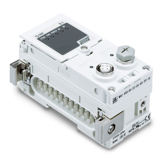
- Page 17 SI Unit Model Indication and How to Order EX600- S EN 3 -X80 SI Unit Output type / Number of ports Symbol Content Protocol PNP (negative common) / 2 port Symbol Content EtherNet/IP Summary of Product parts Description Function Status display LED Displays the status of the unit.
- Page 18 Mounting and Installation ■Wiring ○Connector pin assignment Configuration Pin No. Signal name BUS IN/BUS OUT ●Precautions for handling Be sure to fit a seal cap on any unused connectors. Proper use of the seal cap enables the enclosure to achieve IP67 specification. -17- No.EX※※-OMX1011...
- Page 19 Setting and Adjustment Switch operation (1) Loosen the display cover screw (indicated by arrow). (2) Open the display cover using a flat head screwdriver, etc. (3) Set the switch using a small watchmaker's screwdriver with a thin blade, referring to the setting of switch on the following pages.
- Page 20 Switch setting Settings1 Settings2 Hold/Clear setting Diagnostics setting •IP address byte 4 setting •DHCP mode setting Reserved IP address byte 3 setting ●Precautions for handling •Handle the switch with care. Excessive force can break the switch. •3 to 7 of the Settings1 switch are not used. (Never turn it ON.) •HOLD/CLEAR switch: Sets the output status when the fieldbus has a communication error or is in idling state.
- Page 21 •IP address setting switch Settings1 Settings2 IP address Subnet mask 192.168.0.1 192.168.0.2 255.255.255.0 192.168.0.253 192.168.0.254 192.168.1.1 192.168.1.2 255.255.255.0 192.168.1.253 192.168.1.254 1 ON/OFF DHCP mode 2 ON/OFF Remote Control mode 1: The mode to obtain IP address from DHCP server. Obtained IP address etc. is lost when the power supply is cut. 2: The mode to respond to the commands below of BOOTP/DHCP Server provided by Rockwell Automation.
- Page 22 Setting method of IP address by BOOTP/DHCP Server •When BOOTP/DHCP Server starts up, the Server scans the devices connected to the network. •After selecting the MAC address of EX600, IP address is set. •IP address is set and added to the list. -21- No.EX※※-OMX1011...
- Page 23 LED Display LED display shows the power supply and communication status. Display Content ST(M) Displays the diagnosis status of the unit. Displays the status of the power supply voltage for control and input. PWR(V) Displays the status of the power supply voltage for output. Displays the module status.
- Page 24 •PWR-LED LED display Content The power supply voltage for control and input is properly. Green ON The power supply voltage for control and input is out of range. (When diagnostic parameter is enabled) Red ON •PWR(V)-LED LED display Content The power supply voltage for output is OFF or out of range. (When diagnostic parameter is disabled) The power supply for output is properly.
- Page 25 •NS-LED LED display Content IP address is not set. EtherNet/IP communication is not established. Green flashing EtherNet/IP communication is established. Green ON EtherNet/IP communication is time-out. Red flashing IP address is duplicated. Red ON •Communication status LED display Content Bus IN side :No Link, No Activity Green ON Bus IN side : Link, No Activity (100 Mbps)
- Page 26 Specification ■Specifications Model EX600-SEN3-X80 EtherNet/IP Protocol (Conformance version: Composite 11) Standard EtherNet cable Transmission medium (CAT5 or more, 100BASE-TX) Transmission speed 10 / 100 Mbps Transmission type Full duplex / Half duplex Setting by SI unit switch: 192.168.0 or 1.1 to 254 IP address setting range Via DHCP server: Arbitrary address Vendor ID: 7 (SMC Corporation)
- Page 27 ■Dimensions -26- No.EX※※-OMX1011...
- Page 28 End plate Model Indication and How to Order EX600-ED - End plate at D side Mounting method Symbol Description Connector No DIN rail bracket Symbol Connector Key type Function With DIN rail bracket (VQC/SV/S0700 valve) M12 (5 pin) B code With DIN rail bracket (SY/JSY valve) 7/8 inch (5 pin)
- Page 29 Summary of Product parts •EX600-ED2- •EX600-ED3- •EX600-EU1- Description Function Power connector Connector for power supply to SI unit and I/O unit. Fixing hole for direct mounting Holes for direct mounting. DIN rail fixing hole Holes for fix DIN rail mounting. Functional Earth terminal - must be connected directly to system earth ...
- Page 30 •EX600-ED4/ED5- Description Function Power connector (PWR IN) Supplies power for each unit and input/output devices. Power connector (PWR OUT) Provides power to downstream equipment. Fixing hole for direct mounting Holes used for direct mounting. DIN rail fixing hole Holes used for fix DIN rail. Functional Earth terminal - must be connected directly to system earth ...
- Page 31 Mounting and Installation ■Wiring ○Connector pin assignment (1) EX600-ED2- PWR IN: M12 5-pin Plug B code Configuration Pin No. Signal name 24 V (Output) 0 V (Output) 24 V (Control and input) (Control and input) F.E. (2) EX600-ED3- PWR IN: 7/8 inch 5-pin Plug Configuration Pin No.
- Page 32 ○Regarding the 2 types of power supply The power supply consists of two power supply systems as follows: •Power supply for control and input: Supplying power for control of each unit’s power supply for control and also for device connected to input port of Digital and Analogue unit.
- Page 33 Specification ■Specifications Model EX600-ED2- EX600-ED3- EX600-ED4- EX600-ED5- M12 (5 pin) 7/8 inch (5 pin) M12 (4-pin) M12 (4-pin) PWR IN Plug Plug Plug Plug Power connector M12 (5-pin) M12 (5-pin) PWR OUT Socket Socket Power supply 24 VDC ±10%, 24 VDC ±10%, DC24 V ±10%, 4 A (Control and input) 24 VDC +10/-5%,...
- Page 34 ■Dimensions •EX600-ED2 •EX600-ED2-2 -33- No.EX※※-OMX1011...
- Page 35 •EX600-ED2-3 -34- No.EX※※-OMX1011...
- Page 36 •EX600-ED3 •EX600-ED3-2 -35- No.EX※※-OMX1011...
- Page 37 •EX600-ED3-3 -36- No.EX※※-OMX1011...
- Page 38 •EX600-ED4/ED5 •EX600-ED4/ED5-2 -37- No.EX※※-OMX1011...
- Page 39 •EX600-ED4/ED5-3 -38- No.EX※※-OMX1011...
- Page 40 •EX600-EU1 •EX600-EU1-2 -39- No.EX※※-OMX1011...
- Page 41 IO-Link Master Unit Model Indication and How to Order EX600- L A B 1 IO-Link master Number of ports and connector Symbol Number of ports Connector Port specifications 4 ports M12 connector Symbol Content Port Class A Port Class B Summary of Product parts •EX600-L#B1 Description...
- Page 42 Mounting and Installation ■Wiring ○Connector pin assignment (1) EX600-LAB1 M12 5-pin Socket Configuration Pin No. Signal name Details 24 V (Control and input) Digital input (PNP) 0 V (Control and input) IO-Link communication, Digital input (PNP) or 1 Digital output (PNP) N.C.
- Page 43 LED display The LED displays the status of Pin No.4 (C/Q) and Pin No.2 (I/Q or P24) of each IO-Link port of the SI unit. The figures below show the status of each port. •EX600-LAB1 •EX600-LBB1 Common for IO-Link port No. 1, 2, 3 and 4 (C/Q: Pin No.4) of EX600-LAB1 and EX600-LBB1 The LED status varies depending on the setting of Pin No.4 (disabled, IO-Link communication, digital I/O) of ports No.
- Page 44 LED 1, 2, 3, 4 (I/Q: Pin No. 2) for EX600-LAB1 The LED displays the status of Pin No.2 (Digital input) of each IO-Link port of the SI unit. Pin function LED status Details Input signal OFF (Digital input) Input signal ON Orange ON : For details and countermeasures, refer to troubleshooting.
- Page 45 Specification ■Specifications Model EX600-LAB1 EX600-LBB1 Port class Class A Class B COM1 (4.8 kbps) COM2 (38.4 kbps) Transmission speed COM3 (230.4 kbps) Automatically switches depending on the device connected IO-Link version Version 1.1 Number of ports Power supply for control and inputs 0.5 A / connector 0.5 A / connector Max.
- Page 46 ■Dimensions •EX600-L#B1 -45- No.EX※※-OMX1011...
- Page 47 Maintenance Turn OFF the power supply, stop the supplied air, exhaust the residual pressure and verify the release of air before performing maintenance. Cleaning method Use a soft cloth to remove stains. For heavy stains, use a cloth soaked with diluted neutral detergent and fully squeezed, then wipe up the stains again with a dry cloth.
- Page 48 Troubleshooting •Troubleshooting When any failure happens with this Fieldbus system, the following chart is used to identify the cause of the failure. Error status is reflected from the parameter setting of the Fieldbus system. When a failure occurs, take the appropriate countermeasures referring to the LED display, the troubleshooting and the parameter setting.
- Page 49 SI unit Refer to Fault 9 Red ST(M) LED is flashing. Red ST(M) LED is ON. Refer to Fault 10 Or red/green ST(M) LED is flashing alternately. Red PWR or PWR(V) Refer to Fault 11 LED is ON. L/A IN or L/A OUT Refer to Fault 12 LED is ON or OFF.
- Page 50 •Trouble counter measure method Part No. Problem Presumed cause Troubleshooting EX600- Power supply for control LED is OFF. Check if the power for control and input is supplied. and input is OFF. Check the parts with error by using the LED display or Red LED is ON.
- Page 51 Part No. Problem Presumed cause Troubleshooting EX600- Check the parts with error by using the LED display or Red LED is ON. Output device is unit diagnostic data or master. Re-wire the (Diagnosis is short-circuited. short-circuited part or check if the cable and output activated) device are normal.
- Page 52 Part No. Problem Presumed cause Troubleshooting EX600- Check the parts with error by using the LED display or Red LED is ON. Analogue input device unit diagnostic data or master. Re-wire the (Diagnosis is power supply is short-circuited part, and check if the cable and analogue activated) short-circuited.
- Page 53 Part No. Problem Presumed cause Troubleshooting EX600- Check the parts with error by using the LED display or Red LED is ON. Analogue input or output unit diagnostic data or master. Re-wire the (Diagnosis is device power supply is short-circuited part, and check if the cable and analogue activated) short-circuited.
- Page 54 Problem Presumed cause Troubleshooting Check the parts with error by using the LED display or (1)Valve is short-circuited. unit diagnostic data or master. Red ST(M) LED is (2)Valve is open-circuited. (1)Check the operation after replacing the valve. flashing. (3)ON/OFF count of the (2)Check the operation after replacing the valve.
- Page 55 Problem Presumed cause Troubleshooting (1)Configuration is not (1)Set the configuration properly. Refer to "Hardware MS: Green LED is correctly. Configuration" (page 89) for details. flashing (2)The master is idle (2)Set the PLC to RUN status. state. Diagnostic error is Check the LED status and eliminate the error MS: Red LED is flashing detected.
- Page 56 Problem Presumed cause Troubleshooting If the polarity (PNP, NPN) of the input unit and the input Polarity of input does not device are different, replace one of them to make the match. combination match. Check if the green PWR LED of the SI unit is ON. If the Power supply for control LED is off, or the red LED is ON, supply 24 VDC ±10% and input is out of range.
- Page 57 Problem Presumed cause Troubleshooting Check if the green PWR LED of the SI unit is ON. If the Power supply for control LED is off, or the red LED is ON, supply 24 VDC ±10% and input is out of range. to the power supply for control and input.
- Page 58 Problem Presumed cause Troubleshooting LED (C/Q) of In IO-Link mode, •IO-Link device EX600-L B1 is flashing Connect the IO-Link device. green (1Hz). disconnected. In IO-Link mode, •Check the setting of Validation and Backup. •Connected IO-Link •Check the process data of each port of the IO-Link LED (C/Q) of device matching error.
- Page 59 The EX600 parameters can be configured for the system, each unit and each channel. Parameters can be changed by EtherNet/IP Object or Web server. ■Parameter definition and setting With EX600 series, parameters can be set for each unit. The table below shows settable parameters for the SI unit and input/output units. •System parameters Default...
- Page 60 •SI unit parameters (1) Default Parameter Parameter Definition Item Content setting setting range Generated error Enable Generates an error. Power supply when control and for control and input power supply Unit input voltage voltage goes over Does not generate an monitor approx.
- Page 61 •SI unit parameters (2) Default Parameter Parameter Definition Item Content setting setting range Generates an error. Generates error Enable Valve 4 Val: 1 to 65000 when the operation ON/OFF Channel count exceeds the Does not generate an counter Disable 3 set value.
- Page 62 •Digital input unit parameters Default Parameter Parameter Definition Item Content setting setting range The power Generates error Enable Generates an error. supply short when the short circuit circuit of the power Unit detection for supply for the input Does not generate an control and Disable device is detected.
- Page 63 •Digital output unit parameters Default Parameter Parameter Definition Item Content setting setting range Generates error Enable Generates an error. Output load when the short short circuit circuit of the output Unit Does not generate an detection device is detected. Disable 1 error.
- Page 64 •Digital I/O unit parameters (1) Default Parameter Parameter Definition Item Content setting setting range The power Generates error Enable Generates an error. supply short when the short circuit circuit of the control Unit detection for or input power Does not generate an control and Disable supply is detected.
- Page 65 •Digital I/O unit parameters (2) Default Parameter Parameter Definition Item Content setting setting range Generates an error. Input or Generates error Enable 5 Val: 1 to 65000 Output when the operation Channel ON/OFF count exceeds the Does not generate an ...
- Page 66 •Analogue input unit parameters Default Parameter Parameter Definition Item Content setting setting range The power Generates error Enable Generates an error. supply short when the short circuit circuit of the power Unit detection for supply for the input Does not generate an the input Disable device is detected.
- Page 67 Table. Settable range of user set value Settable value range Range Lower limit Upper limit -10..+10 V -10.50 to +10.45 V -10.45 to +10.50 V -5..+5 V -5.25 to +5.22 V -5.22 to +5.25 V -20..+20 mA -21.00 to +20.90 mA -20.90 to +21.00 mA 0..10 V 0.00 to +10.45 V...
- Page 68 •Analogue output unit parameters (1) Default Parameter Parameter Definition Item Content setting setting range The power Enable Generates an error. supply short Generates error circuit when the short Unit detection for circuit of the output Does not generate an the output device is detected.
- Page 69 •Analogue output unit parameters (2) Default Parameter Parameter Definition Item Content setting setting range Output will be user idle Output setting Enable Sets output during 1 value. communication Channel communication Output will be held last idling. Disable idling state.
- Page 70 Scaled data format Function to set any value between "-32767 to 32767" as the AD value for output signal range. Resolution is determined by specifying the upper and lower scale limit. Upper limit value of the range - Lower limit value of the range Resolution = Upper limit value of the scale - Lower limit value of the scale Example: when the range is 1 to 5 V output...
- Page 71 •Analogue I/O unit parameters (1) Default Parameter Parameter Definition Item Content setting setting range The power Generates error Enable Generates an error. supply short when the short circuit circuit of the input Unit detection for device power Does not generate an the input or supply or output Disable...
- Page 72 •Analogue I/O unit parameters (2) Default Parameter Parameter Definition Item Content setting setting range Generates error 1 Enable Generates an error. User’s set when the input or value lower output value falls Does not generate an limit error below the lower ...
- Page 73 Settable range for user set upper or lower limit and output value at communication error and idling Settable range for output Settable range for user set upper or lower limit Range value at communication error Lower limit Upper limit and idling 0..10 V 0.00 to +10.45 V +0.05 to +10.50 V...
- Page 74 Scaled data format Function to set any value between "-32767 to 32767" as the AD value for I/O signal range. Resolution is determined by specifying the upper and lower scale limit. Upper limit value of the range - Lower limit value of the range Resolution = Upper limit value of the scale - Lower limit value of the scale Example: when the range is 1 to 5 V output...
- Page 75 •IO-Link master unit parameters Default Parameter Parameter Definition Item Content setting setting range I/O size of port 1 to 4: 2/2/2/2 byte 2 byte/2 byte for each I/O size of port 1 to 4: 4/4/4/4 byte 4 byte/4 byte for each Define the process I/O size of port 1 to 4: 8/8/8/8 byte...
- Page 76 •IO-Link master unit parameters (continued) Default Parameter Parameter Definition Item Content setting setting range Turn OFF the digital Clear output. Output setting Set the digital during output signal when Maintain the digital output Communication an EtherNet/IP Hold that the IO-Link master Unit Fault communication...
- Page 77 •IO-Link master unit parameters (continued) Default Parameter Parameter Definition Item Content setting setting range No Device Comparison function: invalid Check DS function: invalid Connected device: V1.0 Type compatible Comparison function: valid Device V1.0 DS function: invalid Set the function of the comparison Connected device: V1.1 Type compatible...
- Page 78 Output setting / IO-LINK communication mode when the EtherNet/IP communication error is generated or idling When the EtherNet/IP communication is abnormal or idling, the connected device will operate as follows based on the IO-Link master setting. IO-Link master setting (Output setting when master communication is abnormal or is idling) Operation of the connected device Setting item Details...
- Page 79 Port cycle time setting The communication cycle time automatically sets the port cycle time, or it sets in the range of 0.4 ms to 132.8 ms with the value of 0 to 255. Note) The settable minimum cycle time varies depending on the IO-Link device minimum cycle time, communication speed and process data size.
- Page 80 Data storage function When the IO-Link port operation mode is set to "IOL_Manual", and in addition to this, when Validation & Backup is set to "Type compatible, Device V1.1, Backup + Restore" or "Type compatible, Device V1.1, Restore", the data storage function is available. •Outline of backup or re-storage The parameter set data in each IO-Link device can be stored (referred to as "backup") in the IO-Link master.
- Page 81 I/O Map Allocated input and output bytes of each unit type Allocated input and output size is changable according to the diagnosis setting and connected EX600 unit type. The allocated input and output bytes for each EX600 unit are shown below. Allocated bytes Unit Unit part number...
- Page 82 I/O map example EX600 I/O data is mapped from unit 0 in order, and when the diagnostics is valid, the diagnostic data is mapped on top of the input data. At the same time, when the I/O data size is set, the following precautions should be followed.
- Page 83 <Example 2> Unit 0 Unit 1 Unit 2 Unit 3 Unit 4 Unit 5 DY#B DY#B DX#B DX#D SEN3 Analogue Digital Digital Digital Digital SI unit input output output input input End plate Valve 4 byte 1 byte 2 byte Input Input Input...
- Page 84 <Example 3> Unit 0 Unit 1 Unit 2 Unit 3 Unit 4 DX#B DY#B LAB1 LBB1 SEN3 Digital Digital IO-Link IO-Link SI unit input input Class A Class B End plate Valve 1 byte 44 byte 44 byte Input Input Input 1 byte 44 byte...
- Page 85 Details of I/O map of the IO-Link master unit I/O map of the IO-Link master unit is described below. (Common for EX600-LAB1 and EX600-LBB1) Input Output Byte 0 Port 4 Port 3 Port 2 Port 1 Port 4 Port 3 Port 2 Port 1 Byte 1...
- Page 86 •A mapping example is shown below when the process data mapping is set to port 2 byte Input data Output data Byte 0 Port 4 Port 3 Port 2 Port 1 Port 4 Port 3 Port 2 Port 1 Byte 1 (fixed value: 0) (fixed value: 0) Byte 2...
- Page 87 Diagnosis By changing the diagnosis switch, the diagnostic data shown below is assigned to the head of input data of the I/O map. (Refer to "Setting and adjustment (page 19)" for setting the switch.) Mode Diagnostic data Diagnostic size No diagnostic data. 0 byte System diagnosis + Unit diagnosis 4 bytes...
- Page 88 ■Details of diagnostic data Diagnostic data Byte Bit No. Diagnostic content The analogue value has fallen below the user set value. The analogue value has exceeded the user set value. The analogue input value has fallen below the set range. The analogue input value has exceeded the set range.
- Page 89 ■Diagnosis of IO-Link master unit data The EX600 IO-Link master unit secures the diagnostic function in each port, communication is performed with LED display and process data input (PQI) in accordance with the diagnostics. The LED display, PQI and even code of each diagnostic are shown below. Port LED Port diagnostics function Details...
- Page 90 EX600 on the configure. EDS file: ex600_sen_3_4_v10.eds Icon: ex600_1.ico ■Setting using Logix Designer When connecting EX600 series, use Logix Designer software by Rockwell Automation. Refer to the manual of Logix Designer for a detailed manner of operation. 1. Example of setting using EDS file •Select [EDS Hardware Installation Tool] from the [Tools] menu.
- Page 91 •Select the EDS file to be installed, and select [Next]. •Right-click on the selection [Ethernet] in the [I/O Configuration] folder, and select [New Module]. -90- No.EX※※-OMX1011...
- Page 92 •The [Select Module Type] screen is displayed. Select [EX600-SEN3/4] and select [Create]. •When the [New Module] screen is displayed, input the information below. (1) Name: Enter the required unit name. (2) Module Description: Input/Output data size which is actually connected when the [Change] button is pressed.
- Page 93 2. Example of setting using the Generic Ethernet Module •Right-click on the selection [Ethernet] in the [I/O Configuration] folder, and select [New Module]. •The [Select Module Type] screen is displayed. Select [Generic Ethernet Module] and select [Create]. -92- No.EX※※-OMX1011...
- Page 94 •The [Module Properties] screen is displayed, to perform setup. (1) Name: Enter the required unit name. (2) Select the data format of Comm: Connection Parameters. (3) IP Address: Enter the IP address setting for the SI unit. (4) Assembly Instance: Perform setting as shown below. Description Decimal Common Format...
- Page 95 Configuration assembly ■Parameter setting of EX600 with configuration assembly The Configuration assembly function enables PCL to send parameters to the EX600 under the EtherNet/IP communication connection. : This function may not be available due to the PLC type. : The settable data size in the configuration assembly is 456 bytes maximum. •Unit ID list Each unit has an individual unit ID.
- Page 96 •EtherNet/IP configuration assembly The Configuration data per unit type is described below. Configuration format (EX600-SEN3-X80) EX600-SEN3-X80 (27 byte) Byte Parameter Setting value 0..3 Unit No. 0..9 4..7 Parameter type 0..7 Unit ID 9B (Hex) Unit parameter Reserved Monitor short circuit (Output) 0: disable, 1: enable Reserved Restart after short circuit...
- Page 97 Configuration format (EX600-DX#B/C) EX600-DX#B/C (4 byte) Byte Parameter Setting value 0..3 Unit No. 0..8 4..7 Parameter type EX600-DX#B: 01 (Hex) 0..7 Unit ID EX600-DX#C: 03 (Hex) Unit parameter Monitor short circuit (power) 0: disable, 1: enable Reserved Inrush current filter 0: disable, 1: enable Reserved 4..5...
- Page 98 Configuration format (EX600-DX#D/E/F) EX600-DX#D/E/F (5 byte) Byte Parameter Setting value 0..3 Unit No. 0..8 4..7 Parameter type EX600-DX#D: 05 (Hex) 0..7 Unit ID EX600-DX#E: 14 (Hex) EX600-DX#F: 16 (Hex) Unit parameter Monitor short circuit (power) 0: disable, 1: enable Reserved Inrush current filter 0: disable, 1: enable Reserved...
- Page 99 Configuration format (EX600-DY#B) EX600-DY#B (9 byte) Byte Parameter Setting value 0..3 Unit No. 0..8 4..7 Parameter type 0..7 Unit ID 08 (Hex) Unit parameter Reserved Monitor short circuit (out) 0: disable, 1: enable Reserved Restart after short circuit 0: manual, 1: auto 4..7 Reserved Channel parameter –...
- Page 100 Configuration format (EX600-DY#E/F) EX600-DY#E/F (15 byte) Byte Parameter Setting value 0..3 Unit No. 0..8 4..7 Parameter type EX600-DY#E: 18 (Hex) 0..7 Unit ID EX600-DY#F: 1A (Hex) Unit parameter Reserved Monitor short circuit (out) 0: disable, 1: enable Reserved Restart after output load short circuit 0: manual, 1: auto 4..7 Reserved...
- Page 101 Configuration format (EX600-DM#E/F) EX600-DM#E/F (10 byte) Byte Parameter Setting value 0..3 Unit No. 0..8 4..7 Parameter type EX600-DM#E: 1C (Hex) 0..7 Unit ID EX600-DM#F: 1E (Hex) Unit parameter Monitor short circuit (power) 0: disable, 1: enable Monitor short circuit (out) 0: disable, 1: enable Inrush current filter 0: disable, 1: enable...
- Page 102 Configuration format (EX600-AXA) EX600-AXA (14 byte) Byte Parameter Setting value 0..3 Unit No. 0..8 4..7 Parameter type 0..7 Unit ID 20 (Hex) Unit parameter Monitor short circuit 0: disable, 1: enable 1..3 Reserved (Ch0&1 in) Monitor over range 0: disable, 1: enable (Ch0&1 in) Monitor under range 0: disable, 1: enable 0: offset binary, 1: signed magnitude,...
- Page 103 Configuration format (EX600-AYA) EX600-AYA (21byte) Byte Parameter Setting value 0..3 Unit No. 0..8 4..7 Parameter type 0..7 Unit ID 22 (Hex) Unit parameter Monitor short circuit 0: disable, 1: enable 1..5 Reserved 0: offset binary, 1: signed magnitude, 6..7 Analogue data format 2: 2’s complement, 3: Linear scaled, Channel parameter –...
- Page 104 Configuration format (EX600-AMB) Byte 0 to 6 EX600-AMB (32 byte) Byte Parameter Setting value 0..3 Unit No. 0..8 4..7 Parameter type 0..7 Unit ID 23 (Hex) Unit parameter Monitor short circuit 0: disable, 1: enable 1..3 Reserved (Ch0&1 in) Monitor over range 0: disable, 1: enable (Ch0&1 in) Monitor under range 0: disable, 1: enable...
- Page 105 Configuration format (EX600-AMB) Byte 7 to 31 EX600-AMB (32 byte) Byte Parameter Setting value (Ch0 out) 0: hold, 1: depend on fault value Output setting for communication fault (Ch1 out) 0: hold, 1: depend on fault value Output setting during communication Fault (Ch0 out) 0:disable, 1:enable Monitor upper limit value...
- Page 106 Configuration format (EX600-LAB1 / EX600-LBB1) Byte 0 to 5 EX600-LAB1 / EX600-LBB1 (46 byte) Byte Parameter Setting value 0..3 Unit No. 0..8 4..7 Parameter type EX600-LAB1:3B (Hex) 0..7 Unit ID EX600-LBB1:3C (Hex) Unit parameter Monitor short circuit 0: disable, 1: enable Reserved 2..3 Byte swap...
- Page 107 Configuration format (EX600-LAB1 / EX600-LBB1) Byte 6 to 45 EX600-LAB1 / EX600-LBB1 (46 byte) Byte Parameter Setting value PortConfig – Port 1 0: Deactivated 1: IOL_Manual 0..7 PortMode 2: IOL_Autostart 3: DI_C/Q 4: DQ_C/Q 0: No Device Check 1: Type compatible Device V1.0 2: Type compatible Device V1.1 0..7 Validation&Backup...
- Page 108 ■Parameter setting of IO-Link device with configuration assembly The Configuration assembly function enables PCL to send parameters to the IO-Link device, which is connected to the IO-Link master, under the EtherNet/IP communication connection. Set the Index, subindex and data to be changed by specifying the Unit No., Unit ID and IO-Link port in accordance with the Operation Manual of the IO-Link device.
- Page 109 ■Configuration assembly setting method example The parameter setting for the manifold using Rockwell Automation Logix Designer is described below. Unit 0 Unit 1 Unit 2 Unit 3 LAB1 SEN3-X80 Analog Analog IO-Link SI unit Valve manifold Input (32 outputs) plate (32 coils) Config size Config size...
- Page 110 (1) Preparation of configuration data Prepare the following configuration data with reference to page to 107. Refer to the Operation Manual of the IO-Link device for the index, subindex and set value required for setting the parameter of the IO-Link device.
- Page 111 (2) Configuration size setting Enter the byte size of the configuration data, which has been prepared in (1), in the Configuration size column of the Connection Parameters. The settable data size in the configuration assembly is 456 bytes maximum. (3) Controller Tags Set the data for 88 bytes to the Value of Tags.
- Page 112 ■Device Level Ring (DLR) function This SI unit can be used as an EtherNet/IP compliant node for network rings with the DLR function. To enable the DLR function, all of the ring nodes need to be applicable to the DLR function. Since all of the DLR function settings are performed by the Ring Supervisor, there is no need to perform any settings to the SI unit.
- Page 113 2. QuickConnect function setting Change the TCP/IP Object to the values shown below. Make sure the value is set to "0" when the QuickConnect function is not used. Class Instance Attribute Value QuickConnect setting 0: disabled (default setting) 0xF5 0x01 0X0C ○...
- Page 114 EtherNet/IP Object System diagnostic object (Class: 66h) Instance Attribute Access Name Type Value Input data length UINT I/O mapping input data length (Byte) Output data length UINT I/O mapping output data length (Byte) Number of units USINT Number of units connected connected 0: switch Get/Set...
- Page 115 Unit/Channel diagnosis object (Class: 67h) Instance Attribute Access Name Type Value 0: No error, 1: Error Bit0: The analogue value has fallen below the user set value. Bit1: The analogue value has exceeded the user set value. Bit2: The analogue input value has fallen below the set range. Bit3: The analogue input value has exceeded the set range.
- Page 116 Details of channel diagnosis object (Class: 77h) Instance Attribute Access Name Type Value 0: No error, 1: Error Bit0: The analogue value has fallen below the user set value. Bit1: The analogue value has exceeded the user set value. Bit2: The analogue input value has fallen below the set range. 01h to 64h to Bit3: The analogue input value has exceeded the set range.
- Page 117 Unit parameter object (Class: 78h) Instance Attribute Access Name Type Value Short circuit detection (Power supply for input device) 0: Disable BOOL 1: Enable •Digital input, I/O •Analogue input, output, I/O Short circuit detection (Output) 0: Disable BOOL •SI 1: Enable •Digital output, I/O Analogue over range detection 0: Disable...
- Page 118 Unit parameter object (Class: 78h) Instance Attribute Access Name Type Value 0: Clear / PD Out valid IO-Link master BOOL 1: Hold •Fault output (IO-Link) 2: Clear/ PD Out invalid 0: Clear IO-Link master BOOL 1: Hold •Fault output (DO) 2: Force ON 0: Clear / PD Out valid IO-Link master...
- Page 119 Channel parameter object (1) (Class: 79h to 7Fh) Class Instance Attribute Access Name Type Value Open circuit detection 0: Disable •SI BOOL 1: Enable •Digital input (DX#C1) •Digital output, I/O ON/OFF count upper limit detection 0: Disable BOOL 1: Enable •SI •Digital input, output, I/O ON/OFF count upper limit value...
- Page 120 Channel parameter object (2) (Class: 83h to 8Ah) Class Instance Attribute Access Name Type Value Output setting at communication error 0: Disable (Hold) BOOL 1: Enable •SI (Clear or Force ON) •Digital output, I/O •Analogue output, I/O Output setting at communication error (Digital) 0: Off (Clear) BOOL...
- Page 121 ■IO-Link SMI service Reading and writing of the IO-Link master and device parameter using EtherNet/IP Explicite Message. The service code of the Explicit Message varies in reading and writing. •Reading: 32h •Writing: 33h The following 5 types of data can be read or written in the SMI service. Description Data type Read...
- Page 122 2-1. SMI_PortConfigList (acquires IO-Link master port parameter: Read) [Request] Data Value Notes Service code 0x32 Class 0x90 Instance 0x01 to 09 Unit No. +1 Attribute 0x65 to 68 Port No. 1 to 4 Data[0] 0x80 Fixed value Data[1] 0x00 Fixed value [Response] 備考...
- Page 123 2-2. SMI_PortConfigList (acquires IO-Link master port parameter: Write) [Request] Data Value Notes Service code 0x33 Service code Class 0x90 Class Instance 0x01 to 09 Instance, unit No.+1 Attribute 0x65..68 Port No. 1 to 4 Data[0] 0x80 Fixed value Data[1] 0x00 Fixed value 0: Deactivated 1: IOL_Manual...
- Page 124 3. SMI_PortStatusList (Acquires IO-Link master port status: Read) [Request] Data Value Notes Service code 0x32 Class 0x90 Instance 0x01 to 09 Unit No.+1 Attribute 0x65 to 68 Port No. 1 to 4 Data[0] 0x90 Fixed value Data[1] 0x00 Fixed value [Response] Data Value...
- Page 125 4. SMI_DeviceRead (Acquires IO-Link device marameters: Read) [Request] Data Value Notes Service code 0x32 Class 0x90 Instance 0x01 to 09 Unit No. +1 Attribute 0x65 to 68 Port No. 1 to 4 Data[0] 0x30 Fixed value Data[1] 0x00 Fixed value Data[2] Index[0] (MSB) Refer to the Operation Manual of the IO-Link Device...
- Page 126 Web Server EX600 Web server functional overview The Web server function is provided by the EX600-SEN3-X80. The functions available vary depending on the mode. Function Admin mode Monitor only mode I/O Monitor Available Available Diagnostic status monitor Available Available Parameter setting Available Not available Force I/O setting...
- Page 127 (4) When [Login] is selected after inputting Password, the screen below is displayed. Press the [Next] button. NOTE The parameter setting is available with Admin mode only. -126- No.EX※※-OMX1011...
- Page 128 (5) After pressing the [Next] button, the [SYSTEM CONFIGURATION STATUS] screen is displayed. This screen will be the TOP screen. The total size of input/output is displayed. When selecting the Unit Name, I/O monitor screen is displayed. When the Password is changed and Error Log is cleared, click here. Click here to logout.
- Page 129 (6) When unit diagnostics is generated, the diagnostic information is displayed on the [SYSTEM CONFIGURATION STATUS] screen. The unit which requires a diagnostics can be specified. When selecting [LOG], the error log information is displayed. -128- No.EX※※-OMX1011...
- Page 130 (7) When [Unit Name] is selected on the [SYSTEM CONFIGURATION STATUS] screen, the [I/O MONITOR] screen is displayed. (EX600-DX D) ON/OFF information can be monitored for each channel. Select here when selecting the channel to be displayed. Channels which require diagnostic and detailed diagnostic information are displayed.
- Page 131 (8) Select the [UNIT PARAMETER] tab to display the [UNIT PARAMETER] screen. (EX600-LAB1) When the [SET] button is selected after changing the set value, the parameter will be changed. -130- No.EX※※-OMX1011...
- Page 132 (9) Select the [CHANNEL PARAMETER] tab to display the [CHANNEL PARAMETER] screen. (EX600-LAB1) When the [SET] button is selected after changing the set value, the parameter will be changed. -131- No.EX※※-OMX1011...
- Page 133 (10) Select the [FORCE MODE] tab to display the [FORCE MODE] screen. (EX600-DX D) Select the ON button to turn this ON. When it is confirmed that there are no abnormalities with the unit after turning it ON, select the [OK] button. -132- No.EX※※-OMX1011...
- Page 134 (11) To change the Password, select [Admin Manager] and select [Change Password]. Input the old password first and the new password twice, and select [Store] to change the password. NOTE Do not logout using the [x] button shown at the upper right of the screen. This can cause a malfunction.
- Page 135 Accessories For the selection of accessories, refer to the catalog. (1)Valve plate EX600-ZMV1 Enclosed parts: Round head screw (M4 x 6), 2 pcs. Round head screw (M3 x 8), 4 pcs. EX600-ZMV2 (Specified for SY series) Enclosed parts: Round head screw (M4 x 6), 2 pcs. Round head screw (M3 x 8), 4 pcs.
- Page 136 (4)Seal cap (10 pcs.) EX9-AWES: For M8 EX9-AWTS: For M12 (5)Marker (1 sheet, 88 pcs.) EX600-ZT1 (6)Assembled type connector PCA-1446553: For EtherNet/IP communication, M12 (4 pin) Plug, D code PCA-1578078: For power supply, 7/8 inch, Plug, Cable O.D. 12 to 14 mm PCA-1578081: For power supply, 7/8 inch, Socket, Cable O.D.
- Page 137 Revision history 4-14-1, Sotokanda, Chiyoda-ku, Tokyo 101-0021 JAPAN Tel: + 81 3 5207 8249 Fax: +81 3 5298 5362 https://www.smcworld.com Note: Specifications are subject to change without prior notice and any obligation on the part of the manufacturer. EtherNet/IP™ is a trademark of ODVA The descriptions of products shown in this document may be used by the other companies as their trademarks.
Need help?
Do you have a question about the EX600 Series and is the answer not in the manual?
Questions and answers