
Related Manuals for SIGMATEK PL 221


Summary of Contents for SIGMATEK PL 221
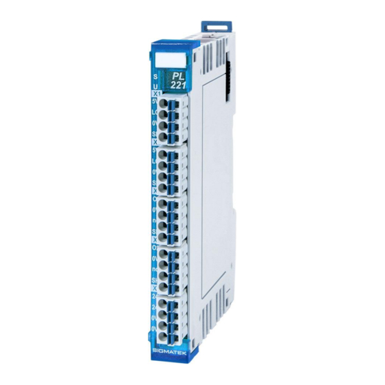
- Page 1 PL 221 S-DIAS Pixel LED Module Instruction Manual Date of creation: 13.03.2018 Version date: 26.07.2023 Article number: 20-018-221-E...
- Page 2 (print, photocopy, microfilm or in any other process) without the express permission. We reserve the right to make changes in the content without notice. The SIGMATEK GmbH & Co KG is not responsi- ble for technical or printing errors in the handbook and assumes no responsibility for damages that occur through...
- Page 3 2x RGB pixel LED strips and 2x 24 V PWM LED strips With the S-DIAS Pixel LED module PL 221, two pixel LED strips with a maximum of 512 pixel RGB LEDs each and two +24 V PWM dimmable white LED strips can be controlled.
-
Page 4: Table Of Contents
PL 221 S-DIAS PIXEL LED MODULE Contents Introduction ................5 Target Group/Purpose of this Operating Manual ...... 5 Important Reference Documentation ......... 5 Contents of Delivery ..............5 Basic Safety Directives ............6 Symbols Used ................6 Disclaimer ..................8 General Safety Directives ............ - Page 5 S-DIAS PIXEL LED MODULE PL 221 Connector Layout ..............18 Status LEDs ................. 19 Applicable Connectors ............... 20 Labeling Field ................21 Wiring ..................22 Wiring Example ................22 Notes .................... 23 Assembly/Installation ............24 Check Contents of Delivery ............24 Mounting ..................
- Page 6 PL 221 S-DIAS PIXEL LED MODULE 12.5.3 SetWholeStripe .................. 40 12.6 Private Methods ................41 12.6.1 IndividualStripeConfig ................ 41 12.7 Internal Properties ..............42 12.7.1 Setting the Color Resolution .............. 42 12.7.2 Explanation of the methods ChangeAllLEDs and ChangeIndividualLED ................ 43 12.7.3...
-
Page 7: Introduction
General knowledge of automation technology is required. Further help and training information, as well as the appropriate accessories can be found on our website www.sigmatek-automation.com. Our support team is happily available to answer your questions. Please see our website for our hotline number and business hours. -
Page 8: Basic Safety Directives
PL 221 S-DIAS PIXEL LED MODULE 2 Basic Safety Directives Symbols Used The following symbols are used in the operator documentation for warning and danger messages, as well as informational notes: DANGER Danger indicates that death or serious injury will occur, if the speci- fied measures are not taken. - Page 9 S-DIAS PIXEL LED MODULE PL 221 INFORMATION Information Provides important information on the product, handling or rele- vant sections of the documentation, which require attention. 26.07.2023 Page 7...
-
Page 10: Disclaimer
It does not guarantee properties under the warranty. Please thoroughly read the corresponding documents and this operat- ing manual before handling a product. SIGMATEK GmbH & Co KG is not liable for damages caused through, non-compliance with these instructions or applicable regulations. -
Page 11: General Safety Directives
S-DIAS PIXEL LED MODULE PL 221 General Safety Directives The Safety Directives in the other sections of this operating manual must be observed. These instructions are visually emphasized by symbols. INFORMATION According to EU Directives, the operating manual is a component of a product. -
Page 12: Software/Training
PL 221 S-DIAS PIXEL LED MODULE CAUTION Handle the device with care and do not drop or let fall. Prevent foreign bodies and fluids from entering the device. The device must not be opened! Manipulez l’appareil avec précaution et ne le laissez pas tomber. -
Page 13: Standards And Directives
3.1.1 EU Conformity Declaration EU Declaration of Conformity The product PL 221 conforms to the following European directives: • 2014/35/EU Low-voltage Directive • 2014/30/EU Electromagnetic Compatibility (EMC Directive) • 2011/65/EU “Restricted use of certain hazardous substances in electrical and electronic equipment”... -
Page 14: Type Plate
PL 221 S-DIAS PIXEL LED MODULE 4 Type Plate HW: Hardware version SW: Software version Page 12 26.07.2023... -
Page 15: Technical Data
S-DIAS PIXEL LED MODULE PL 221 Technical Data Pixel LED Outputs Specifications Number of channels Short-circuit and overload protec- yes (short-circuit or overload can be read from software through a latched tion status bit) Supported pixel LEDs WS2812B, WS2813 Maximum number of pixel LEDs... -
Page 16: Electrical Requirements
PL 221 S-DIAS PIXEL LED MODULE Electrical Requirements External +24 V supply +18-30 V DC External current consumption max. total current 5.4 A +24 V (2x pixel LED total current max. 1.4 A, 2x PWM output total current max. 4 A) - Page 17 S-DIAS PIXEL LED MODULE PL 221 26.07.2023 Page 15...
-
Page 18: Miscellaneous
PL 221 S-DIAS PIXEL LED MODULE Miscellaneous Article number 20-018-221 Approvals CE, UKCA Environmental Conditions Storage temperature -20 ... +85 °C ambient temperature 0 ... +55 °C Humidity 0-95 %, non-condensing Installation altitude above sea 0-2000 m without derating level >... -
Page 19: Mechanical Dimensions
S-DIAS PIXEL LED MODULE PL 221 Mechanical Dimensions 26.07.2023 Page 17... -
Page 20: Connector Layout
PL 221 S-DIAS PIXEL LED MODULE Connector Layout INFORMATION The connections of the +24 V supply (X4: pin 1 and pin 2) or the GND supply (X4: pin 3 and pin 4) are internally bridged. To supply the mod- ule, only one connection to a +24 V pin (pin 1 or pin 2) and a GND pin (pin 3 or pin 4) is required. -
Page 21: Status Leds
S-DIAS PIXEL LED MODULE PL 221 Status LEDs Module status green module active no supply available BLINKING (5 Hz) no communication User yellow can be set from the application (e.g. the module LED can be set to blinking through the visualiza-... -
Page 22: Applicable Connectors
PL 221 S-DIAS PIXEL LED MODULE Applicable Connectors Connectors: X1-X5: Connectors with spring terminals (included in delivery) The spring terminals are suitable for the connection of ultrasonically compressed (ultrasoni- cally welded) strands. Connections: Stripping length/sleeve length: 10 mm Mating direction:... -
Page 23: Labeling Field
S-DIAS PIXEL LED MODULE PL 221 Labeling Field Manufacturer Weidmüller Type MF 10/5 CABUR MC NE WS Article number Weidmüller 1854510000 Compatible printer Weidmüller Type Printjet Advanced 230V Article number Weidmüller 1324380000 26.07.2023 Page 21... -
Page 24: Wiring
PL 221 S-DIAS PIXEL LED MODULE Wiring Wiring Example Page 22 26.07.2023... -
Page 25: Notes
S-DIAS PIXEL LED MODULE PL 221 Notes To ensure error-free operation, a careful wiring method must be followed: • The 0 V connection of the supply voltage must be connected with the 0 V collection point over the shortest route possible. -
Page 26: Assembly/Installation
PL 221 S-DIAS PIXEL LED MODULE Assembly/Installation Check Contents of Delivery Ensure that the contents of the delivery are complete and intact. See chapter 1.3 Contents of Delivery. INFORMATION On receipt and before initial use, check the device for damage. If the device is damaged, contact our customer service and do not install the device in your system. -
Page 27: Mounting
S-DIAS PIXEL LED MODULE PL 221 Mounting The S-DIAS modules are designed for installation into the control cabinet. To mount the modules a DIN-rail is required. The DIN rail must establish a conductive connection with the back wall of the control cabinet. The individual S-DIAS modules are mounted on the DIN rail as a block and secured with latches. - Page 28 PL 221 S-DIAS PIXEL LED MODULE Recommended minimum distances of the S-DIAS modules to the surrounding components or control cabinet wall: a, b, c … distances in mm (inches) ϑ … valid ambient temperature in °C (°F) The specified installation distances may be reduced if appropriate measures and technical precautions are taken to dissipate the corresponding power loss.
-
Page 29: Addressing
S-DIAS PIXEL LED MODULE PL 221 10 Addressing Address Size Access Type Description Reset (hex) (bytes) value Configuration strips Bit 9..0: Pixel address (allowed: 0-681) Bit 12..10: LED strip selection “000“: LED strip 1 “001“: LED strip 2 “111“: LUT RAM 0000 Bit 15..13: Pixel mode... - Page 30 PL 221 S-DIAS PIXEL LED MODULE Configuration change 1 Bit 9..0: Pixel address (allowed: 0-681) Bit 12..9: LED strip selection “000“: LED strip 1 “001“: LED strip 2 “111“: LUT RAM 0080 Bit 15..13: Pixel mode “000“: 24-bit mode “001“: 16-bit mode “010“: 8-bit mode...
- Page 31 S-DIAS PIXEL LED MODULE PL 221 24-bit mode (write in 3 bytes) Bit 7..0: Pixel data BLUE Bit 15..8: Pixel data GREEN Bit 23..16: Pixel data RED 16-bit mode (write in 2 bytes) Bit 4..0: Pixel data BLUE 0xxx Bit 10..5: Pixel data GREEN Bit 15..11: Pixel data RED...
- Page 32 PL 221 S-DIAS PIXEL LED MODULE PWM 2 output high time Bit 6..0: High time Period in % 0 = 0 % high time (PWM off) 50 = 50 % high time 100 = 100 % high time Bit 7: reserved...
- Page 33 S-DIAS PIXEL LED MODULE PL 221 Pixel output 1 length 0112 Bit 9..0: Output length (allowed: 1-682) 0001 Bit 15..10: reserved Pixel output 1 length 0114 Bit 9..0: Output length (allowed: 1-682) 0001 Bit 15..10: reserved 0116 Pixel output configuration...
- Page 34 PL 221 S-DIAS PIXEL LED MODULE PWM output 2 period (50-1000) * Bit 9..0: output period 50 = 2 kHz 51 = 1.96 kHz 52 = 1.92 kHz 0126 0000 998 = 100.2 Hz 999 = 100.1 Hz 1000 = 100.0 Hz Bit 15..10: reserved...
-
Page 35: Supported Cycle Times
S-DIAS PIXEL LED MODULE PL 221 11 Supported Cycle Times 11.1 Cycle Times below 1 ms (in µs) x= supported 11.2 Cycle Times equal to or higher than 1 ms (in ms) x= supported x= supported 26.07.2023 Page 33... -
Page 36: Hardware Class Pl221
Hardware Class PL221 for the S-DIAS DMX module PL 221 This hardware class is used to control the PL 221 hardware module. The module has 2 pixel LED outputs and 2 PWM outputs. More information on the hardware can be found in the module documentation. -
Page 37: General
S-DIAS PIXEL LED MODULE PL 221 12.1 General ClassState State This server shows the actual status of the hardware class. DeviceID State The device ID of the hardware module is shown in this server. FPGAVersion State FPGA version module format 16#XY (e.g. - Page 38 PL 221 S-DIAS PIXEL LED MODULE SetAllLed Output With this server the entire LED stripe can be set to one color. normal use setting stripe 1 setting stripe 2 setting both stripes This server is used to set the color for the “SetAllLed” mode. The entire LED...
-
Page 39: Pwm Output
S-DIAS PIXEL LED MODULE PL 221 WriteDataMode Property This client is used to select how the data transfer should take place. In mode 0 a complete memory for a LED stripe can be transferred. The data are sent to the module in the defined refresh time. -
Page 40: Global Methods
PL 221 S-DIAS PIXEL LED MODULE 12.5 Global Methods The following methods can be called via the ClassState server. 12.5.1 ChangeIndividualLED This method can only be used if the client WriteDataMode has been set to 1. Transfer parameters Type Description... -
Page 41: Changeallleds
S-DIAS PIXEL LED MODULE PL 221 12.5.2 ChangeAllLEDs This method can only be used if the client WriteDataMode has been set to 0. Transfer parameters Type Description usStripeNumber USINT Indicates the LED strip that is being written with the data. -
Page 42: Setwholestripe
PL 221 S-DIAS PIXEL LED MODULE 12.5.3 SetWholeStripe This method can be used independently of the set WriteDataMode. Transfer parameters Type Description usSelectStripe USINT Specifies which LED stripe should be set to the desired color. stripe 1 stripe 2 pColorData ^void Pointer to the array, where the pixel data are stored. -
Page 43: Private Methods
S-DIAS PIXEL LED MODULE PL 221 12.6 Private Methods 12.6.1 IndividualStripeConfig If the value 2 is set at the client Stripe_Type[1,2], the function IndividualStripeConfig must be overloaded and the correct values of the used stripe type must be entered. Needed values: •... -
Page 44: Internal Properties
PL 221 S-DIAS PIXEL LED MODULE 12.7 Internal Properties 12.7.1 Setting the Color Resolution You can select 4 different data transfer settings. So this allows to specify, how many bytes are used to describe a color. In the 24 bit setting, 3 bytes of color data are transferred per LED, so that 2 colors are possible for display. -
Page 45: Explanation Of The Methods Changeallleds And Changeindividualled
S-DIAS PIXEL LED MODULE PL 221 12.7.2 Explanation of the methods ChangeAllLEDs and ChangeIndividualLED The LED data is written to a separate RAM for each LED stripe. The RAM is selected with the transfer parameter usStripeNumber. The parameter uiPixelStartAddr specifies where in the RAM the color data are written and thus which LED is written with this color. - Page 46 PL 221 S-DIAS PIXEL LED MODULE 12.7.2.1 16 bit setting With this setting, only 2 bytes of color data are transferred per LED (see memory structure 16 bits). The array (ARRAY OF UINT) is filled with the color white for 17 LEDs and then transferred in the function ChangeAllLEDs or ChangeIndividualLED.
-
Page 47: Use Of The Chaser With The Parameter Dstartoffset Or The Server Startrollingaddrstripe1,2
S-DIAS PIXEL LED MODULE PL 221 12.7.2.3 4 bit setting In this setting, 2 color data are transferred per byte. The first color address for the first LED in the lower 4 bits and the second color address in the upper 4 bits for the second LED. - Page 48 PL 221 S-DIAS PIXEL LED MODULE 12.7.3.2 Server StartRollingAddrStripe1,2 The LED pattern previously stored in RAM can be started as a running light by cyclically calling the Write method and incrementing the server. The pattern only needs to be written into the RAM stripe once.
-
Page 49: Transport/Storage
S-DIAS PIXEL LED MODULE PL 221 13 Transport/Storage INFORMATION This device contains sensitive electronics. During transport and stor- age, high mechanical stress must therefore be avoided. For storage and transport, the same values for humidity and vibration as for operation must be maintained! Temperature and humidity fluctuations may occur during transport. -
Page 50: Maintenance
PL 221 S-DIAS PIXEL LED MODULE 15 Maintenance INFORMATION During maintenance as well as servicing, observe the safety instruc- tions from chapter 2 Basic Safety Directives. 15.1 Service This product was constructed for low-maintenance operation. 15.2 Repair INFORMATION In the event of a defect/repair, send the device with a detailed error description to the address listed at the beginning of this document. - Page 51 S-DIAS PIXEL LED MODULE PL 221 Documentation Changes Change Affected Chapter Note date page(s) 16.05.2018 1.4 Miscellaneous Standard and Approvals adjusted 20.09.2018 3 Connector Layout Note added 14.11.2019 7 Supported Cycle Times Chapter added 28.02.2020 7 Supported Cycle Times Text adapted 08.09.2020...
- Page 52 PL 221 S-DIAS PIXEL LED MODULE Page 50 26.07.2023...
Need help?
Do you have a question about the PL 221 and is the answer not in the manual?
Questions and answers