
Related Manuals for SIGMATEK PW 022


Summary of Contents for SIGMATEK PW 022
- Page 1 PW 022 S-DIAS Pulse Width Module Instruction Manual Date of creation: 20.11.2017 Version date: 26.07.2023 Article number: 20-030-022-E...
- Page 2 (print, photocopy, microfilm or in any other process) without the express permission. We reserve the right to make changes in the content without notice. The SIGMATEK GmbH & Co KG is not responsible for technical or printing errors in the handbook and assumes no responsibility for damages that occur...
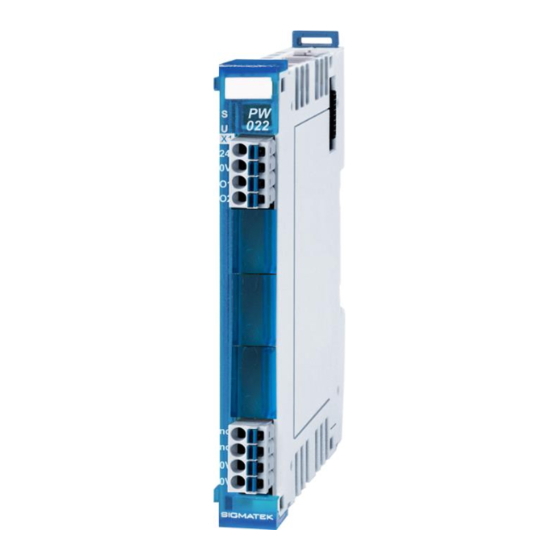
- Page 3 S-DIAS Pulse Width Module PW 022 with 2 PWM outputs The S-DIAS PW 022 pulse width module has two +24 V switching PWM outputs with an adjustable frequency for controlling inductive loads (magnetic valve, proportional valve, ...). The 2 PWM outputs are powered through a supply connection.
-
Page 4: Table Of Contents
PW 022 S-DIAS PULSE WIDTH MODULE Contents Introduction ................5 Target Group/Purpose of this Operating Manual ...... 5 Important Reference Documentation ......... 5 Contents of Delivery ..............5 Basic Safety Directives ............6 Symbols Used ................6 Disclaimer ..................8 General Safety Directives ............ - Page 5 S-DIAS PULSE WIDTH MODULE PW 022 Connector Layout ..............16 Status LEDs ................. 17 Applicable Connectors ............... 17 Label Field ................... 18 Wiring ..................19 Wiring Example ................19 Output Scheme ................20 Notes .................... 20 Assembly/Installation ............21 Check Contents of Delivery ............21 Mounting ..................
- Page 6 PW 022 S-DIAS PULSE WIDTH MODULE 15 Disposal ..................28 16 Hardware Class PW022 ............29 16.1 General ..................30 16.2 PWM Outputs 1-2 ................ 30 16.3 Communication Interfaces ............31 Page 4 26.07.2023...
-
Page 7: Introduction
General knowledge of automation technology is required. Further help and training information, as well as the appropriate accessories can be found on our website www.sigmatek-automation.com. Our support team is happily available to answer your questions. Please see our website for our hotline number and business hours. -
Page 8: Basic Safety Directives
PW 022 S-DIAS PULSE WIDTH MODULE Basic Safety Directives Symbols Used The following symbols are used in the operator documentation for warning and danger messages, as well as informational notes: DANGER Danger indicates that death or serious injury will occur, if the specified measures are not taken. - Page 9 S-DIAS PULSE WIDTH MODULE PW 022 INFORMATION Information Provides important information on the product, handling or relevant sections of the documentation, which require attention. 26.07.2023 Page 7...
-
Page 10: Disclaimer
It does not guarantee properties under the warranty. Please thoroughly read the corresponding documents and this operating manual before handling a product. SIGMATEK GmbH & Co KG is not liable for damages caused through, non-compliance with these instructions or applicable regulations. -
Page 11: General Safety Directives
S-DIAS PULSE WIDTH MODULE PW 022 General Safety Directives The Safety Directives in the other sections of this operating manual must be observed. These instructions are visually emphasized by symbols. INFORMATION According to EU Directives, the operating manual is a component of a product. -
Page 12: Software/Training
PW 022 S-DIAS PULSE WIDTH MODULE CAUTION Handle the device with care and do not drop or let fall. Prevent foreign bodies and fluids from entering the device. The device must not be opened! Manipulez l’appareil avec précaution et ne le laissez pas tomber. -
Page 13: Standards And Directives
The product was constructed in compliance with the following European Union directives and tested for conformity. 3.1.1 EU Conformity Declaration EU Declaration of Conformity The product PW 022 conforms to the following European directives: • 2014/35/EU Low-voltage Directive • 2014/30/EU Electromagnetic Compatibility (EMC Directive) •... -
Page 14: Type Plate
PW 022 S-DIAS PULSE WIDTH MODULE Type Plate HW: Hardware version SW: Software version Page 12 26.07.2023... -
Page 15: Technical Data
S-DIAS PULSE WIDTH MODULE PW 022 Technical Data PWM Output Specifications Number Configuration +24 V-switching Short-circuit proof Maximum output current/channel 1.5 A to 45 °C 1 A to 55 °C PWM frequency adjustable as period in 0.5 µs increments between 30.5 Hz and... -
Page 16: Miscellaneous
PW 022 S-DIAS PULSE WIDTH MODULE Miscellaneous Article number 20-030-022 Standard UL 508 (E247993) Approvals , UKCA Environmental Conditions Storage temperature -20 ... +85 °C Environmental temperature 0 ... +55 °C Humidity 0-95 %, non-condensing Installation altitude above sea 0-2000 m without derating level >... -
Page 17: Mechanical Dimensions
S-DIAS PULSE WIDTH MODULE PW 022 Mechanical Dimensions 26.07.2023 Page 15... -
Page 18: Connector Layout
PW 022 S-DIAS PULSE WIDTH MODULE Connector Layout INFORMATION The GND supply (X2: Pin 3 and Pin 4) is internally bridged. Only one GND pin (pin 3 or pin 4) is required to power the module. The bridged connections may be used for further looping of the GND supply. -
Page 19: Status Leds
S-DIAS PULSE WIDTH MODULE PW 022 Status LEDs Module Status green module active no supply available BLINKING (5 Hz) no communication User yellow can be set from the application (e.g. the module LED can be set to blinking through the... -
Page 20: Label Field
PW 022 S-DIAS PULSE WIDTH MODULE Label Field Manufacturer Weidmüller Type MF 10/5 CABUR MC NE WS Article number Weidmüller 1854510000 Compatible printer Weidmüller Type Printjet Advanced 230V Article number Weidmüller 1324380000 Page 18 26.07.2023... -
Page 21: Wiring
S-DIAS PULSE WIDTH MODULE PW 022 Wiring Wiring Example 26.07.2023 Page 19... -
Page 22: Output Scheme
PW 022 S-DIAS PULSE WIDTH MODULE Output Scheme Notes INFORMATION Connect the ground bus to the control cabinet. The S-DIAS module CANNOT be connected/disconnected while voltage is applied! Page 20 26.07.2023... -
Page 23: Assembly/Installation
S-DIAS PULSE WIDTH MODULE PW 022 Assembly/Installation Check Contents of Delivery Ensure that the contents of the delivery are complete and intact. See chapter 1.3 Contents of Delivery. INFORMATION On receipt and before initial use, check the device for damage. If the device is damaged, contact our customer service and do not install the device in your system. -
Page 24: Mounting
PW 022 S-DIAS PULSE WIDTH MODULE Mounting The S-DIAS modules are designed for installation into the control cabinet. To mount the modules a DIN-rail is required. The DIN rail must establish a conductive connection with the back wall of the control cabinet. The individual S-DIAS modules are mounted on the DIN rail as a block and secured with latches. - Page 25 S-DIAS PULSE WIDTH MODULE PW 022 Recommended minimum distances of the S-DIAS modules to the surrounding components or control cabinet wall: a, b, c … distances in mm (inches) 26.07.2023 Page 23...
-
Page 26: Addressing
PW 022 S-DIAS PULSE WIDTH MODULE 10 Addressing Address Size Access Type Description Reset (hex) (bytes) value Cyclic Writing PWM 1 turn-on time (high time) With the value 0, the PWM is deactivated (PWM high and low 0000 0000 side), with a periphery reset, value is reset (PWM off) Bit 15..0: High time [500 ns]... - Page 27 S-DIAS PULSE WIDTH MODULE PW 022 Status register Bit 0: Current high (7 A) (high-side FETs are also turned off during that time) Bit 1: Over current (14 A) (triggers a periphery reset) 0011 Bit 2: DC OK for output stage...
-
Page 28: Supported Cycle Times
PW 022 S-DIAS PULSE WIDTH MODULE 11 Supported Cycle Times 11.1 Cycle Times below 1 ms (in µs) x= supported 11.2 Cycle Times equal to or higher than 1 ms (in ms) x= supported x= supported Page 26 26.07.2023... -
Page 29: Transport/Storage
S-DIAS PULSE WIDTH MODULE PW 022 12 Transport/Storage INFORMATION This device contains sensitive electronics. During transport and storage, high mechanical stress must therefore be avoided. For storage and transport, the same values for humidity and vibration as for operation must be maintained! Temperature and humidity fluctuations may occur during transport. -
Page 30: Maintenance
PW 022 S-DIAS PULSE WIDTH MODULE 14 Maintenance INFORMATION During maintenance as well as servicing, observe the safety instructions from chapter 2 Basic Safety Directives. 14.1 Service This product was constructed for low-maintenance operation. 14.2 Repair INFORMATION In the event of a defect/repair, send the device with a detailed error description to the address listed at the beginning of this document. -
Page 31: Hardware Class Pw022
16 Hardware Class PW022 Hardware class PW022 for the S-DIAS PW022 valve output module This hardware class is used to control the PW 022 hardware module with 2 PWM outputs. More information on the hardware can be found in the module documentation. -
Page 32: General
PW 022 S-DIAS PULSE WIDTH MODULE 16.1 General ClassState State This server shows the actual status of the hardware class. Device ID State The device ID of the hardware module is shown in this server. FPGA version State FPGA version of the module in 16#XY (e.g. 16#10 = version 1.0). -
Page 33: Communication Interfaces
S-DIAS PULSE WIDTH MODULE PW 022 Periode Output Defines the PWM period duration for channel 1-2 depending on the setting Duration PWM of the PWM Unit Mode. [1-2] PWM Unit Mode = 0 The period duration is defined in 1 µs steps. - Page 34 PW 022 S-DIAS PULSE WIDTH MODULE Documentation Changes Change date Affected page(s) Chapter Note 20.09.2018 3 Connector Layout Note added 15.11.2018 1.4 Miscellaneous UL instead of UL in preparation 14.11.2019 7 Supported Cycle Chapter added Times 28.02.2020 7 Supported Cycle...
Need help?
Do you have a question about the PW 022 and is the answer not in the manual?
Questions and answers