
Subscribe to Our Youtube Channel
Related Manuals for SIGMATEK SCP 111-2


Summary of Contents for SIGMATEK SCP 111-2
- Page 1 SCP 111-2 S-DIAS Safety CPU Module Operating Manual Date of creation: 08.09.2022 Version date: 08.09.2022 Article number: 20-890-111-2-D...
- Page 2 (print, photocopy, microfilm or in any other process) without express permission. We reserve the right to make changes in the content without notice. SIGMATEK GmbH & Co KG is not responsible for technical or printing errors in this handbook and assumes no responsibility for damages that occur through its use.
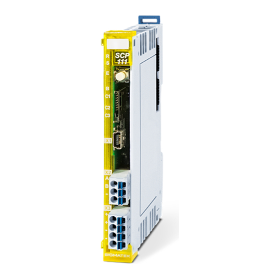
- Page 3 SCP 111-2 S-DIAS Safety CPU Module SCP 111-2 The S-DIAS Safety CPU module SCP 111-2 supports up to 16 Safe IO modules. In addition, the SCP 111-2 can operate handheld devices with Emergency Stop and/or confirmation switches. The Safety CPU component series complies with the SIL3 or SIL CL 3 (EN / IEC 62061) or Performancelevel e (PL e) (EN ISO 13849-1/-2).
-
Page 4: Table Of Contents
SCP 111-2 S-DIAS SAFETY CPU MODULE Table of Contents Basic Safety Guidelines ............5 General Safety Information ............5 Additional Safety Guidelines ............6 General Requirements ..............7 Safety Conformity ..............9 Functional Safety Standards ............9 EU Conformity Declaration ............9 Safety-relevant Parameters ............ - Page 5 S-DIAS SAFETY CPU-MODULE SCP 111-2 Label Field ................... 20 Validation Button ..............21 Explanation of the Individual Sequences ......... 21 6.1.1 Start Sequence ................. 21 6.1.2 Command Selection Sequence ............22 6.1.3 End Sequence .................. 22 6.1.4 Error Sequence ................. 23 Overview of Commands .............
- Page 6 SCP 111-2 S-DIAS SAFETY CPU MODULE 11 Disposal ..................34 12 SCP111 Hardware Class for the SCP 111-2 ......35 12.1 General ..................36 12.2 Safety ................... 37 12.3 Communication Interfaces ............39 12.4 Global Methods ................40 12.4.1 FetchDiagState .................. 40 12.4.2...
-
Page 7: Basic Safety Guidelines
S-DIAS SAFETY CPU-MODULE SCP 111-2 Basic Safety Guidelines General Safety Information If the Safety guidelines are not followed, danger to personnel can result, which could then lead to serious injury or in worst cases, death. In less serious cases, systems and equipment can be damaged. -
Page 8: Additional Safety Guidelines
SCP 111-2 S-DIAS SAFETY CPU MODULE Additional Safety Guidelines Warning, dangerous electrical voltage Attention, tension électrique dangereuse Hot surface warning Avertissement d’une surface chaude Danger for ESD-sensitive components. Les signes de danger pour les composants sensibles aux décharges électrostatiques. This... -
Page 9: General Requirements
Before handling the product to which this documentation Guidelines belongs, the operating instructions and safety guidelines must be read. SIGMATEK GmbH & Co KG accepts no liability for damages resulting from non-compliance with the Safety guidelines or the applicable regulations. - Page 10 SCP 111-2 S-DIAS SAFETY CPU MODULE Designated Use The Safety modules are designed for use in safety-oriented applications and meet the required conditions for safe operation in compliance with Performancelevel e (PL e), in accordance with EN ISO 13849-1/-2 and SIL3 or SIL CL 3 in accordance with EN 62061.
-
Page 11: Safety Conformity
2014/30/EU “Electromagnetic Compatibility” (EMC guideline) • 2011/65/EU “Restricted use of certain hazardous substances in electrical and electronic equipment” (RoHS Guideline) The EU Conformity Declarations are provided on the SIGMATEK website. Using the search function with the keyword “EU Declaration of Conformity”. 08.09.2022 Page 9... -
Page 12: Safety-Relevant Parameters
SFF = 99 % Assembly: Two-channel redundant (diverse) Compatibility The safety-related component, SCP 111-2, is supported with Firmware version V465 or Build No. 1348 and higher of the Safety Designer. Compatibility For compatibility of the S-DIAS Safety modules, see section "Compatibility of S-DIAS Safety Modules"... -
Page 13: Technical Data
S-DIAS SAFETY CPU-MODULE SCP 111-2 Technical Data Performance Data ARM Cortex M µController Addressable Safety I/O modules S-DIAS Safety Bus: 16 data memory type SRAM memory 24 kbytes Program memory type FLASH memory 224 kbytes Remnant memory for parameter lists... -
Page 14: Electrical Requirements
SCP 111-2 S-DIAS SAFETY CPU MODULE Electrical Requirements 3.2.1 Module Supply (Input) Supply voltage +19.2-28.8 V DC, typically +24 V DC UL: Class 2 or LVLC Current consumption, internal typically 95 mA (internal demand) usage (2) (3) maximum 1.4 A... -
Page 15: S-Dias-Bus-/Safety Supply (Output)
800 mA. The total current of the +12 V supply cannot exceed 800 mA. If the SCP 111-2 with a firmware version lower than V431 or with a safety number lower than S01.03.01 is integrated with safety I/O modules in the S-DIAS system (blue... - Page 16 SCP 111-2 S-DIAS SAFETY CPU MODULE Page 14 08.09.2022...
-
Page 17: Miscellaneous
S-DIAS SAFETY CPU-MODULE SCP 111-2 Miscellaneous Article number 20-890-111-2 Approvals , CE, TÜV-Austria EG Type Tested, UL in preparation Environmental Conditions Storage temperature -20 ... +85°C Environmental temperature 0 ... +55°C Humidity 0-95 %, non-condensing Installation altitude above sea 0-2000 m without derating level >... -
Page 18: Mechanical Dimensions
SCP 111-2 S-DIAS SAFETY CPU MODULE Mechanical Dimensions Page 16 08.09.2022... -
Page 19: Connector Layout
S-DIAS SAFETY CPU-MODULE SCP 111-2 Connector Layout The connection of the +24 V supply (X3: Pin 1 and Pin 2) or the GND supply (X3: Pin 3 and Pin 4) are bridged internally. To power the module, only one connection to a +24 V pin (pin 1 or pin 2) and a GND pin (pin 3 or pin 4) is required. -
Page 20: Status Leds
SCP 111-2 S-DIAS SAFETY CPU MODULE Status LEDs The LED display lights continuously to indicate that the in- and outputs are active. green Indicates The time-limited (LED "S" on) or unlimited time ("ST" LED off) operation mode Module yellow STATUS... -
Page 21: Applicable Connectors
S-DIAS SAFETY CPU-MODULE SCP 111-2 Applicable Connectors Connectors: X1: USB Type Mini-B (not included with delivery) X2, X3: Connectors with spring terminals (included with delivery) The spring terminals are suitable for the connection of ultrasonically compressed (ultrasonically welded) strands. Connections:... -
Page 22: Label Field
SCP 111-2 S-DIAS SAFETY CPU MODULE Label Field Manufacturer Weidmüller Type MF 10/5 CABUR MC NE WS Article number Weidmüller 1854510000 Compatible printer Weidmüller Type Printjet Advanced 230V Article number Weidmüller 1324380000 Page 20 08.09.2022... -
Page 23: Validation Button
S-DIAS SAFETY CPU-MODULE SCP 111-2 Validation Button With the validation button S1, several commands as well as the validation can be executed: • Acknowledging an error and exiting the error status • Deleting a configuration in the Safety CPU •... -
Page 24: Command Selection Sequence
SCP 111-2 S-DIAS SAFETY CPU MODULE 6.1.2 Command Selection Sequence After the Start sequence, the desired command is selected. This selection is made with button presses in the following time intervals: The minimum press duration is 200 ms, maximum is approximately 3 seconds;... -
Page 25: Error Sequence
S-DIAS SAFETY CPU-MODULE SCP 111-2 6.1.4 Error Sequence If an invalid button press occurs, as in the sequences described above, the Error sequence is initiated. LED B indicates this sequence with fast blinking, which lasts for at least 3 seconds. -
Page 26: Overview Of Commands
SCP 111-2 S-DIAS SAFETY CPU MODULE Overview of Commands The number of button presses corresponds to the number of light pulses in LED B during the End sequence. Commands Number of button LED C1 LED C2 LED C3 presses QUIT_ERROR... - Page 27 S-DIAS SAFETY CPU-MODULE SCP 111-2 Executed Command Function Status after Command Command Execution QUIT_ERROR A possible error is canceled in the Safety CPU SW-RESET *) and all safety modules required by the Safety CPU and the error status is ended.
-
Page 28: Handling The Microsd Card
SCP 111-2 S-DIAS SAFETY CPU MODULE Handling the microSD Card An SD card can only be written to using the Safety Designer. A detailed description can be found Safety System Handbook (Link: https://www.sigmatek- automation.com/fileadmin/user_upload/downloads/Safety-Systemhandbuch.pdf). A Safety project, which was programmed with the SafetyDesigner, can be stored on an SD card. -
Page 29: Configuring A Safety Cpu Via The Sd Card
Only microSD cards that support version 2.0 or higher of the "SDA Physical Layer Specification" (SDA=SD Card Association) can be used. It is recommended that only microSD cards provided by SIGMATEK be used. The number of read and write actions have a significant influence on the lifespan of the storage media. -
Page 30: Error Response
SCP 111-2 S-DIAS SAFETY CPU MODULE Error Response In the event of an error, please consult the chapter "LED Displays", as important information on the runtime status of the system can be derived from the status of an error display. Since errors in general are of a complex nature, do not perform a diagnosis based on the LEDs alone (consult the corresponding chapter in the Safety System Handbook as well). -
Page 31: Configuration Distribution Error
S-DIAS SAFETY CPU-MODULE SCP 111-2 During restart, the Safety CPU first runs the POST (Power On Self Test). In the POST, whether the Safety CPU is configured or not is determined. If the Flash memory in the Safety CPU is empty, it changes to the service mode and switches the status LED (ST) to continuously on. -
Page 32: Troubleshooting
SCP 111-2 S-DIAS SAFETY CPU MODULE Troubleshooting • Check all modules in the system for completeness and type conformity • Check that all modules are error-free • Check all connector cables • Cancel the error with the QUIT_ERROR command If the Safety CPU remains in the error status after the QUIT_ERROR command has been run, it must be retested using the Safety Designer. -
Page 33: Wiring Instructions
S-DIAS SAFETY CPU-MODULE SCP 111-2 Wiring Instructions The input filters, which suppress noise signals, allow operation in harsh environmental conditions. A careful wiring method is also recommended to ensure error-free function. The following installation instructions must be observed: • Avoid parallel connections between input lines and load-bearing circuits. -
Page 34: Mounting
SCP 111-2 S-DIAS SAFETY CPU MODULE Mounting The S-DIAS modules are designed for installation into the control cabinet. To mount the modules, a DIN-rail is required. The DIN rail must establish a conductive connection with the back wall of the control cabinet. The individual S-DIAS modules are mounted on the DIN rail as a block and secured with latches. - Page 35 S-DIAS SAFETY CPU-MODULE SCP 111-2 Recommended minimum distances between the S-DIAS modules and the surrounding components or control cabinet wall: a, b, c … distances in mm (inches) 08.09.2022 Page 33...
-
Page 36: Supported Cycle Times
SCP 111-2 S-DIAS SAFETY CPU MODULE 10 Supported Cycle Times 10.1 Cycle Times Below 1 ms (in µs) x= supported 10.2 Cycle Times of 1 ms or Greater (in ms) x= supported x= supported 11 Disposal To dispose of the product, the applicable local guidelines must be met and followed. -
Page 37: Scp111 Hardware Class For The Scp 111-2
S-DIAS SAFETY CPU-MODULE SCP 111-2 12 SCP111 Hardware Class for the SCP 111-2 SCP111 hardware class for the S-DIAS SCP 111 Safety CPU Module This hardware class is used to control the SCP 111-2 hardware module. 08.09.2022 Page 35... -
Page 38: General
SCP 111-2 S-DIAS SAFETY CPU MODULE 12.1 General ClassState State This server shows the actual status of the hardware class. DeviceID State This server shows the device ID of the hardware module. FPGAVersion State FPGA version of the module in 16#XY (e.g. 16#10 = version 1.0). -
Page 39: Safety
_AsyncComError Several sequential asynchronous commands failed. Please contact Sigmatek support _DOsIncreasedRestartAp The number or sized of the module access was increased with a new Safety project. => The application must be restarted, because the new data is not covered by the current access. - Page 40 If the safety.dlm is used, the dlm can also cancel other errors starting with Errors version 6(Error server = 1). The Safety dlm be acquired from SIGMATEK Support. For the Salamander operating system, no dlm is required here. Canceling can activate Safety outputs and thereby lead to unexpected responses from machine elements.
-
Page 41: Communication Interfaces
S-DIAS SAFETY CPU-MODULE SCP 111-2 Fast Unsafe Input Bit field with 32 non-Safe outputs. These inputs are configured in the Safety Outputs Designer. More information can be found in the Safety Designer documentation. The hardware class SCPFastUnsafeOutput can be connected so that the bit field can be broken down into individual servers. -
Page 42: Global Methods
SCP 111-2 S-DIAS SAFETY CPU MODULE 12.4 Global Methods 12.4.1 FetchDiagState This method is used to read the diagnostic status information (Run State, Config State, Login Level, Error Counter IO State) from The Safety CPU. 12.4.2 GetDiagState This method is used to retrieve the read diagnostic information of the class. -
Page 43: Savelog
SCP 111-2 12.4.5 SaveLog This method can be used to store the log file from one of the two micro controllers This is a binary file and should be sent to Sigmatek support when an error occurs) Input Parameters Type Description... -
Page 44: Meaning Of Classstate And Safetystate
SCP 111-2 S-DIAS SAFETY CPU MODULE 12.5 Meaning of ClassState and SafetyState The “ClassState” status refers to the SDIAS bus. If “ClassState” shows a status unlike “_ClassOk”, the module on the SDIAS bus cannot be reached. The “SafetyState” status refers to the Safety CPU. If “SafetyState” shows a status unlike “_SafteyClassOK”, the Safety CPU and subsequently, the connected safety modules will not... -
Page 45: Transmission Of Safe Signals Via Multiple Machines Of Machine Components
S-DIAS SAFETY CPU-MODULE SCP 111-2 12.7 Transmission of Safe Signals via Multiple Machines of Machine Components There are several options for exchanging safe signals between different PLCs via the SCP111-2. Depending on the topology, they differ as follows: • Connection via VBC021 (requires a VaranManager on both PLCs) •... -
Page 46: When To Use An Interface Connection Or Flexcon
SCP 111-2 S-DIAS SAFETY CPU MODULE • Connection via UDP (requires an Ethernet interface on both PLCs) Depending on the transmission process or connection management, a further distinction is made: • Interface connections (connection via VBC021, VMC052 or UDP) • FlexCon = Flexible Constellation = Safety Hot Swap (connection via VBC021 or VMC052) 12.7.1... -
Page 47: Interface Connection
S-DIAS SAFETY CPU-MODULE SCP 111-2 12.7.2 Interface Connection 12.7.2.1 Presetting for an Interface Connection In the SafetyDesigner, different ranges of FSoE slave addresses and connection IDs must be set for all projects containing PLCs that communicate with each other (1001 to 2000 in the example). - Page 48 SCP 111-2 S-DIAS SAFETY CPU MODULE After creating the writing interface, it must be exported so that it can be imported to the receiving side as a reading interface. Page 46 08.09.2022...
- Page 49 S-DIAS SAFETY CPU-MODULE SCP 111-2 On the reading side, whether the interface is optional and from where the data is received must be selected. 08.09.2022 Page 47...
- Page 50 SCP 111-2 S-DIAS SAFETY CPU MODULE If the safe signals should now also be transported in the other direction, the process must be repeated in reverse order. Furthermore, as soon as there is a change on the writing side (addition or removal of a variable, name or data type of a variable, use of the connection ID...
- Page 51 S-DIAS SAFETY CPU-MODULE SCP 111-2 To enable safe communication via VBC021 or VMC052 in the LASAL projects, a memory area in bytes must be reserved in the respective objects (VBC021_Master/VBC021_Slave or VMC052/VaranManager_2) for isochronous (PDOs) and asynchronous transmission (SDOs). If VMC052 is used, the VaranManager_2 of the secondary system must also be set for use as a client and the VARAN cycle time of the primary system must be set.
-
Page 52: Safety Hot Swap (Flexcon Connection)
SCP 111-2 S-DIAS SAFETY CPU MODULE 12.7.3 Safety Hot Swap (FlexCon Connection) For this function, a firmware version of at least v453 is required in all connected SCP111-2 modules. For this option, a FlexConHost is available and one or multiple FlexConNodes. Each PLC can thereby assume one of the two roles. - Page 53 S-DIAS SAFETY CPU-MODULE SCP 111-2 None of the nodes in this example could take on the FlexConHost role. Here it must be noted (as with optional interface connections) that in LASAL, a timeout is set for connections not required for operating the machine after the connection setup to external safe stations is terminated.
- Page 54 SCP 111-2 S-DIAS SAFETY CPU MODULE To activate the FlexCon function in the SafetyDesigner project, the “Enable MULTI MODULE” option in the PLC must first be activated. The FlexConHost or FlexConNode module can then be added depending on the configuration.
- Page 55 S-DIAS SAFETY CPU-MODULE SCP 111-2 Here, (in contrast to the read interface connections, where you have to specify either the module or the IP address of the source on the read side) neither the host nor the node has to specify exactly how the connection is established.
- Page 56 SCP 111-2 S-DIAS SAFETY CPU MODULE hardware of the individual nodes may very well differ as needed, as long as the corresponding meaning of the individual signals in the communication structure matches. Due to the requirement of the machine standard, it must be possible to distinguish between active and inactive emergency stop switches.
- Page 57 S-DIAS SAFETY CPU-MODULE SCP 111-2 Documentation Changes Change date Affected page(s) Chapter Note 08.09.2022 Page 55...
Need help?
Do you have a question about the SCP 111-2 and is the answer not in the manual?
Questions and answers