Table of Contents
Advertisement
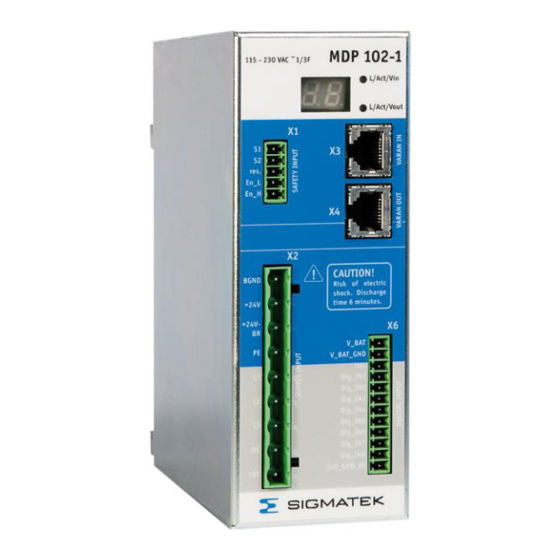
MDP 102-1
Power Supply Module 230 V
MDP 102-1
1 Overview
The MDP 102-1 is a supply module that has a 2 kVA rating
with an input voltage of 230 V. The supply module is de-
signed for the 1-phase connection, with an input voltage of
115 V, it can be powered with a 3-phase connection.
It is fully integrated in the Lasal operating system and has 1
to 8 servo axes. The MDP 102 supply module is a 1-phase
system.
Four axis modules are available, two single-axis modules
for 230 V and 400 V and two dual-axes module for 230 V
and 400 V, which have a scalable output current range of
the 2 axes.
The supply module and the axes modules are put on a
module carrier, which is mounted on the mounting plate of
the cabinet.
The current, speed, and position control of the up to 8 axes
work with a cycle time of 62.5 µs. MDD 100 has a high
flexibility in connection of various feedback systems.
VARAN connects the servo drive system to the machine
controller.
Integrated safety functions "Safe Torque off" STO and "Safe Stop 1" SS1 with a high safety
level ease the integration into the safety concept of the machine.
29.08.2019
Page 1
Advertisement
Table of Contents

Related Manuals for SIGMATEK MDP 102-1


Summary of Contents for SIGMATEK MDP 102-1
-
Page 1: Overview
Power Supply Module 230 V MDP 102-1 1 Overview The MDP 102-1 is a supply module that has a 2 kVA rating with an input voltage of 230 V. The supply module is de- signed for the 1-phase connection, with an input voltage of 115 V, it can be powered with a 3-phase connection. -
Page 2: Table Of Contents
3.3.5 Wire sizing ....................33 3.3.6 External Fusing ..................34 3.3.7 MDP 102-1 Mains Supply Options ............35 3.3.8 Usage of cooling units ................36 3.3.9 Turn on/off response of the servo amplifier ..........38 3.3.10 Holding brake control ................39 4 Safety Function ................ - Page 3 MDP 102-1 Auxiliary 24 V and Holding Brake supply (X2) ......53 DC-link (X2) ................54 Motor connector (X11, X21) ............55 5.4.1 Standard configuration ................55 4.4.2 Classic emergency stop function (stop category 0) ......... 56 4.4.3 Personnel safe holding brake control ............57 Feedback (X12, X22) ..............
-
Page 4: Components Of A Servo System
MDP 102-1 1.1 Components of a servo system Page 4 29.08.2019... -
Page 5: General
MDP 102-1 2 General 2.1 About this manual The manual describes the MDP 102-1 power supply module 230 V. The information provided is: • Technical Data for the power supply module 230 V • Description of the safety function •... -
Page 6: Symbols Used In This Manual
MDP 102-1 2.2 Symbols used in this manual Danger! Shock current Danger to personnel from electricity Caution! General General warning, see document Caution! Hot surface Hot surface more than 80 °C (176 °F) Important note See document Page 6 29.08.2019... -
Page 7: Safety Instructions
MDP 102-1 2.3 Safety Instructions The safety instructions must be read before installation and set-up of the servo drive system, to prevent injury or material damage. It is fun- damental that the technical data and information for connection re- quirements be followed (on the nameplate and in the documentation). - Page 8 MDP 102-1 Annotations Danger! Shock current Wait at least 7 minutes after disconnecting the servo drive system from the mains supply voltage before touching live sections of the equipment (e.g. contacts) or undoing connections. Capacitors can still have dangerous volt- ages levels for up to 7 minutes after switching off the supply voltages.
- Page 9 MDP 102-1 The +24 V auxiliary power supply and also the power supply for the +24 V- BR holding brake supply must be galvanically isolated with SELV output volt- age according to EN 60950. Failure to observe these precautions can result in severe injury and equipment damage.
-
Page 10: Prescribed Use
MDP 102-1 2.4 Prescribed use The safety module "Safe Restart Lock" in an integral component of the DIAS Drive MDP 102-1 and is already installed with delivery; it meets the conditions required for safe opera- tion according to SIL 3 in compliance with IEC 62061 and according to PL e in compliance with EN 13849-1. - Page 11 MDP 102-1 The servo amplifier from SIGMATEK GmbH & Co KG was designed and produced with state of the art technology. Before delivery, the products are completely tested for reliability. It is a built-in component for electrical systems, which can only be operated as an integral part of such systems.
-
Page 12: Non-Prescribed Use
MDP 102-1 2.5 Non-prescribed use “Prescribed use” means, that the servo drive system is used according to the environmental conditions described in this documentation. • It must not be used in electrical equipment on ships (service afloat) or in offshore applications because of the conductive pollution. -
Page 13: Nameplate
MDP 102-1 2.6 Nameplate 29.08.2019 Page 13... -
Page 14: Block Diagram And Concept
MDP 102-1 2.7 Block Diagram and Concept Block diagram of the Power Supply Module Page 14 29.08.2019... - Page 15 MDP 102-1 Module Axis Module Carrier Feedback – Converter Internal coder DC-link +24V-BR Internal Supply 2 x 6 U_Treiber Block diagram of the Axis Module 29.08.2019 Page 15...
- Page 16 MDP 102-1 Hardware • Mains input is fed to the power rectifier, the input filter and the inrush circuit • DC-link connection for connecting the DC-link to other drives for power distribution • Regen unit with internal regen resistor. •...
- Page 17 MDP 102-1 Concept of the MDD 100 • Servo drive system contains of different components - Power supply module for up to eight logical axes - Axis module in different configurations - Single axis module - Dual axis module - Module carrier in different configurations for one to 4 axis modules •...
- Page 18 MDP 102-1 Software functionality • Modified space vector modulation (SVM) technique to reduce the power stage losses • Field oriented current controller (update time 62.5 µs) • Feedback converter and speed controller (update time 62.5 µs) • Spline interpolator and position controller (update time 62.5 µs) •...
-
Page 19: Technical Data Power Supply Module 230 V
MDP 102-1 2.8 Technical Data Power Supply Module 230 V MDP 102-1 Article number 09-403-102-1 Hardware version Rated Data Rated mains voltage (symmetrically to +10% 1 or 3 x 115 V / 1 x 230 V -10% ground) maximum 5000 rms symmetrical... -
Page 20: Safety Conformity
MDP 102-1 Internal fusing Auxiliary supply 24 V (+24 V to BGND) Electronic fuse Holding brake supply 24V-BR (+24 V-BR to BGND) Electronic fuse Regent resistor Electronic protection Resolver specification Exciter frequency f Exciter voltage U 2, 4, 6, .., 32... -
Page 21: Ambient Conditions, Ventilation And Mounting
MDP 102-1 2.10 Ambient conditions, ventilation and mounting page 70 Storage conditions page 70 Transport conditions 0 to +45 °C (32 to 113 °F) at rated data Ambient temperature in operation +45 to 55 °C (113 to 131 °F) with power derating of 2.5 % /... -
Page 22: Installation
MDP 102-1 3 Installation 3.1 Important instructions • If a leakage current sensor is used in the mains supply of the servo drives, a leakage current sensor RCD type B has to be used in any case. If a RCD type A or AC is used, there is a risk, that the DC ground current of the servo drive inhibits the leakage current sensor. - Page 23 MDP 102-1 b) Variable machine mains supply connection: Mains connection with industry connector according to EN 60309 and a minimum wire cross section of the protective conductor of 2.5 mm² (AWG 13) as part of a multi-conductor supply cable. Use an adequate pull relief.
-
Page 24: Important Instructions For The Safety Function
MDP 102-1 3.2 Important instructions for the Safety Function • All control components (switches, relays, PLC, etc.) and the control cabinet must comply with the requirements of the ISO 13849. This in- cludes: – Door – switches, etc. with protection class IP54 as minimum –... - Page 25 MDP 102-1 • If the safety function SS1 (Safe Stop 1) is used, the minimum switch-off time is 0.4 s. Following actions which need the safety function STO (Safe Torque off) e.g. manual- ly engagement into the machine, must not be released before 1 s •...
-
Page 26: Planning Of The Switchgear Cabinet
MDP 102-1 3.3 Planning of the switchgear cabinet 3.3.1 Connection diagram and pin assignment of power supply module Page 26 29.08.2019... - Page 27 MDP 102-1 29.08.2019 Page 27...
- Page 28 MDP 102-1 Connector layout of X1, X2, X3, X4 and X6 Page 28 29.08.2019...
-
Page 29: Ground
MDP 102-1 3.3.2 Ground On the MDD module a mounting bracket is found, which serves as stress relief as well as shielding. Here, the cable shield is connected. 29.08.2019 Page 29... - Page 30 MDP 102-1 The entire MDD System is grounded over the module carrier in the control cabinet. Page 30 29.08.2019...
-
Page 31: Mechanical Construction And Mounting
MDP 102-1 3.3.3 Mechanical construction and mounting The mechanical dimensions of the servo drive system above are: depends on the selected module carrier 120 mm for MDM 011 180 mm for MDM 021 240 mm for MDM 031 300 mm for MDM 041 29.08.2019... - Page 32 MDP 102-1 The mechanical dimensions of the module carrier and the fastening on the mounting plate of the cabinet above are: depends on the selected module carrier 100 mm for MDM 011 160 mm for MDM 021 220 mm for MDM 031...
-
Page 33: Connector Properties
MDP 102-1 3.3.4 Connector properties All connections of the servo drive system (except the ground bolt) are plugging style con- nectors. This makes it easier to install the cables and to replace a drive. Never the less it also opens the possibility to create cable sets for high volume machines. -
Page 34: External Fusing
MDP 102-1 3.3.6 External Fusing The AC-mains and 24 V – fuses are calculated depending on customer needs. Signal Fuses, time delay AC mains input (L1-L3) Size fuses to the average power, needed by the servo drives, connected to the circuit. -
Page 35: Mdp 102-1 Mains Supply Options
If a RCD type A or AC is used, there is a risk, that the DC ground current of the servo drive will inhibit the leakage current sensor. The power supply module MDP 102-1 is a 230 V – input module Grounded mains... -
Page 36: Usage Of Cooling Units
MDP 102-1 3.3.8 Usage of cooling units The servo drive system operates up to 45 °C (55 °C with power reduction) ambient temper- ature. This means, that there could be a need to use a cooling unit. Note: Principally, the usage of a cooling unit can and will produce condensa- tion water. - Page 37 MDP 102-1 Avoid condensation also by observing the following rules: • Set the set point of the temperature control of the cooling unit mini- mal to the temperature of the factory building. • Use only properly sealed switchgear cabinets to avoid condensation by the moist external air.
-
Page 38: Turn On/Off Response Of The Servo Amplifier
MDP 102-1 3.3.9 Turn on/off response of the servo amplifier The turn on/off response of the servo amplifier is shown below. 24V – Auxiliary supply Max. 15 s Amplifier drive ready “ Main con tact L1, L2, L3 Under voltage Max. -
Page 39: Holding Brake Control
MDP 102-1 3.3.10 Holding brake control +24V_BR Min. 0.2 sec Min. 0.1 sec Enable Speed Setpoint Host Speed Setpoint Emergency ramp internally Brake enable delay time Max. 1 sec Actual Speed Speed threshold Enable internally Brake disable delay time Brake... -
Page 40: Safety Function
MDP 102-1 4 Safety Function The MDD 100 servo drive system supports the safety functions SS1 (Safe Stop 1) and STO (Safe Torque Off), and meets the requirements for Category 4 Performance Level "e" ac- cording to EN ISO 13849-1 and SIL3 according to EN 62061. -
Page 41: Implementation
MDP 102-1 4.1 Implementation The following block diagram gives an overview of the internal switching circuit. REL 01 G 01 OPTO 01 CONTR 01 AMP 01 Super visor Astable Multi- U_Treiber vibrator OPTO 02 Super 0.5s visor AMP 02 Control... -
Page 42: Blocks Amv, Opto 01 And Opto 02
MDP 102-1 4.1.2 Blocks AMV, OPTO 01 and OPTO 02 As long as the AMV block is powered by the IN input block, it generates a pulse with a constant frequency that is transmitted to the sequential electronics through blocks OPTO 01 and OPTO 02. -
Page 43: Function
MDP 102-1 4.2 Function The safety functions in the DIAS Drive are controlled over two digital inputs. The following table shows the status that the ENABLE_L and ENABLE_H inputs must as- sume to enable normal operation or trigger the safety function. - Page 44 MDP 102-1 Controlled shut down (K-EN = 0): If the actual speed reaches < 1% of min(N-NMAX, V-NMAX) or the ramp time exceeds 1 second, the brake is activated and the pre-set speed (I-NCMD) is immediately set to 0 (to support the braking effect).
-
Page 45: Function Test
MDP 102-1 4.3 Function Test The safety function test is required to ensure correct operation. The entire safety circuit must be tested for full functionality. Tests must be performed at the following times: • After installation • In regular intervals, or at least once a year. -
Page 46: Example Connection With Switching Contacts
MDP 102-1 4.4 Example Connection with Switching Contacts To meet the requirements of safety category 4, performance level "e" for EN 13849-1 and SIL3 according to EN 62061, a two-channel control must be provided for the safety func- tions. The wiring for both connections must be provided with protective insulation (to avoid the "external voltage supply"... -
Page 47: Example: Safety Plc Application
MDP 102-1 4.5 Example: Safety PLC Application To meet the requirements of safety category 4, performance level "e" for EN 13849-1 and SIL 3 according to EN 62061, an error-proof output of a safety PLC must be used. There are two Types of error-safe outputs. - Page 48 MDP 102-1 Page 48 29.08.2019...
- Page 49 MDP 102-1 Two-channel error-proof relay output, with which the + output is connected to EN- ABLE_H and the – output to ENABLE_L. 29.08.2019 Page 49...
- Page 50 MDP 102-1 Page 50 29.08.2019...
-
Page 51: Interfaces
( page 36). Note: If the DC-link of two or more MDD 100 systems are linked with the same supply voltage, the mains inputs must also be linked. 1-phase connection of the MDP 102-1 power supply module: Power supply Module Mains contactor 29.08.2019... - Page 52 MDP 102-1 3-phase connection of the MDP 102-1 power supply module: Mains contactor Power supply Module Page 52 29.08.2019...
-
Page 53: Auxiliary 24 V And Holding Brake Supply (X2)
MDP 102-1 5.2 Auxiliary 24 V and Holding Brake supply (X2) Note: Only use power supply with galvanic isolated SELV output voltage! If a 24 V auxiliary power supply is installed in the switchgear cabinet for relays, contactors or other devices, this 24 V can be used to supply also the servo drive (notice the current rating of the power supply). -
Page 54: Dc-Link (X2)
MDP 102-1 5.3 DC-link (X2) When several drives are connected together, the DC-link connection enables power sharing between different axes. Note: If the DC-link of several servo drives is connected together, the mains input must also be connected in parallel to the drives connected of the group. -
Page 55: Motor Connector (X11, X21)
MDP 102-1 5.4 Motor connector (X11, X21) 5.4.1 Standard configuration The motor cable length is limited to 25 m. If a longer motor cable is required, use an addi- tion motor choke in the output of the servo drive. Axis Module... -
Page 56: Classic Emergency Stop Function (Stop Category 0)
MDP 102-1 4.4.2 Classic emergency stop function (stop category 0) The motor cable length is limited to 25 m. If a longer motor cable is required, use an addi- tion motor choke in the output of the servo drive. Note: The contactor K has to be switched on, before the servo drive is en- abled and to be switched off minimal 1ms after disable. -
Page 57: Personnel Safe Holding Brake Control
MDP 102-1 4.4.3 Personnel safe holding brake control The servo drive has a high level of functional safety of the control of the holding brake. If it is necessary to have a personnel-safe control for the holding brake, this requires one or two additional safety contacts in compliance with the safety standards in the +24 V-BR - line. -
Page 58: Feedback (X12, X22)
MDP 102-1 5.5 Feedback (X12, X22) The servo drive has feedback inputs for several different feedback devices. • Resolver Feedback with thermal contact in the motor winding • ® EnDat encoder (single and multiturn) • Hiperface® encoder (single and multiturn) •... -
Page 59: Resolver Feedback
MDP 102-1 5.5.1 Resolver Feedback The standard feedback system for servomotors is resolver feedback. The servo drive allows evaluation of single speed (2-pole) and also multi speed resolvers (up to 32-pole). The maximum cable length is limited to 50 m. -
Page 60: Endat Feedback
MDP 102-1 ® 5.5.2 EnDat Feedback One of the high-resolution feedback systems for servomotors is the encoder with EnDat interface. The maximum cable length is limited to 10 m. If a thermal contact is used in the motor, the signal is also connected via the encoder cable. - Page 61 MDP 102-1 The Maximum cable length is 10 m, with the exception of the following encoders: Type code Motor type Encoder Type Max. Length description AKM2 – AKM3 ECI 1118 8,2 m AKM2 – AKM3 EQI 1130 6,9 m AKM2 – AKM4...
- Page 62 MDP 102-1 Cabel length is halved since the supply and GND line form the entire length. Cable wire Legend: U = Voltage drop ( 5 V supply – minimum encode supply) R = Wire resistance I = Maximum required encoder current ρ...
-
Page 63: Hiperface Feedback
MDP 102-1 ® 5.5.3 Hiperface Feedback ® An encoder with Hiperface interface is a high-resolution interface for servomotors. The maximum cable length is limited to 25 m. If a thermal contact is used in the motor, the sig- nal is also connected via the encoder cable. -
Page 64: Sine Encoder Feedback
MDP 102-1 5.5.4 Sine Encoder Feedback A sine encoder is a high-resolution feedback system, used with linear or torque servomo- tors. The maximum cable length is limited to 10 m. If a thermal contact is used in the motor, the signal is also connected via the encoder cable. -
Page 65: Sanyo Denki Motor
MDP 102-1 5.5.5 Sanyo Denki Motor A Sanyo Denki motor with an absolute encoder with no battery can be connected to the MDD 100. The maximum cable length is limited to 25 m. The battery type is in preparation. Sanyo Denki Motor, R Series... -
Page 66: Panasonic Feedback
MDP 102-1 5.5.6 Panasonic Feedback The Panasonic feedback analysis is supported starting with FW version 1.84 in combination with the MDD FPGA version v22 (see parameter I-HC). The maximum cable length is 25 m. Page 66 29.08.2019... -
Page 67: Biss C Feedback
MDP 102-1 5.5.7 BiSS C Feedback The BiSS C analysis is supported starting with FW version 1.84 in combination with the MDD FPGA version v22 (see parameter I-HC). The maximum cable length is 10 m. If a thermos contact is used the signal is wired via the feedback cable. -
Page 68: Maintenance
MDP 102-1 6 Maintenance The servo drive does not require any maintenance. Note: Opening the enclosure invalidates the warranty If the casing is dirty, clean with Isopropanol or similar cleaning agent. • Dirt inside the unit must be cleaned by the manufacturer •... - Page 69 MDP 102-1 Disassemble the servo drive. Check the replacement component and compare it to the disassembled one. Install only the same type! Plug the connectors. Be careful not to swap connectors. Install the fuses supplying the servo drive system, switch on the main switch of the switchgear cabinet.
-
Page 70: Appendix
MDP 102-1 7 Appendix 7.1 Transport, storage and disposal Transport: • Use only the manufacturer’s original recyclable packaging • Avoid shocks • Maximum temperature range –25 to +70 °C (-13...158 °F), maximum 20 K/h rate of change • Maximum 95 % relative humidity, not condensing •... - Page 71 MDP 102-1 • Storage duration: < 1 year: without restriction ≥ 1 year: capacitors must be re-formed before operating the ser- vo drive. To re-form, remove all electrical connections, and supply the servo amplifier for about 30 min. from 230 VAC, single-phase, on terminals L1 / L2.
-
Page 72: Troubleshooting And Fault Elimination
MDP 102-1 7.2 Troubleshooting and Fault Elimination Faults and warnings can be detected by LED and bus system. The list “Status Register” helps you eliminate the errors. 7.2.1 Seven segment display Display Description 8.8. Initialization of the display During start-up the FPGA version is shown... -
Page 73: Malfunction Of The Drive
MDP 102-1 7.2.3 Malfunction of the drive Malfunction of the drive Cause Remedy ─ I-FPOS shows decrementing ─ Feedback system is not ─ Connect feedback system according values when the motor ro- connected correctly to drawing tates clockwise (view of the... -
Page 74: Status Register
MDP 102-1 7.2.4 Status Register The MDD 100 has a status register, read by I-STATUS. It is a 32-Bit variable that contains all error and status information. The internal behavior of the drive to the different bits can be set by G-MASKE1, G-MASKE2, G-MASKW and G-MASKD. According to the setting of the different masks, the drive detects an error, warning or does not react at all. - Page 75 MDP 102-1 ─ internal temperature too ─ improve ventilation in the cabi- Ambient tempera- ture high net and check mounting posi- tion according to this manual ─ heat sink temperature too ─ improve ventilation in the cabi- Heat sink tempera-...
- Page 76 MDP 102-1 Power stage fault: ─ motor cable has (ground) ─ replace motor cable short circuit ─ motor has (ground) short ─ replace motor circuit ─ power stage is damaged ─ replace drive Regen fault: ─ regen resistor has ─ replace module rack (ground) short circuit ─...
- Page 77 MDP 102-1 ─ When the sum output ─ Servo drive system meets not Max. Sum Power Limitation power of all axes exceeds the demands of the Application the power supply limitation reserved ─ The fan does not reach the ─ Exchange axis module.
-
Page 78: Varan Recommended Shielding
It is recommended that whenever possible, to avoid wiring VARAN-Bus lines parallel to power cables. SIGMATEK recommends the use of CAT5e industrial Ethernet bus lines. For the shielding variants, an S-FTP bus line is recommended, which is a symmetric, multi- wire cable with unshielded pairs. -
Page 79: Wiring From The Control Cabinet To An External Varan Component
MDP 102-1 8.1 Wiring from the Control Cabinet to an External VARAN Component If the Ethernet lines are connected from a VARAN component to a VARAN node outside the control cabinet, the shielding should be placed at the entry point to the control cabinet housing. -
Page 80: Wiring Outside Of The Control Cabinet
MDP 102-1 8.2 Wiring Outside of the Control Cabinet If a VARAN bus cable must be placed outside of the control cabinet only, no additional shield connection is required. This requires that only IP67 modules and connectors be used. These components are very robust and noise resistant. The shielding for all sockets in IP67 modules are internally connected to common bus or electrically connected to the housing, whereby the deflection of voltage spikes does not flow through the electronics. -
Page 81: Shielding For Wiring Within The Control Cabinet
MDP 102-1 8.3 Shielding for Wiring Within the Control Cabinet Sources of strong electromagnetic noise located within the control cabinet (drives, Trans- formers, etc.) can induce interference in a VARAN bus line. Spike voltages are deflected over the metallic housing of a RJ45 connector. Noise is conducted through the control cabi-... -
Page 82: Connecting Noise-Generating Components
MDP 102-1 8.4 Connecting Noise-Generating Components With the connection of power components that generate strong electromagnetic noise, it is also critical to ensure correct shielding. The shielding should be placed before a power component (or a group thereof). Page 82... -
Page 83: Shielding Between Two Control Cabinets
MDP 102-1 8.5 Shielding Between Two Control Cabinets If two control cabinets must be connected over a VARAN bus, it is recommended that the shielding be located at the entry points to both cabinets. Noise can thereby be kept from reaching the electronics within the control cabinet. - Page 84 MDP 102-1 Page 84 29.08.2019...
Need help?
Do you have a question about the MDP 102-1 and is the answer not in the manual?
Questions and answers