Table of Contents
Advertisement
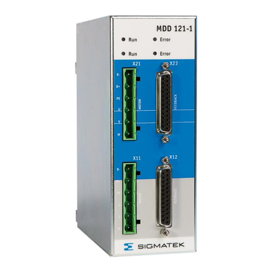
MDD 121-1
Axis Module 400 V/480 V
MDD 121-1
1 Overview
The MDD 121-1 is an axis module for two axes with a
continuous sum current of 6 A at 230 V and 4 A at 400/480 V
and
a
peak
current
of
18
A
at
230
V
and
12 A at 400/480 V.
MDD 100 is a small to midsize power range servo drive
system, especially developed for multi-axial applications in
the low, middle and high performance range.
It is fully integrated in the LASAL operating system and has 1
to 8 servo axes.
Depending on the supply module used and the motor type,
the system is a 1-phase 230 VAC or a 3-phase 400-480 VAC
system.
Four axis modules are available, two single-axis modules for
230 V and 400 V and two dual-axes module for 230 V and
400 V, which have a scalable output current range of the 2
axes.
The supply module and the axes modules are put on a
module carrier, which is mounted on the mounting plate of the cabinet.
The current, speed, and position control of the up to 8 axes work with a cycle time
of 62.5 µs. MDD 100 has a high flexibility in connection of various feedback systems.
VARAN connects the servo drive system to the machine controller.
Integrated safety functions "Safe Torque off" STO and "Safe Stop 1" SS1 with a high safety
level ease the integration into the safety concept of the machine.
10.03.2021
Page 1
Advertisement
Table of Contents

Related Manuals for SIGMATEK MDD 121-1


Summary of Contents for SIGMATEK MDD 121-1
-
Page 1: Overview
MDD 121-1 Axis Module 400 V/480 V MDD 121-1 1 Overview The MDD 121-1 is an axis module for two axes with a continuous sum current of 6 A at 230 V and 4 A at 400/480 V peak current 12 A at 400/480 V. -
Page 2: Table Of Contents
MDD 121-1 1 Overview ..................1 Components of a servo system ........... 4 2 General ..................5 About this manual ............... 5 Symbols used in this manual............6 Safety Instructions ..............7 Conformity with European Directives ........10 Prescribed use ................11 Non-prescribed use .............. - Page 3 MDD 121-1 4.4.3 Personnel safe holding brake control ............. 48 Feedback (X12, X22) ..............49 5.2.1 Resolver Feedback ................50 ® 5.2.2 EnDat Feedback .................. 51 ® 5.2.3 Hiperface Feedback ................54 5.2.4 Sine Encoder Feedback ................ 55 5.2.5 Sanyo Denki Motor ................56 5.2.6...
-
Page 4: Components Of A Servo System
MDD 121-1 1.1 Components of a servo system Page 4 10.03.2021... -
Page 5: General
MDD 121-1 2 General 2.1 About this manual The manual describes the MDD 121-1 axis module 400 V/480 V. The information provided is: • Technical Data for the axis module 400 V/480 V • Description of the safety function •... -
Page 6: Symbols Used In This Manual
MDD 121-1 2.2 Symbols used in this manual Danger! Shock current Danger to personnel from electricity Caution! General General warning, see document Caution! Hot surface Hot surface more than 80 °C (176 °F) Important note See document Page 6 10.03.2021... -
Page 7: Safety Instructions
MDD 121-1 2.3 Safety Instructions The safety instructions must be read before installation and set-up of the servo drive system, to prevent injury or material damage. It is fundamental that the technical data and information for connection requirements be followed (on the nameplate and in the documentation). - Page 8 MDD 121-1 Caution General The availability of the servo drive system is limited according to EN61800-3. This product can cause radio interference problems in living quarters. In this case, it may be necessary for the operator to take adequate measures.
- Page 9 MDD 121-1 Caution! Hot surface During operation, the housing of the servo drive can become hot and may reach temperatures above 80 °C (176 °F). Especially the rear side of the module carrier will get hot, if the system is not mounted on a mounting plate in the cabinet.
-
Page 10: Conformity With European Directives
MDD 121-1 2.4 Conformity with European Directives Servo drives are components, which are built into electrical equipment and machines for industrial use. The operation is forbidden, until the machine or plant fulfils the requirements defined by the EC Directive on Machines 2006/42/EC and the Electromagnetic Compatibility (EMC) directive 2014/30/EU. -
Page 11: Prescribed Use
MDD 121-1 2.5 Prescribed use The servo drives of SIGMATEK GmbH & Co KG are developed and produced according to the actual prior art. The products are fully tested before delivery, especially in terms of fail- safe conditions. They are components, which are built into electrical equipment and can only be used as integral components of such equipment. -
Page 12: Non-Prescribed Use
MDD 121-1 • Power supply modules MDP101-1 and MDP 102-1 are to be used with axis modules MDD111-1 and MDD121-1 only. • Drives must to be used with motors provided with over temperature sensing. 2.6 Non-prescribed use “Prescribed use” means, that the servo drive system is used according to the environmental conditions described in this documentation. -
Page 13: Nameplate
MDD 121-1 2.7 Nameplate 10.03.2021 Page 13... -
Page 14: Block Diagram And Concept
MDD 121-1 2.8 Block Diagram and Concept Block diagram of the Power Supply Module Page 14 10.03.2021... - Page 15 MDD 121-1 Module Axis Module Carrier Feedback – Converter Internal coder DC-link +24V-BR Internal Supply 2 x 6 U_Treiber Block diagram of the Axis Module 10.03.2021 Page 15...
- Page 16 MDD 121-1 Hardware • Mains input is fed to the power rectifier, the input filter and the inrush circuit • DC-link connection for connecting the DC-link to other drives for power distribution • Regen unit with internal regen resistor. •...
- Page 17 MDD 121-1 Concept of the MDD 100 • Servo drive system contains of different components - Power supply module for up to eight logical axes - Axis module in different configurations - Single axis module - Dual axis module - Module carrier in different configurations for one to 4 axis modules •...
- Page 18 MDD 121-1 Software functionality • Modified space vector modulation (SVM) technique to reduce the power stage losses • Field oriented current controller (update time 62.5 µs) • Feedback converter and speed controller (update time 62.5 µs) • Spline interpolator and position controller (update time 62.5 µs) •...
-
Page 19: Technical Data Axis Module 400 V/480 V
MDD 121-1 2.9 Technical Data Axis Module 400 V/480 V MDD 121-1 Article number 09-404-121-1 Rated Data Nominal allowed mains voltage 230/ 400 / 480 Max. holding brake current per axis Holding brake voltage drop from Max. 1 (at 1A holding brake current) +24 V-BR to output Max. - Page 20 MDD 121-1 Mechanics Height Width Depth with module carrier (without/with 152/195 plugs) Weight General Article number 09-404-121-1 Standard UL 508C, NMMS.E336350 Is limited to the equivalent continuous sum current depending on axis 2 Is limited to the equivalent peak sum current depending on axis 2 Page 20 10.03.2021...
-
Page 21: Ambient Conditions, Ventilation And Mounting
MDD 121-1 2.10 Ambient conditions, ventilation and mounting page 61 Storage conditions page 61 Transport conditions 0 to +45 °C (32 to 113 °F) at rated data Ambient temperature in operation +45 to 55 °C (113 to 131 °F) with power derating of 2.5 % /... -
Page 22: Installation
MDD 121-1 3 Installation 3.1 Important instructions • If a leakage current sensor is used in the mains supply of the servo drives, a leakage current sensor RCD type B has to be used in any case. If a RCD type A or AC is used, there is a risk, that the DC ground current of the servo drive inhibits the leakage current sensor. -
Page 23: Important Instructions For The Safety Function
MDD 121-1 • Route the motor and control cables separately (distance about 100 mm). This improves the noise level of the control signals because of the high radiation of the motor cables. Use only screened motor and feedback cable with shield connections on both ends. - Page 24 MDD 121-1 • When an external force is likely to act with the function ”safe restart lock” (e.g. force to the load by hanging load) additional measures have to be provided (e.g. double-disc spring set brake, instead of permanent magnetic-excited brake) Failure to observe this precaution can result in severe injury and equipment damage.
-
Page 25: Planning Of The Switchgear Cabinet
MDD 121-1 3.3 Planning of the switchgear cabinet 3.3.1 Connection diagram and pin assignment of the axis module Module Axis Module Carrier Sine Sine encoder encoder Resolver Motor 2 Motor 2 Sine Sine encoder encoder Resolver Resolver Motor 1 Motor 1... - Page 26 MDD 121-1 Page 26 10.03.2021...
-
Page 27: Ground
MDD 121-1 3.3.2 Ground On the MDD module a mounting bracket is found, which serves as stress relief as well as shielding. Here, the cable shield is connected. 10.03.2021 Page 27... - Page 28 MDD 121-1 The entire MDD System is grounded over the module carrier in the control cabinet. Page 28 10.03.2021...
-
Page 29: Mechanical Construction And Mounting
MDD 121-1 3.3.3 Mechanical construction and mounting The mechanical dimensions of the servo drive system above are: depends on the selected module carrier 120 mm for MDM 011 180 mm for MDM 021 240 mm for MDM 031 300 mm for MDM 041 10.03.2021... - Page 30 MDD 121-1 The mechanical dimensions of the module carrier and the fastening on the mounting plate of the cabinet above are: depends on the selected module carrier 100 mm for MDM 011 160 mm for MDM 021 220 mm for MDM 031...
-
Page 31: Connector Properties
MDD 121-1 3.3.4 Connector properties All connections of the servo drive system (except the ground bolt) are plugging style connectors. This makes it easier to install the cables and to replace a drive. Never the less it also opens the possibility to create cable sets for high volume machines. -
Page 32: External Fusing
MDD 121-1 3.3.6 External Fusing The AC-mains and 24 V – fuses are calculated depending on customer needs. Signal Fuses, time delay AC mains input (L1-L3) Size fuses to the average power, needed by the servo drives, connected to the circuit. Maximum rating is 12 A time delay corresponding to cable diameter of 2.5 mm²... -
Page 33: Usage Of Cooling Units
MDD 121-1 3.3.7 Usage of cooling units The servo drive system operates up to 45 °C (55 °C with power reduction) ambient temperature. This means, that there could be a need to use a cooling unit. Note: Principally, the usage of a cooling unit can and will produce condensation water. - Page 34 MDD 121-1 Avoid condensation also by observing the following rules: • Set the set point of the temperature control of the cooling unit minimal to the temperature of the factory building. • Use only properly sealed switchgear cabinets to avoid condensation by the moist external air.
-
Page 35: Turn On/Off Response Of The Servo Amplifier
MDD 121-1 3.3.8 Turn on/off response of the servo amplifier The turn on/off response of the servo amplifier is shown below. 24V – Auxiliary supply Max. 15 s Amplifier drive ready “ Main con tact L1, L2, L3 Under voltage Max. -
Page 36: Holding Brake Control
MDD 121-1 3.3.9 Holding brake control +24V_BR Min. 0.2 sec Min. 0.1 sec Enable Speed Setpoint Host Speed Setpoint Emergency ramp internally Brake enable delay time Max. 1 sec Actual Speed Speed threshold Enable internally Brake disable delay time Brake... -
Page 37: Safety Function
MDD 121-1 4 Safety Function The MDD 100 servo drive system supports the safety functions SS1 (Safe Stop 1) and STO (Safe Torque Off), and meets the requirements for Category 4 Performance Level "e" according to EN ISO 13849-1 and SIL3 according to EN 62061. -
Page 38: Implementation
MDD 121-1 4.1 Implementation The following block diagram gives an overview of the internal switching circuit. REL 01 G 01 OPTO 01 CONTR 01 AMP 01 Super visor Astable Multi- U_Treiber vibrator OPTO 02 Super 0.5s visor AMP 02 Control... -
Page 39: Blocks Amv, Opto 01 And Opto 02
MDD 121-1 4.1.2 Blocks AMV, OPTO 01 and OPTO 02 As long as the AMV block is powered by the IN input block, it generates a pulse with a constant frequency that is transmitted to the sequential electronics through blocks OPTO 01 and OPTO 02. -
Page 40: Function
MDD 121-1 4.2 Function The safety functions in the DIAS Drive are controlled over two digital inputs. The following table shows the status that the ENABLE_L and ENABLE_H inputs must assume to enable normal operation or trigger the safety function. - Page 41 MDD 121-1 Software Enable ENABLE_H – ENABLE_L >= 15V STO aktivated SS1 aktivated Enable (internally) Speed set point of the controller G-EMRAMP Actual speed max. 1 s Timing Diagram If the ENABLE_L and ENABLE_H are changed from any status to the "Drive Ready" status, the servo amplifier is not immediately enabled.
-
Page 42: Function Test
MDD 121-1 4.3 Function Test The safety function test is required to ensure correct operation. The entire safety circuit must be tested for full functionality. Tests must be performed at the following times: • After installation • In regular intervals, or at least once a year. -
Page 43: Example Connection With Switching Contacts
MDD 121-1 4.4 Example Connection with Switching Contacts To meet the requirements of safety category 4, performance level "e" for EN 13849-1 and SIL3 according to EN 62061, a two-channel control must be provided for the safety functions. The wiring for both connections must be provided with protective insulation (to avoid the "external voltage supply"... -
Page 44: Example: Safety Plc Application
MDD 121-1 4.5 Example: Safety PLC Application To meet the requirements of safety category 4, performance level "e" for EN 13849-1 and SIL 3 according to EN 62061, an error-proof output of a safety PLC must be used. There are two Types of error-safe outputs. - Page 45 MDD 121-1 Two-channel error-proof relay output, with which the + output is connected to ENABLE_H and the – output to ENABLE_L. 10.03.2021 Page 45...
-
Page 46: Interfaces
MDD 121-1 5 Interfaces 5.1 Motor connector (X11, X21) 5.1.1 Standard configuration The motor cable length is limited to 20 m. If a longer motor cable is required, use an addition motor choke in the output of the servo drive. -
Page 47: Classic Emergency Stop Function (Stop Category 0)
MDD 121-1 4.4.2 Classic emergency stop function (stop category 0) The motor cable length is limited to 20 m. If a longer motor cable is required, use an addition motor choke in the output of the servo drive. Note: The contactor K has to be switched on, before the servo drive is enabled and to be switched off minimal 1ms after disable. -
Page 48: Personnel Safe Holding Brake Control
MDD 121-1 4.4.3 Personnel safe holding brake control The servo drive has a high level of functional safety of the control of the holding brake. If it is necessary to have a personnel-safe control for the holding brake, this requires one or two additional safety contacts in compliance with the safety standards in the +24 V-BR - line. -
Page 49: Feedback (X12, X22)
MDD 121-1 5.2 Feedback (X12, X22) The servo drive has feedback inputs for several different feedback devices. • Resolver Feedback with thermal contact in the motor winding • ® EnDat encoder (single and multiturn) • Hiperface® encoder (single and multiturn) •... -
Page 50: Resolver Feedback
MDD 121-1 5.2.1 Resolver Feedback The standard feedback system for servomotors is resolver feedback. The servo drive allows evaluation of single speed (2-pole) and also multi speed resolvers (up to 32-pole). The maximum cable length is limited to 50 m. If a thermal contact is used in the motor, the signal is also connected via the resolver cable. -
Page 51: Endat ® Feedback
MDD 121-1 ® 5.2.2 EnDat Feedback One of the high-resolution feedback systems for servomotors is the encoder with EnDat interface. The maximum cable length is limited to 10 m. If a thermal contact is used in the motor, the signal is also connected via the encoder cable. - Page 52 MDD 121-1 The Maximum cable length is 10 m, with the exception of the following encoders: Type code Motor type Encoder Type Max. Length description AKM2 – AKM3 ECI 1118 8,2 m AKM2 – AKM3 EQI 1130 6,9 m AKM2 – AKM4...
- Page 53 MDD 121-1 Cabel length is halved since the supply and GND line form the entire length. Cable wire Legend: U = Voltage drop ( 5 V supply – minimum encode supply) R = Wire resistance I = Maximum required encoder current ρ...
-
Page 54: Hiperface Feedback
MDD 121-1 ® 5.2.3 Hiperface Feedback ® An encoder with Hiperface interface is a high-resolution interface for servomotors. The maximum cable length is limited to 25 m. If a thermal contact is used in the motor, the signal is also connected via the encoder cable. -
Page 55: Sine Encoder Feedback
MDD 121-1 5.2.4 Sine Encoder Feedback A sine encoder is a high-resolution feedback system, used with linear or torque servomotors. The maximum cable length is limited to 10 m. If a thermal contact is used in the motor, the signal is also connected via the encoder cable. -
Page 56: Sanyo Denki Motor
MDD 121-1 5.2.5 Sanyo Denki Motor A Sanyo Denki motor with an absolute encoder with no battery can be connected to the MDD 100. The maximum cable length is limited to 25 m. The battery type is in preparation. Sanyo Denki Motor, R Series... -
Page 57: Panasonic Feedback
MDD 121-1 5.2.6 Panasonic Feedback The Panasonic feedback analysis is supported starting with FW version 1.84 in combination with the MDD FPGA version v22 (see parameter I-HC). The maximum cable length is 25 m. 10.03.2021 Page 57... -
Page 58: Biss C Feedback
MDD 121-1 5.2.7 BiSS C Feedback The BiSS C analysis is supported starting with FW version 1.84 in combination with the MDD FPGA version v22 (see parameter I-HC). The maximum cable length is 10 m. If a thermos contact is used the signal is wired via the feedback cable. -
Page 59: Maintenance
MDD 121-1 6 Maintenance The servo drive does not require any maintenance. Note: Opening the enclosure invalidates the warranty If the casing is dirty, clean with Isopropanol or similar cleaning agent. • Dirt inside the unit must be cleaned by the manufacturer •... - Page 60 MDD 121-1 Disassemble the servo drive. Check the replacement component and compare it to the disassembled one. Install only the same type! Plug the connectors. Be careful not to swap connectors. Install the fuses supplying the servo drive system, switch on the main switch of the switchgear cabinet.
-
Page 61: Appendix
MDD 121-1 7 Appendix 7.1 Transport, storage and disposal Transport: • Use only the manufacturer’s original recyclable packaging • Avoid shocks • Maximum temperature range –25 to +70 °C (-13...158 °F), maximum 20 K/h rate of change • Maximum 95 % relative humidity, not condensing •... - Page 62 MDD 121-1 • Storage duration: < 1 year: without restriction ≥ 1 year: capacitors must be re-formed before operating the servo drive. To re-form, remove all electrical connections, and supply the servo amplifier for about 30 min. from 230 VAC, single-phase, on terminals L1 / L2.
-
Page 63: Troubleshooting And Fault Elimination
MDD 121-1 7.2 Troubleshooting and Fault Elimination Faults and warnings can be detected by LED and bus system. The list “Status Register” helps you eliminate the errors. 6.2.1 LED Indication Each axis module of the MDD 100 servo drive system has two LED’s for each axis, which display the status of the corresponding axis. -
Page 64: Malfunction Of The Drive
MDD 121-1 6.2.2 Malfunction of the drive Malfunction of the drive Cause Remedy ─ I-FPOS shows decrementing ─ Feedback system is not ─ Connect feedback system according values when the motor connected correctly to drawing rotates clockwise (view of the... -
Page 65: Status Register
MDD 121-1 6.2.3 Status Register The MDD 100 has a status register, read by I-STATUS. It is a 32-Bit variable that contains all error and status information. The internal behavior of the drive to the different bits can be set by G-MASKE1, G-MASKE2, G-MASKW and G-MASKD. According to the setting of the different masks, the drive detects an error, warning or does not react at all. - Page 66 MDD 121-1 ─ internal temperature too high ─ improve ventilation in the cabinet Ambient temperature and check mounting position according to this manual ─ heat sink temperature too high ─ improve ventilation in the cabinet, Heat sink temperature check mounting position according to this manual or use a cooling unit ─...
- Page 67 MDD 121-1 Power stage fault: ─ motor cable has (ground) ─ replace motor cable short circuit ─ motor has (ground) short ─ replace motor circuit ─ power stage is damaged ─ replace drive Regen fault: ─ regen resistor has (ground) ─...
-
Page 68: Varan Recommended Shielding
It is recommended that whenever possible, to avoid wiring VARAN-Bus lines parallel to power cables. SIGMATEK recommends the use of CAT5e industrial Ethernet bus lines. For the shielding variants, an S-FTP bus line is recommended, which is a symmetric, multi- wire cable with unshielded pairs. -
Page 69: Wiring From The Control Cabinet To An External Varan Component
MDD 121-1 8.1 Wiring from the Control Cabinet to an External VARAN Component If the Ethernet lines are connected from a VARAN component to a VARAN node outside the control cabinet, the shielding should be placed at the entry point to the control cabinet housing. -
Page 70: Wiring Outside Of The Control Cabinet
MDD 121-1 8.2 Wiring Outside of the Control Cabinet If a VARAN bus cable must be placed outside of the control cabinet only, no additional shield connection is required. This requires that only IP67 modules and connectors be used. These components are very robust and noise resistant. The shielding for all sockets in IP67 modules are internally connected to common bus or electrically connected to the housing, whereby the deflection of voltage spikes does not flow through the electronics. -
Page 71: Shielding For Wiring Within The Control Cabinet
MDD 121-1 8.3 Shielding for Wiring Within the Control Cabinet Sources of strong electromagnetic noise located within the control cabinet (drives, Transformers, etc.) can induce interference in a VARAN bus line. Spike voltages are deflected over the metallic housing of a RJ45 connector. Noise is conducted through the... -
Page 72: Connecting Noise-Generating Components
MDD 121-1 8.4 Connecting Noise-Generating Components With the connection of power components that generate strong electromagnetic noise, it is also critical to ensure correct shielding. The shielding should be placed before a power component (or a group thereof). Page 72... -
Page 73: Shielding Between Two Control Cabinets
MDD 121-1 8.5 Shielding Between Two Control Cabinets If two control cabinets must be connected over a VARAN bus, it is recommended that the shielding be located at the entry points to both cabinets. Noise can thereby be kept from reaching the electronics within the control cabinet. - Page 74 MDD 121-1 Page 74 10.03.2021...
Need help?
Do you have a question about the MDD 121-1 and is the answer not in the manual?
Questions and answers