
Related Manuals for SIGMATEK HMI-Link G2 Device


Summary of Contents for SIGMATEK HMI-Link G2 Device
- Page 1 HMI-Link G2 Device PC 301-E12 Operating Manual Date of creation: 04.06.2020 Version date: 06.08.2020 Article number: 01-310-301-E12-E...
- Page 2 (print, photocopy, microfilm or in any other process) without express permission. We reserve the right to make changes in the content without notice. SIGMATEK GmbH & Co KG is not responsible for technical or printing errors in this handbook and assumes no responsibility for damages that occur through its use.
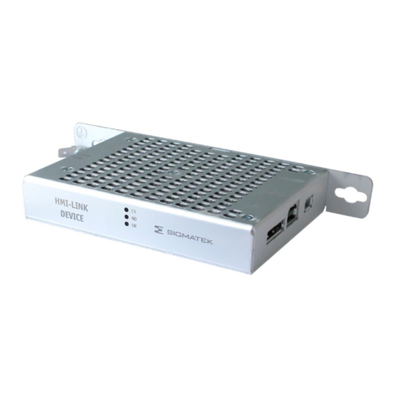
- Page 3 HMI-LINK G2 DEVICE PC 301-E12 HMI-Link G2 Device PC 301-E12 Using HMI-Link G2 Device allows HMI-Link G2 display units to be connected with a SIGMATEK IPC. This allows the transmission of USB and display signals up to 100 m. 06.08.2020 Page 1...
-
Page 4: Table Of Contents
PC 301-E12 HMI-LINK G2 DEVICE Contents Introduction ................5 Target Group/Purpose of this Operating Manual ...... 5 Important Reference Documentation ......... 5 Contents of Delivery ..............5 Basic Safety Guidelines ............6 Symbols Used ................6 Disclaimer ..................8 General Safety Guidelines ............9 Norms and Guidelines ............10... - Page 5 HMI-LINK G2 DEVICE PC 301-E12 X3: HMI Local OUT (HMI-Link G2, Mini-I/O) ......16 X4 Supply voltage ............... 16 6.4.1 Applicable Connectors ..............16 Status Displays ..............17 Assembly/Installation ............18 Check Contents of Delivery ............18 Mounting Instructions ..............18 Installation ...................
- Page 6 PC 301-E12 HMI-LINK G2 DEVICE 12.1 Service ..................26 12.2 Repair ................... 26 13 Disposal ..................27 Page 4 06.08.2020...
-
Page 7: Introduction
Please see our website for our hotline number and business hours. Important Reference Documentation This and additional documents can be downloaded from our website or obtained through SIGMATEK Support. Contents of Delivery 1x HMI-Link G2 Device PC 301-E12 06.08.2020 Page 5... -
Page 8: Basic Safety Guidelines
PC 301-E12 HMI-LINK G2 DEVICE Basic Safety Guidelines Symbols Used The following symbols are used in the operator documentation for warning and danger mes- sages, as well as informational notes: DANGER Danger indicates that death or serious injury will occur, if the specified measures are not taken. - Page 9 HMI-LINK G2 DEVICE PC 301-E12 Danger for ESD-sensitive components. Les signes de danger pour les com- posants sensibles aux décharges électrostatiques. 06.08.2020 Page 7...
-
Page 10: Disclaimer
Please thoroughly read the corresponding documentation and this operating manual before handling a product. SIGMATEK GmbH & Co KG is not liable for damages caused through non-compliance with these instructions or applicable regulations. Page 8... -
Page 11: General Safety Guidelines
Operate the unit with devices and accessories approved by SIGMATEK only. CAUTION Handle the device with care and do not drop or let fall. -
Page 12: Norms And Guidelines
The product was constructed in compliance with the following European Union guidelines and tested for conformity. 3.1.1 EU Declaration of Conformity EU Declaration of Conformity The product HMI-Link G2 Device PC 301 E12 conforms to the following Eu- ropean guidelines: • 2014/35/EG Low-voltage guideline •... -
Page 13: Technical Data
1x HMI Local OUT (HMI-Link G2) Interfaces 1x USB 2.0 (Type B) IN 1x DisplayPort IN In order to use the HMI-Link, a second-generation SIGMATEK HMI-Link (G2) display unit is required on the remote station. Electrical Requirements Supply voltage typically +24 V DC ±20 % (SELV/PELV) Supply voltage (UL) +24 V DC ±20 % (NEC Class 2 or LVLC) -
Page 14: Environmental Conditions
PC 301-E12 HMI-LINK G2 DEVICE Environmental Conditions Storage temperature -20 ... +60°C Environmental temperature 0 ... +50°C Humidity 10-95 %, non-condensing Installation altitude above sea 0-2000 m without derating level > 2000 m up to a maximum of 5000 m with derating of the maximum envi- ronmental temperature by 0.5 °C per 100 m... -
Page 15: Mechanical Dimensions
HMI-LINK G2 DEVICE PC 301-E12 Mechanical Dimensions Dimensions 25 x 204.5 x 83 mm (W x H x D) Material housing: Aluminum anodized Natural C0 Weight 0.20 kg 06.08.2020 Page 13... -
Page 16: Connector Layout
PC 301-E12 HMI-LINK G2 DEVICE Connector Layout bottom Front View Page 14 06.08.2020... -
Page 17: X1: Display Port In
HMI-LINK G2 DEVICE PC 301-E12 X1: Display port IN Function n.c. n.c. n.c. n.c. Lane 1 (n) Lane 1 (p) Lane 0 (n) Lane 0 (p) Config1 Config2 AUX CH (p) AUX CH (n) Hot Plug Return n.c. n.c. = do not use The respective display resolution is transmitted via AUX CH (p) and AUX CH (n) per i2C protocol. -
Page 18: X3: Hmi Local Out (Hmi-Link G2, Mini-I/O)
PC 301-E12 HMI-LINK G2 DEVICE X3: HMI Local OUT (HMI-Link G2, Mini-I/O) Function HMI_P0 HMI_N0 HMI_P1 HMI_P2 HMI_N2 HMI_N1 HMI_P3 HMI_N3 X4 Supply voltage Function +24 V +24 V 6.4.1 Applicable Connectors USB: Type B Display port: 20-pin display port connector HMI-Link: 8-pin Tyco Mini I/O Type 1 Supply voltage Phoenix Contact FK-FMC 1.5/ 4-ST-3.5... -
Page 19: Status Displays
HMI-LINK G2 DEVICE PC 301-E12 Status Displays LED 1 No HMI-Link connection between PC and terminal Check HMI-Link cable LED 2 yellow LED 3 green LED 1 HMI-Link connection between PC and terminal available No video signal available LED 2... -
Page 20: Assembly/Installation
Damaged components can disrupt or damage the system. Mounting Instructions The HMI-Link G2 Device has 2 mounting holes for installation onto the back wall of the control cabinet. This is the preferred mounting position since the cool air can flow from the bottom to the top of the module for optimal cooling. -
Page 21: Installation
HMI-LINK G2 DEVICE PC 301-E12 Installation A different mounting position is not recommended, as the specified environmental tempera- ture cannot be guaranteed. Mounting Material • 2 x M5 screws • 2x M5 washers (EN ISO 7089-5-200HV) 06.08.2020 Page 19... -
Page 22: Minimum Clearance To The Next Components
PC 301-E12 HMI-LINK G2 DEVICE Minimum Clearance to the Next Components Page 20 06.08.2020... -
Page 23: Wiring Guidelines
HMI-LINK G2 DEVICE PC 301-E12 Wiring Guidelines Ground The signal-processing electronics must be connected to ground via the mount on control cabinet or over the ground terminal provided. It is important to create a low-ohm ground con- nection, only then can error-free operation be guaranteed. The ground connection must be made with the maximum cross section and largest (electrical) surface possible. -
Page 24: Shielding
PC 301-E12 HMI-LINK G2 DEVICE Shielding The wiring of all data lines must be shielded. The low-ohm shielding is either connected at the entry to the control cabinet or directly before the device over a large surface (cable grom- mets, grounding clamps)! Noise signals can therefore be prevented from reaching the electronics and affecting the function. -
Page 25: Hmi-Link G2 Wiring
HMI-LINK G2 DEVICE PC 301-E12 10 HMI-Link G2 Wiring 10.1 Shielding The cable shielding must be connected to ground on both sides to prevent noise signals from reaching the electronics and affecting the function. 06.08.2020 Page 23... -
Page 26: Hmi-Link G2 Cable Specification
PC 301-E12 HMI-LINK G2 DEVICE 10.2 HMI-Link G2 Cable Specification For the HMI-Link G2 line, CAT5e or CAT6 cables with shielded connectors must be used. Self-fabricated cables must be tested for compliance with the limit values corresponding to the cable class (CAT5e/CAT6...). -
Page 27: Transport/Storage
HMI-LINK G2 DEVICE PC 301-E12 11 Transport/Storage This device contains sensitive electronics. During transport and storage, high mechanical stress must therefore be avoided. For storage and transport, the same values for humidity and vibration as for operation must be maintained! During transport, temperature and humidity fluctuations may occur. -
Page 28: Maintenance
PC 301-E12 HMI-LINK G2 DEVICE 12 Maintenance During maintenance as well as servicing, observe the safety instructions from chapter 2. 12.1 Service This product was constructed for low-maintenance operation. 12.2 Repair When sent for repair, the panel should be transported in the original packag- ing if possible. - Page 29 HMI-LINK G2 DEVICE PC 301-E12 13 Disposal Should you need to dispose of the device, the national electronic scrap regulation must be observed. The panel cannot be discarded with domestic waste. 06.08.2020 Page 27...
- Page 30 PC 301-E12 HMI-LINK G2 DEVICE Documentation Changes Change date Affected page(s) Chapter Note 06.08.2020 Document General redesign Page 28 06.08.2020...
Need help?
Do you have a question about the HMI-Link G2 Device and is the answer not in the manual?
Questions and answers