Table of Contents
Advertisement
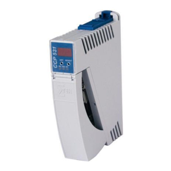
C-DIAS PROCESSOR MODULE
CCP 531
C-DIAS Processor Module
CCP 531
The CCP 531 processor module runs the control program and
thereby represents an essential component of an automation
system. The internal DC/DC converter powers all modules on a
C-DIAS module carrier.
The CAN bus, an Ethernet interface or the USB device (Mini
USB) can be used as the online interface connection.
A 7-segment display and 2 status LEDs provide information on
the actual status of the CPU.
For program updates, the integrated USB Host interface can be
used (USB stick, keyboard). With help from the exchangeable
SD card, the entire control program can be easily exchanged.
The CCP 531 processor module is designed to be mounted in
the control cabinet.
Compatibility
Completely PC-compatible. The CCP 531 works with standard PC BIOS and therefore no
SIGMATEK-specific BIOS is needed; the LASAL operating system in provided.
12.04.2017
Page 1
Advertisement
Table of Contents

Related Manuals for SIGMATEK CCP 531


Summary of Contents for SIGMATEK CCP 531
- Page 1 The CCP 531 processor module is designed to be mounted in the control cabinet. Compatibility Completely PC-compatible. The CCP 531 works with standard PC BIOS and therefore no SIGMATEK-specific BIOS is needed; the LASAL operating system in provided. 12.04.2017 Page 1...
-
Page 2: Technical Data
C-DIAS PROCESSOR MODULE CCP 531 Technical Data Performance data Processor EDGE-Technology X86 compatible 16-bit data bus Clock frequency 500 MHz Addressable I/O/P modules CAN bus: 32 C-DIAS bus: 8 Internal I/O Internal cache 32-kbyte L1 Cache 256-kbyte L2 Cache BIOS... - Page 3 By configuring the packet filter (Firewall or Router) accordingly however, it is possible to connect a network with SIGMATEK hardware to a third party network without trig- gering the error mentioned above.
-
Page 4: Environmental Conditions
C-DIAS PROCESSOR MODULE CCP 531 Miscellaneous Article number 12-104-531 (512 Mbytes microSD card) 12-104-531-1 (1-Gbyte microSD card) Hardware version Project back-up Internally on the microSD card Standard UL508 (E247993) Environmental conditions Storage temperature -10 ... +85 °C Operating temperature 0 ... +60 °C 10 –... -
Page 5: Mechanical Dimensions
C-DIAS PROCESSOR MODULE CCP 531 Mechanical Dimensions 24.90 12.04.2017 Page 5... -
Page 6: Connector Layout
C-DIAS PROCESSOR MODULE CCP 531 Connector Layout Page 6 12.04.2017... - Page 7 C-DIAS PROCESSOR MODULE CCP 531 X1: USB Device 1.1 Function +5 V n.c. n.c. = do not use X2: USB Host 2.0 Function +5 V It should be noted that many of the USB devices on the market do not comply with USB specifications;...
- Page 8 CD/DAT3 +3V3 DAT0 DAT1 It is recommended that only storage media provided by SIGMATEK (CompactFlash cards, microSD cards etc.) be used. Order number for the 512-Mbyte EDGE microSD card: 12-630-051 Order number for the 1-Gbyte EDGE microSD card: 12-630-101 The number of read and write actions have a significant influence on the lifespan of the storage media.
- Page 9 C-DIAS PROCESSOR MODULE CCP 531 Exchanging the microSD card The microSD card is located under the LED cover. To exchange the microSD card, carefully lift the LED cover. The microSD card is located on the left side and can be disengaged by lightly pressing on the card itself.
- Page 10 2-pin Phoenix plug with screw terminal technology MC 1.5/ 2-ST-3.5 2-pin Phoenix plug with spring terminal FK-MCP 1.5/ 2-ST-3.5 The complete C-DIAS CKL 017 connector set with spring terminals is available from Sigmatek under the article number 12-600-017. Page 10 12.04.2017...
-
Page 11: Status Displays
C-DIAS PROCESSOR MODULE CCP 531 Status Displays Ethernet Color Description Active Yellow Lights when data is exchanged over Ethernet Link Green Lights when the connection between the two PHYs is established Control Color Description ERROR Lights when an error occurs (defective USV) - Page 12 C-DIAS PROCESSOR MODULE CCP 531 Display The CCP 531 processor module has a 2-digit decimal display (7 segment display) for the following functions: When configuring the processor module, the parameters are shown in the display. If an error occurs while running the program or no valid user program is found, the dis- play shows an error message.
-
Page 13: Can Bus Setup
C-DIAS PROCESSOR MODULE CCP 531 CAN Bus Setup This section explains how to configure a CAN bus correctly. The following parameters must first be set: Station number and data transfer rate. CAN bus station number Each CAN bus station is assigned its own station number. With this station number, data can be exchanged with other stations connected to the bus. - Page 14 C-DIAS PROCESSOR MODULE CCP 531 Configuration of the Process Module Page 14 12.04.2017...
- Page 15 C-DIAS PROCESSOR MODULE CCP 531 To enter the mode for setting changes, press and hold the SET button while the C-IPC is booting. When the following appears in the display: the SET button can be released. After releasing the SET button, the first menu appears in the display.
- Page 16 C-DIAS PROCESSOR MODULE CCP 531 ... CAN PLC station 00 – 30 ... Station number C2 ... CAN PLC baud rate 00 ... 615.000 01 … 500.000 02 … 250.000 03 … 125.000 04 … 100.000 05 … 50.000 06 … 20.000 07 …...
-
Page 17: Can Bus Termination
CAN-Bus-Connections If the CCP 531 processor module is an end module, it can be terminated by placing a 150- Ohm resistor between CAN-A (Low) and CAN-B (High). 1 x 150-Ohm resistor 12.04.2017 Page 17... -
Page 18: Earth Connection
Wiring and Mounting Instructions Earth Connection The CCP 531 must be connected to earth over the mounting on the back wall of the control cabinet or over the earth terminal provided (C-DIAS module carrier). It is important to cre- ate a low-ohm earth connection, only then can error-free operation be guaranteed. The earth connection should have the maximum cross section and the largest electrical surface possible. -
Page 19: Esd Protection
The wiring for the CAN bus and Ethernet must be shielded. The low-ohm shielding is either connected at the entry to the control cabinet or directly before the CCP 531 processor module over a large surface (cable grommets, grounding clamps)! Noise signals can therefore be prohibited from reaching the electronics and affecting the function. -
Page 20: Process Diagram
C-DIAS PROCESSOR MODULE CCP 531 Process Diagram Page 20 12.04.2017... - Page 21 C-DIAS PROCESSOR MODULE CCP 531 System Boot Checkpoints The checkpoints are shown on the 7-segment display before the LASAL CLASS software status and error messages. Since this involves checkpoints, it should be interpreted as errors when the system stops at a checkpoint.
-
Page 22: Status And Error Messages
C-DIAS PROCESSOR MODULE CCP 531 Status and Error Messages Status and error messages are shown in the status test of the LASAL CLASS software. If the CPU has a status display, the status or error number is also show here as well. - Page 23 C-DIAS PROCESSOR MODULE CCP 531 Watchdog The program was interrupted through the Possible Causes: watchdog logic. User program interrupts blocked over a longer period of time (STI command forgotten) Programming error in a hardware interrupt. INB, OUTB, INW, OUTW instruc- tions used incorrectly.
- Page 24 C-DIAS PROCESSOR MODULE CCP 531 STOP BRKPT The CPU was stopped by a breakpoint in the program. CPU STOP The CPU was stopped by the PG soft- ware (F6 HALT in status test). INT ERROR The CPU has triggered a false interrupt...
- Page 25 C-DIAS PROCESSOR MODULE CCP 531 DIAS ERROR error occurred while Possible Causes: accessing a DIAS module. An attempt is made to access a nonexistent DIAS module. DIAS bus error. Solution: Check the DIAS bus Check the termination resis- tors. WAIT The CPU is busy.
- Page 26 An error has occurred during a floating-point operation. DIAS-RISC-ERROR Error from the Intelligent DIAS- Master. INTERNAL ERROR An internal error has occurred, all Restart; report error to Sigmatek. applications are stopped. FILE ERROR An error has occurred during a file operation. DEBUG ASSERTION Internal error.
- Page 27 C-DIAS PROCESSOR MODULE CCP 531 SRAM ERROR Only EDGE CPUs Possible causes: - SRAM configured incorrect- An error occurred while initializing, reading or writing SRAM data. - SD card formatted incor- rectly - SD card removed Solution: - evaluate log file (Event00.log)
- Page 28 The power supply was disconnected; the UPS is active. Reboot The operating system is restarted. LSL SAVE LSL LOAD CONTINUE PRERUN The application is started. PRERESET The application is ended. CONNECTION BREAK For unlisted error messages, please contact SIGMATEK. Page 28 12.04.2017...
- Page 29 C-DIAS PROCESSOR MODULE CCP 531 Application exceptions SRAM and IRQ routines Writing remnant data during interrupt routines is not allowed and leads to a system crash. SRAM and consistency of changed data If more than 32 different sectors are changed (512 bytes each) shortly before shutting down the voltage supply while the user program is writing to the microSD card, this can sometimes lead to partial loss of remnant data.
- Page 30 C-DIAS PROCESSOR MODULE CCP 531 Note on SRAM Behavior Because the SRAM (remnant memory) is emulated via the microSD card, there are two different mechanisms for saving SRAM data to the microSD card: 1. Cyclic writing when data is changed (default) 2.
Need help?
Do you have a question about the CCP 531 and is the answer not in the manual?
Questions and answers