
Related Manuals for SIGMATEK PIM 041-W


Summary of Contents for SIGMATEK PIM 041-W
- Page 1 PIM 041-W Panel Interface Module Operating Manual Date of creation: 16.07.2020 Version date: 14.04.2021 Article number: 01-232-041-WE...
- Page 2 (print, photocopy, microfilm or in any other process) without express permission. We reserve the right to make changes in the content without notice. SIGMATEK GmbH & Co KG is not responsible for technical or printing errors in this handbook and assumes no responsibility for damages that occur through...
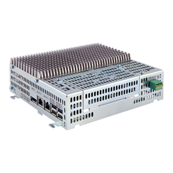
- Page 3 Panel Interface Module PIM 041-W The Panel Interface Module (PIM) is an attachable CPU for SIGMATEK touch panels (TP). This module operates with a high-performance Intel Celeron dual-core processor. The available interfaces are used, among other things, to forward process data. A generous M.2 hard drive serves as the storage medium for the operating system, application and...
-
Page 4: Table Of Contents
PIM 041-W PANEL INTERFACE MODULE Table of Contents 1 Introduction 1.1 Target Group/Purpose of this Operating Manual 1.2 Important Reference Documentation 1.3 Contents of Delivery 2 Basic Safety Guidelines 2.1 Symbols Used 2.2 Disclaimer 2.3 General Safety Guidelines 3 Standards and Guidelines 3.1 Guidelines... - Page 5 PANEL INTERFACE MODULE PIM 041-W 7 Assembly/Installation 7.1 Check Contents of Delivery 7.2 Installation 8 Wiring 8.1 Note 8.2 Grounding 8.3 Shielding 8.4 ESD Protection 8.5 USB Interface 9 Transport/Storage 10 Storage 11 Maintenance 11.1 Service 11.2 Repair 12 Buffer Battery 12.1 Data Retention Battery Change...
-
Page 6: Introduction
1.2 Important Reference Documentation TP XX61 This and additional documents can be downloaded from our website or obtained through support. 1.3 Contents of Delivery 1x PIM 041-W 1x 4-pin Phoenix connector plug 4x M3 TX10 Torx screws Page 4 14.04.2021... -
Page 7: Basic Safety Guidelines
PANEL INTERFACE MODULE PIM 041-W 2 Basic Safety Guidelines 2.1 Symbols Used The following symbols are used in the operator documentation for warning and danger messages, as well as informational notes. DANGER Danger indicates that death or serious injury will occur, if the specified measures are not taken. - Page 8 PIM 041-W PANEL INTERFACE MODULE CAUTION Caution indicates that moderate to slight injury can occur, if the specified measures are not taken. To avoid moderate to slight injuries, observe the all guidelines. Attention indique une situation dangereuse qui, faute de prendre les mesures adéquates, peut entraîner des blessures assez graves ou...
-
Page 9: Disclaimer
Please thoroughly read the corresponding documents and this operating manual before handling a product. SIGMATEK GmbH & Co KG is not liable for damages caused through, non-compliance with these instructions or applicable regulations. -
Page 10: General Safety Guidelines
2006/42/EG guidelines is correct. As long as the machine with which the product should be used does not comply with the guideline, operating this product is prohibited. Operate the unit with devices and accessories approved by SIGMATEK only. Page 8... - Page 11 PANEL INTERFACE MODULE PIM 041-W CAUTION Handle the device with care and do not drop or let fall. Prevent foreign bodies and fluids from entering the device. The device must not be opened, otherwise it could be damaged! Manipulez l’appareil avec précaution et ne le laissez pas tomber.
-
Page 12: Standards And Guidelines
The product was constructed in compliance with the following European Union guidelines and tested for conformity. 3.1.1 EU Conformity Declaration EU Declaration of Conformity The product PIM 041-W conforms to the following European guidelines: 2014/35/EU Low-voltage Guideline 2014/30/EU Electromagnetic Compatibility (EMC Guideline) 2011/65/EU “Restricted use of certain hazardous substances in electrical and electronic equipment”... -
Page 13: Technical Data
4x USB 2.0, Type A 1x DisplayPort V1.2a (max. 1920 x 1200 Pixel at 60 Hz) 2x Ethernet (Gbit) 1x Panel Interface Connector (for connecting a SIGMATEK TP) Internal interfaces USB 3.1 (for touch and front USB, if available on the TP) -
Page 14: Electrical Requirements
PIM 041-W PANEL INTERFACE MODULE 4.2 Electrical Requirements Supply voltage +24 V DC ±20 % (SELV/PELV) UL: Class 2 or LVLC Protection class Current consumption of the typically 600 mA maximum 1100 mA voltage supply (+24 V) (with no external devices... -
Page 15: Environmental Conditions
IP20 protection through housing (not UL-listed) The maximum environmental temperature allowed depends on the TP connected. The ambient temperature cannot exceed any of the permissible values. Applies only if the PIM 041-W is mounted onto the TP. 14.04.2021 Page 13... -
Page 16: Miscellaneous
PIM 041-W PANEL INTERFACE MODULE 4.4 Miscellaneous Article number 01-232-041-W Hardware version Operating system Windows 10 IOT Approvals CAUTION If the modular components (e.g. TP and PIM) are not bolted together,they are NOT ESD-protected and can only be unpacked and handled in an ESD-safe environment by trained personnel. -
Page 17: Interfaces
PIM 041-W 5 Interfaces 5.1 Front Connectors 5.1.1 X1: Supply (4-pin Phoenix RM 3.5) Function +24 V DC +24 V DC 5.1.2 X9: Panel Interface Connector The panel interface connector connects the PIM with the TPs from SIGMATEK. 14.04.2021 Page 15... -
Page 18: Left Side Connectors
PIM 041-W PANEL INTERFACE MODULE 5.2 Left Side Connectors 5.2.1 X2: DisplayPort Output V1.2a Function Lane 0 (p) Lane 0 (n) Lane 1 (p) Lane 1 (n) Lane 2 (p) Lane 2 (n) Lane 3 (p) Lane 3 (n) Config1... -
Page 19: X3, X4: Ethernet 1, 2 10/100/1000 Mbit/S (Rj45)
PANEL INTERFACE MODULE PIM 041-W 5.2.2 X3, X4: Ethernet 1, 2 10/100/1000 Mbit/s (RJ45) Function 5.2.3 X5-X8: USB 2.0 (Type A) Function +5 V, I = 500 mA out,max INFORMATION It should be noted that many of the USB devices on the market do not comply with USB specifications;... -
Page 20: Mechanical Dimensions
PIM 041-W PANEL INTERFACE MODULE 6 Mechanical Dimensions Dimensions 191 x 171.50 x 61 mm (W x H x D) Material housing: sheet steel plate color: blue chromated Weight 1.2 kg Page 18 14.04.2021... -
Page 21: Assembly/Installation
PANEL INTERFACE MODULE PIM 041-W 7 Assembly/Installation 7.1 Check Contents of Delivery Ensure that the contents of the delivery are complete and intact. See chapter 1.3 Contents of Delivery. INFORMATION On receipt and before initial use, check the device for damage. If the device is damaged, contact our customer service and do not install the device in your system. -
Page 22: Wiring
PIM 041-W PANEL INTERFACE MODULE 8 Wiring 8.1 Note DANGER Electric shock With bad cable insulation, there is a danger of electric shock from the device. Use only cable insulation with a temperature resistance greater than 70 °C. Chocs électriques En cas de mauvaise isolation des câbles, l'appareil présente un risque de... -
Page 23: Grounding
PIM 041-W 8.2 Grounding The PIM 041-W is grounded via the TP. The device must be grounded to protective earth (PE) via the blade terminal provided. In addition, ensure that when installing into the control cabinet, a large grounding surface is provided. It is important to establish a low-Ohm connection to ground to ensure error-free function. -
Page 24: Esd Protection
PIM 041-W PANEL INTERFACE MODULE 8.4 ESD Protection CAUTION Typically, USB devices (keyboard, mouse etc.) are equipped with non- shielded cables. These devices are disrupted by ESD and in some instances, no longer function. Généralement, les périphériques USB (clavier, souris etc) ne sont pas équipés de câbles blindés. -
Page 25: Transport/Storage
PANEL INTERFACE MODULE PIM 041-W 9 Transport/Storage INFORMATION This device contains sensitive electronics. During transport and storage, high mechanical stress must therefore be avoided. For storage and transport, the same values for humidity and vibration as for operation must be maintained! Temperature and humidity fluctuations may occur during transport. -
Page 26: Storage
PIM 041-W PANEL INTERFACE MODULE 10 Storage INFORMATION When not in use, store the device according to the storage conditions. See chapter 9 Transport/Storage. During storage, ensure that all protective covers (if available) are placed correctly, so that no contamination, foreign bodies or fluids enter the device. -
Page 27: Maintenance
PANEL INTERFACE MODULE PIM 041-W 11 Maintenance INFORMATION During maintenance as well as servicing, observe the safety instructions from chapter 2 Basic Safety Guidelines. Lors de l'entretien et de la maintenance, respectez les consignes de sécurité du chapitre 2 Basic Safety Guidelines. -
Page 28: Buffer Battery
PIM 041-W PANEL INTERFACE MODULE 12 Buffer Battery A Lithium battery is installed at the manufacturer. The battery has enough capacity to preserve data in the absence of a supply voltage for up to circa 5 years. COMPANY DATA Lithium battery RENATA 3.0 V/235 mAh... -
Page 29: Data Retention Battery Change
PANEL INTERFACE MODULE PIM 041-W 12.1 Data Retention Battery Change The exchangeable buffer battery ensures that the following data is preserved in the absence of a supply voltage: Time BIOS settings If the battery is empty, the following settings are reset or data is deleted:... - Page 30 PIM 041-W PANEL INTERFACE MODULE locking screws. Page 28 14.04.2021...
-
Page 31: Modularity
PANEL INTERFACE MODULE PIM 041-W 13 Modularity INFORMATION The device is not Hot-Plug capable and can be damaged when the supply is not disconnected before inserting or removing the PIM. Always disconnect the supply before inserting or removing. 13.1 Removing the PIM from the Touch Panel CAUTION This product is a sensitive electronic device. -
Page 32: Mounting The Pim Onto The Touch Panel
PIM 041-W PANEL INTERFACE MODULE 5. Slide the PIM in the direction of the upward as shown. 6. Remove the PIM from the TP. 13.2 Mounting the PIM onto the Touch Panel To mount the PIM on a TP, follow the steps below: 1. -
Page 33: Calibrating The Touch Screen
PANEL INTERFACE MODULE PIM 041-W 13.2.1 Calibrating the Touch Screen The touch screen is calibrated at the factory. You should therefore only recalibrate the touch screen when press-point changes are noticed. 14.04.2021 Page 31... -
Page 34: Disposal
PIM 041-W PANEL INTERFACE MODULE 14 Disposal INFORMATION Should you need to dispose of the device, the national electronic scrap regulation must be observed. The device appliance must not be disposed of as household waste. Page 32 14.04.2021... -
Page 35: Accessories
PANEL INTERFACE MODULE PIM 041-W 15 Accessories 15.1 Battery Description Order Number Lithium battery RENATA 01-690-055 with 20 mm strap (one-sided) 14.04.2021 Page 33... - Page 36 PIM 041-W PANEL INTERFACE MODULE Changes Chart Change date Affected Chapter Note page(s) 09.09.2020 Document Restructuring 10 Storage Chapter added 18.02.2021 12 Buffer Battery Data retention added and content restructured 14.04.2021 4.1 Performance Data Hard drive 64-Gbyte Page 34 14.04.2021...
Need help?
Do you have a question about the PIM 041-W and is the answer not in the manual?
Questions and answers