
Related Manuals for SIGMATEK AM 441


Summary of Contents for SIGMATEK AM 441
- Page 1 AM 441 S-DIAS Analog Mixed Module ±10 V Instruction Manual Date of creation: 03.10.2013 Version date: 26.07.2023 Article number: 20-017-441-E...
- Page 2 (print, photocopy, microfilm or in any other process) without the express permission. We reserve the right to make changes in the content without notice. The SIGMATEK GmbH & Co KG is not responsi- ble for technical or printing errors in the handbook and assumes no responsibility for damages that occur through...
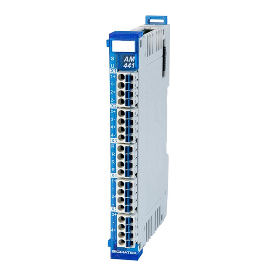
- Page 3 1 reference output The S-DIAS AM 441 analog mixed module has four ±10 V analog outputs with a resolution of 12 bits and four ±10 V analog inputs or 0-100 % po- tentiometer inputs with a 16-bit resolution. For the potentiometer inputs, a 10 V reference is provided which can be loaded with a maximum of 16.7...
-
Page 4: Table Of Contents
AM 441 S-DIAS ANALOG MIXED MODULE ±10 V Contents Introduction ................5 Target Group/Purpose of this Operating Manual ...... 5 Important Reference Documentation ......... 5 Contents of Delivery ..............5 Basic Safety Directives ............6 Symbols Used ................6 Disclaimer ..................8 General Safety Directives ............ - Page 5 S-DIAS ANALOG MIXED MODULE ±10 V AM 441 Mechanical Dimensions ............18 Connector Layout ..............19 Status LEDs ................. 20 Applicable Connectors ............... 20 Label Field ................... 21 Wiring ..................22 Wiring Example ................22 Note ....................23 Connection Variants ..............24 8.3.1...
- Page 6 AM 441 S-DIAS ANALOG MIXED MODULE ±10 V 12 Addressing ................34 Firmware – HW Class Addressing (FW Version V01.00 – 12.1 V01.20) ..................34 Firmware – HW Class Addressing (FW Version ≥ V02.00) ..37 12.2 13 Transport/Storage ..............42 14 Storage ...................42 15 Maintenance ................43...
-
Page 7: Introduction
General knowledge of automation technology is required. Further help and training information, as well as the appropriate accessories can be found on our website www.sigmatek-automation.com. Our support team is happily available to answer your questions. Please see our website for our hotline number and business hours. -
Page 8: Basic Safety Directives
AM 441 S-DIAS ANALOG MIXED MODULE ±10 V Basic Safety Directives Symbols Used The following symbols are used in the operator documentation for warning and danger messages, as well as informational notes: DANGER Danger indicates that death or serious injury will occur, if the speci- fied measures are not taken. - Page 9 S-DIAS ANALOG MIXED MODULE ±10 V AM 441 INFORMATION Information Provides important information on the product, handling or relevant sections of the documentation, which require atten- tion. 26.07.2023 Page 7...
-
Page 10: Disclaimer
It does not guarantee properties under the warranty. Please thoroughly read the corresponding documents and this operat- ing manual before handling a product. SIGMATEK GmbH & Co KG is not liable for damages caused through, non-compliance with these instructions or applicable regulations. -
Page 11: General Safety Directives
S-DIAS ANALOG MIXED MODULE ±10 V AM 441 General Safety Directives The Safety Directives in the other sections of this operating manual must be observed. These instructions are visually emphasized by symbols. INFORMATION According to EU Directives, the operating manual is a component of a product. -
Page 12: Software/Training
AM 441 S-DIAS ANALOG MIXED MODULE ±10 V CAUTION Handle the device with care and do not drop or let fall. Prevent foreign bodies and fluids from entering the device. The device must not be opened! Manipulez l’appareil avec précaution et ne le laissez pas tomber. -
Page 13: Standards And Directives
The product was constructed in compliance with the following European Union directives and tested for conformity. 3.1.1 EU Conformity Declaration EU Declaration of Conformity The product AM 441 conforms to the following European directives: • 2014/35/EU Low-voltage Directive • 2014/30/EU Electromagnetic Compatibility (EMC Directive) •... -
Page 14: Type Plate
AM 441 S-DIAS ANALOG MIXED MODULE ±10 V Type Plate HW: Hardware version SW: Software version Page 12 26.07.2023... -
Page 15: Technical Data
S-DIAS ANALOG MIXED MODULE ±10 V AM 441 Technical Data Analog Inputs Specifications ±10 V or Potentiometer Inputs 0-100 % Number of channels Input type difference input potentiometer input -10 … +10 V Measurement range 0-100 % Measurement value -10,000 ... +10,000 or 0 ... -
Page 16: Reference Output Specifications
AM 441 S-DIAS ANALOG MIXED MODULE ±10 V Reference Output Specifications Number of channels Reference voltage +10 V maximum 10.0 mA (< HW version 3.5) Allowable output current maximum 16.7 mA (≥ HW version 3.5) 2.50 mA (< HW version 3.5) -
Page 17: Electrical Requirements
S-DIAS ANALOG MIXED MODULE ±10 V AM 441 Electrical Requirements Voltage supply from S-DIAS bus +5 V Current consumption on the typically 50 mA maximum 55 mA S-DIAS bus (+5 V supply) Voltage supply from S-DIAS bus +24 V Current consumption on the... - Page 18 AM 441 S-DIAS ANALOG MIXED MODULE ±10 V Page 16 26.07.2023...
-
Page 19: Miscellaneous
S-DIAS ANALOG MIXED MODULE ±10 V AM 441 Miscellaneous Article number 20-017-441 Standard UL 508 (E247993) Approbations UL, cUL, CE Environmental Conditions Storage temperature -20 ... +85 °C Environmental temperature 0 ... +60 °C Humidity 0-95 %, non-condensing Installation altitude above sea... -
Page 20: Mechanical Dimensions
AM 441 S-DIAS ANALOG MIXED MODULE ±10 V Mechanical Dimensions Page 18 26.07.2023... -
Page 21: Connector Layout
S-DIAS ANALOG MIXED MODULE ±10 V AM 441 Connector Layout 26.07.2023 Page 19... -
Page 22: Status Leds
AM 441 S-DIAS ANALOG MIXED MODULE ±10 V Status LEDs Module Status green module active No supply available BLINKING (5 Hz) no communication User yellow can be set from the application (e.g. the module LED can be set to blinking through the... -
Page 23: Label Field
S-DIAS ANALOG MIXED MODULE ±10 V AM 441 Label Field Manufacturer Weidmüller Type MF 10/5 CABUR MC NE WS Weidmüller article number 1854510000 Compatible printer Weidmüller Type Printjet Advanced 230V Weidmüller article number 1324380000 26.07.2023 Page 21... -
Page 24: Wiring
AM 441 S-DIAS ANALOG MIXED MODULE ±10 V Wiring Wiring Example Page 22 26.07.2023... -
Page 25: Note
S-DIAS ANALOG MIXED MODULE ±10 V AM 441 Note To ensure error-free operation, a careful wiring method must be followed: • The 0 V connection of the supply voltage must be connected with the 0 V collection point over the shortest route possible. -
Page 26: Connection Variants
AM 441 S-DIAS ANALOG MIXED MODULE ±10 V Connection Variants 8.3.1 Voltage Measurement of not Potential-free Voltage Sources Connection scheme 1 When using a non potential-free voltage source (voltage source with connection to the ground or GND), the input must be configured as a differential analog input via the soft- ware. -
Page 27: Voltage Measurement Of Potential-Free Voltage Sources
S-DIAS ANALOG MIXED MODULE ±10 V AM 441 8.3.2 Voltage Measurement of Potential-free Voltage Sources Connection scheme 2 When using a potential-free voltage source (voltage source without connection to the earth or GND), the input must either be configured via the software as an "Input with reference to mass"... -
Page 28: Voltage Measurement With A Potentiometer
AM 441 S-DIAS ANALOG MIXED MODULE ±10 V 8.3.3 Voltage Measurement with a Potentiometer Schematic 3 The analog inputs can also be used to connect a potentiometer. The input must be thereby configured via the software as an "input with reference to mass". The analog input x- inter- nal is then connected to AGND. -
Page 29: Connection To Analog Outputs
S-DIAS ANALOG MIXED MODULE ±10 V AM 441 8.3.4 Connection to Analog Outputs Example application: axis control for a DC servo, frequency converter. 26.07.2023 Page 27... -
Page 30: Assembly/Installation
AM 441 S-DIAS ANALOG MIXED MODULE ±10 V Assembly/Installation Check Contents of Delivery Ensure that the contents of the delivery are complete and intact. See chapter Contents of Delivery. INFORMATION On receipt and before initial use, check the device for damage. If the device is damaged, contact our customer service and do not install the device in your system. -
Page 31: Mounting
S-DIAS ANALOG MIXED MODULE ±10 V AM 441 Mounting The S-DIAS modules are designed for installation into the control cabinet. To mount the modules a DIN-rail is required. The DIN rail must establish a conductive connection with the back wall of the control cabinet. The individual S-DIAS modules are mounted on the DIN rail as a block and secured with latches. - Page 32 AM 441 S-DIAS ANALOG MIXED MODULE ±10 V Recommended minimum distances of the S-DIAS modules to the surrounding components or control cabinet wall: a, b, c … distances in mm (inches) Page 30 26.07.2023...
-
Page 33: Expanded Timing Modes (Fw Version ≥ V02.00)
S-DIAS ANALOG MIXED MODULE ±10 V AM 441 10 Expanded Timing Modes (FW version ≥ V02.00) The AM 441can operate the analog inputs in either speed mode (highest possible scan rate) or in time-offset mode (measuring active only once per cycle at a defined time). This can be configured via bit 3 in the Info byte of the configuration data (address 0x0104). - Page 34 AM 441 S-DIAS ANALOG MIXED MODULE ±10 V • Minimum time offset value: Since the firmware must process the incoming cyclic data immediately after the S-DIAS sync, only offset values of 130 µs and higher can be used. • Maximum time offset value: Since cyclic Data for the HW class must be written at the end of an S-DIAS cycle, only offset values up a maximum cycle time below 160 µs can be used.
-
Page 35: Supported Cycle Times
S-DIAS ANALOG MIXED MODULE ±10 V AM 441 11 Supported Cycle Times 11.1 Cycle Times below von 1 ms (in µs) < V3.00 ≥ V3.00 11.2 Cycle Times equal to or higher than 1 ms (in ms) < V3.00 ≥ V3.00 <... -
Page 36: Addressing
AM 441 S-DIAS ANALOG MIXED MODULE ±10 V 12 Addressing 12.1 Firmware – HW Class Addressing (FW Version V01.00 – V01.20) The address allocation defined here applies to the FW versions V01.00, V01.10 and V01.20. for FW version ≥ V02.00, see 12.2. - Page 37 S-DIAS ANALOG MIXED MODULE ±10 V AM 441 cable break detection Bit 0 cable break AI1 Bit 1 cable break AI2 Bit 2 cable break AI3 Bit 3 cable break AI4 Module status 008A Bit 4 reference voltage 0 ... Reference voltage OK 1 ...
- Page 38 AM 441 S-DIAS ANALOG MIXED MODULE ±10 V Configuration of the analog inputs Bit 0 analog input 1 0 … differential analog input 1 ... analog input with reference to mass Bit 1 analog input 2 0 … differential analog input 1 ...
-
Page 39: Firmware - Hw Class Addressing (Fw Version ≥ V02.00)
S-DIAS ANALOG MIXED MODULE ±10 V AM 441 12.2 Firmware – HW Class Addressing (FW Version ≥ V02.00) The address allocation defined here applies to the FW version ≥ V02.00. For older FW versions see 12.1. Address Size Access Type... - Page 40 AM 441 S-DIAS ANALOG MIXED MODULE ±10 V status Bit 0 24 V DC not OK Bit 1 not synchronized Bit 2 FLASH calibration data CRC error Bit 3 FLASH calibration data CRC error Bit 4 invalid calibration data Bit 5...
- Page 41 S-DIAS ANALOG MIXED MODULE ±10 V AM 441 Cable break detection and measurement range testing Bit 0 cable break AI1 (also corresponds to AI1 Overrange when the new features (Bit 2 at address 0x0104) are activated) Bit 1 cable break AI2 (also corresponds to AI2 Overrange when the...
- Page 42 Module version (to distinguish the hardware, only required when time offsets are used to deactivate the deactivate unavailable in and outputs) 0 … AM 221 1 … AM 441 Bit 7 reserved Message Counter (used when bit 2 in the Info-Byte is set to address...
- Page 43 S-DIAS ANALOG MIXED MODULE ±10 V AM 441 Configuration of the analog inputs Bit 0 analog input 1 0 … differential analog input 1 ... analog input with reference to mass Bit 1 analog input 2 0 … differential analog input 1 ...
-
Page 44: Transport/Storage
AM 441 S-DIAS ANALOG MIXED MODULE ±10 V 13 Transport/Storage INFORMATION This device contains sensitive electronics. During transport and stor- age, high mechanical stress must therefore be avoided. For storage and transport, the same values for humidity and vibration as for operation must be maintained! Temperature and humidity fluctuations may occur during transport. -
Page 45: Maintenance
S-DIAS ANALOG MIXED MODULE ±10 V AM 441 15 Maintenance INFORMATION During maintenance as well as servicing, observe the safety instruc- tions from chapter 2 Basic Safety Directives. 15.1 Service This product was constructed for low-maintenance operation. 15.2 Repair INFORMATION In the event of a defect/repair, send the device with a detailed error description to the address listed at the beginning of this document. -
Page 46: Hardware Class Am441
AM 441 S-DIAS ANALOG MIXED MODULE ±10 V 17 Hardware Class AM441 Hardware Class AM441 for the S-DIAS AM441 analog module This hardware class is used to control the AM441 hardware module. The module has 4 analog inputs (+/- 10 V) and 4 analog outputs (+/- 10 V). More information on the hardware can be found in the module documentation. -
Page 47: General
S-DIAS ANALOG MIXED MODULE ±10 V AM 441 17.1 General Class State State This server shows the actual status of the hardware class. Device ID State The device ID of the hardware module is shown in this server. FPGA Version State FPGA version of the module in 16#XY (e.g. -
Page 48: Communication Interfaces
AM 441 S-DIAS ANALOG MIXED MODULE ±10 V AI[1-4] cut off Property In this client, the cutoff frequency for the software low pass filter is set. Value frequency setting options are: 1000 Hz 500 Hz 250 Hz 100 Hz 50 Hz... - Page 49 S-DIAS ANALOG MIXED MODULE ±10 V AM 441 Documentation Changes Change date Affected Chapter Note page(s) 23.10.2013 1.6 Environmental Conditions Vibration resistance added 18.12.2013 Potentiometer inputs added 1.1 Analog Inputs Specifica- Table expanded tions ±10 V or Potentiometer Inputs 0-100 % 1.4 Electrical requirements...
- Page 50 AM 441 S-DIAS ANALOG MIXED MODULE ±10 V 02.10.2015 1.5 Miscellaneous UL, cUL, CE added 18.02.2016 1.4 Electrical requirements Graphic added 09.03.2016 1.1 Analog Inputs Specifica- Input type changed tions ±10 V or Potentiometer Inputs 0-100 % 28.04.2016 5 mounting Graphic distances 17.05.2016...
Need help?
Do you have a question about the AM 441 and is the answer not in the manual?
Questions and answers