
Related Manuals for Stinger HEIGH10 UN1810E-FD5


Summary of Contents for Stinger HEIGH10 UN1810E-FD5
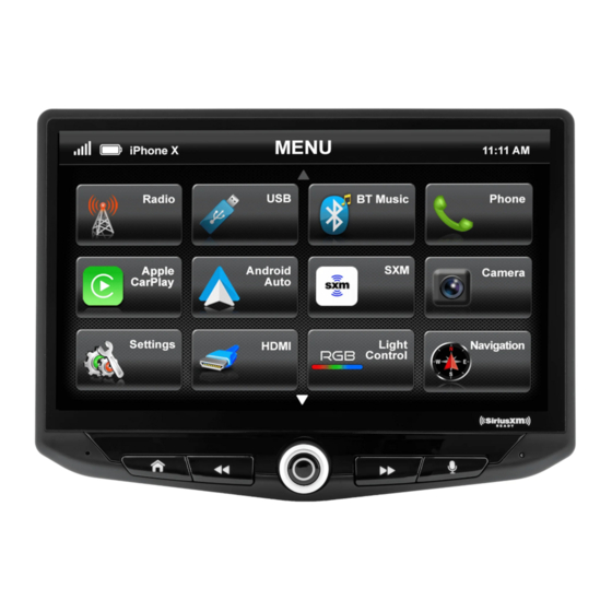
- Page 1 INSTALLATION GUIDE INTEGRATED INFOTAINMENT TOUCH SCREEN SOLUTION FOR FORD TRANSIT CUSTOM 2018 > PART NUMBER: UN1810E-FD5 Copyright © 2023 StingerElectronics-EU.com...
-
Page 2: About This Product
Please note: Compatible for non-amplified basic radio models. CONTENTS • HEIGH10® unit with fitting accessories and wiring • Black double DIN fascia plate (with accessories) • Vehicle retention interface with plug-and-play harness • Vehicle specific antenna adapter (AM/FM/DAB) • Stinger stereo patch lead • Instruction manual www.stingerelectronics-eu.com... - Page 3 FITTING GUIDE STEREO REMOVAL Turn off the ignition and remove the key from the vehicle. Locate the trim panel around the radio on the dashboard. It should be a rectangular panel that surrounds the radio and extends to the vents on either side of the radio. This will need to be removed as a complete unit. Carefully pry off the trim panel using a plastic trim removal tool.
- Page 4 FITTING GUIDE Take the HEIGH10® components and begin to assemble the core components in accordance with the “Installation Manual” that comes with unit. HEIGH10 ASSEMBLY www.stingerelectronics-eu.com...
- Page 5 FITTING GUIDE FASCIA PLATE SET-UP 1. With the HEIGH10® unit configured correctly, attach the fascia brackets to the relevant sides of the radio module using the screws within the kit. Place into the vehicle and roughly test fit with the fascia to measure whether the brackets need moving forwards/backwards.
-
Page 6: Prior To Installation
PRIOR TO INSTALLATION Read the manual prior to installation. Technical knowledge is necessary for installation. The place of installation must be free of moisture and away from heat sources. Please ensure that the correct tools are using during the installation to avoid damage to the vehicle or product. Connects2 can not be held responsible for the installation of this product. - Page 7 INSTALLATION GUIDE See wiring diagram on Pg.4 for more information Before installing the interface, the factory stereo must be removed and disconnected. To do this, please consult the vehicle owner’s manual/handbook or contact a fitting professional. A stereo connection (patch) lead is also required for the installation of this interface (supplied separately). Please ensure that you have the correct lead before proceeding.
-
Page 8: Wiring Diagram
WIRING DIAGRAM Male ISO Connector Vehicle Specific Connector [32 Pin] Connect to aftermarket stereo Connect to corresponding connector from vehicle Flying Wires Purple/White - Reverse Gear Lt. Green - Park Brake Pink - Speed Pulse Main Wiring Loom Connector [14 Pin] Connect to Interface Box Interface Box Stereo Connection (Patch) Lead Connector [12 Pin]... - Page 9 E-Mail: stinger.eu@aampglobal.com Mon - Fri 9am - 5.30pm GMT If you would like to download a digital copy of this manual, or any other product, then please visit the www.Stinger- Electronics-EU.com website. This manual is considered correct at the time of printing but is subject to change. For the latest manuals & updates, refer to our website.
Need help?
Do you have a question about the HEIGH10 UN1810E-FD5 and is the answer not in the manual?
Questions and answers