Table of Contents
Advertisement
Advertisement
Table of Contents

Subscribe to Our Youtube Channel
Related Manuals for Kodak OG-Plus3.24RM


Summary of Contents for Kodak OG-Plus3.24RM
-
Page 2: Table Of Contents
Table Of Contents ABOUT THIS MANUAL ............................1 Purpose ................................1 Scope ................................1 SAFETY INSTRUCTIONS ........................... 1 INTRODUCTION ..............................2 Features ................................2 Basic System Architecture ..........................2 Product Overview ............................. 3 INSTALLATION ..............................4 Unpacking and Inspection ..........................4 Installation ................................ -
Page 3: About This Manual
ABOUT THIS MANUAL Purpose This manual describes the assembly, installation, operation and troubleshooting of this unit. Please read this manual carefully before installations and operations. Keep this manual for future reference. Scope This manual provides safety and installation guidelines as well as information on tools and wiring. SAFETY INSTRUCTIONS WARNING: This chapter contains important safety and operating instructions. -
Page 4: Introduction
INTRODUCTION This is a multi-function inverter/charger, combining functions of inverter, MPPT solar charger and battery charger to offer uninterruptible power support with portable size. Its comprehensive LCD display offers user-configurable and easy-accessible button operation such as battery charging current, AC/solar charger priority, and acceptable input voltage based on different applications. -
Page 5: Product Overview
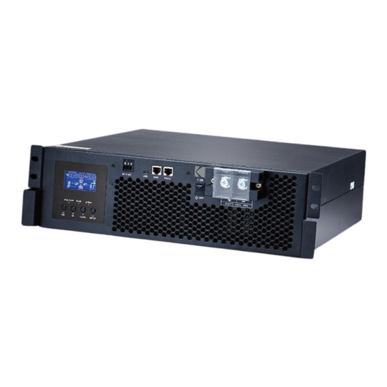
Product Overview Front Back 1. LCD display 2. Status indicator 3. Charging indicator 4. Fault indicator 5. Function buttons 6. Power on/off switch 7. AC input 8. AC output 9. PV input 10. Battery input 11. Parallel communication cable (only for parallel model) 12. -
Page 6: Installation
INSTALLATION Unpacking and Inspection Before installation, please inspect the unit. Be sure that nothing inside the package is damaged. You should have received the following items inside of package: The unit x 1 User manual x 1 Communication cable x 1 ... -
Page 7: Battery Connection
Battery Connection CAUTION: For safety operation and regulation compliance, it’s requested to install a separate DC over-current protector or disconnect device between battery and inverter. It may not be requested to have a disconnect device in some applications, however, it’s still requested to have over-current protection installed. Please refer to typical amperage in below table as required fuse or breaker size. -
Page 8: Ac Input/Output Connection
AC Input/Output Connection CAUTION!! Before connecting to AC input power source, please install a separate AC breaker between inverter and AC input power source. This will ensure the inverter can be securely disconnected during maintenance and fully protected from over current of AC input. The recommended spec of AC breaker is 30A for 3KW and 50A for 5KW. -
Page 9: Pv Connection
4. Make sure the wires are securely connected. CAUTION: Important Be sure to connect AC wires with correct polarity. If L and N wires are connected reversely, it may cause utility short-circuited when these inverters are worked in parallel operation. CAUTION: Appliances such as air conditioner are required at least 2~3 minutes to restart because it’s required to have enough time to balance refrigerant gas inside of circuits. -
Page 10: Communication Connection
Solar Charging Mode INVERTER MODEL OG-Plus 3.24RM OG-Plus 3.48RM OG-Plus 5.48RM Max. PV Array Open Circuit Voltage 145Vdc PV Array MPPT Voltage Range 30~115Vdc 60~115Vdc Please follow below steps to implement PV module connection: 1. Assemble the ring terminal based on the recommended cable and terminal size. -
Page 11: Dry Contact Signal
Dry Contact Signal There is one dry contact (3A/250VAC) available on the rear panel. It could be used to deliver signal to external device when battery voltage reaches warning level. Unit Status Condition Dry contact port: NC & C NO & C Power Off Unit is off and no output is powered. -
Page 12: Operation
OPERATION Power ON/OFF Once the unit has been properly installed and the batteries are connected well, simply press On/Off switch (located on the button of the case) to turn on the unit. Operation and Display Panel The operation and display panel, shown in below chart, is on the front panel of the inverter. It includes three indicators, four function keys and a LCD display, indicating the operating status and input/output power information. -
Page 13: Lcd Display Icons
LCD Display Icons Icon Function description Input Source Information Indicates the AC input. Indicates the PV input Indicate input voltage, input frequency, PV voltage, battery voltage and charger current. Configuration Program and Fault Information Indicates the setting programs. Indicates the warning and fault codes. Warning: flashing with warning code. - Page 14 In battery mode, it will present battery capacity. Load Percentage Battery Voltage LCD Display < 1.717V/cell 1.717V/cell ~ 1.8V/cell Load >50% 1.8 ~ 1.883V/cell > 1.883 V/cell < 1.817V/cell 1.817V/cell ~ 1.9V/cell 50%> Load > 20% 1.9 ~ 1.983V/cell > 1.983 <...
-
Page 15: Lcd Setting
LCD Setting After pressing and holding ENTER button for 3 seconds, the unit will enter setting mode. Press “UP” or “DOWN” button to select setting programs. And then, press “ENTER” button to confirm the selection or ESC button to exit. Setting Programs: Program Description... - Page 16 60A (default) The setting range is from Maximum charging current: 10A to 120A for OG-Plus To configure total charging 3.24RM model and 10A to current for solar and utility 140A for OG-Plus 3.48RM chargers. model. The setting range is (Max. charging current = from 10A to 160A for utility charging current + OG-Plus 5.48RM model.
- Page 17 Restart disable (default) Restart enable Auto restart when overload occurs Restart disable (default) Restart enable Auto restart when over temperature occurs 50Hz (default) 60Hz Output frequency Automatically (default) If selected and utility is available, inverter will work in line mode. Once utility frequency unstable, Operation Logic...
- Page 18 Default setting: 46.0V The setting range is from 44.0V to 57.0V and increment of each click is 1.0V. If “WECO battery” is selected in program 05 Default setting: 10% The parameter will be fixed at 10% SOC of battery. Available options for 24V: Battery fully charged The setting range is from 24.0V to 32.0V and...
- Page 19 SbL: Solar energy for battery Solar energy charge battery first first and disallow the utility UdC: Disallow utility to charge to charge battery. battery SLb: Solar energy for load first Solar energy provides UCb: Allow utility to charge power to the load first and battery also allow the utility to charge battery.
- Page 20 Bypass enable (default) If selected and no matter power ON button is pressed on or not, inverter can work in bypass mode if utility is available. Record enable Record disable (default) Record Fault code 24V default setting: 28.2V Default setting: 56.4V Bulk charging voltage (C.V voltage) If self-defined is selected in program 5, this program can be...
- Page 21 L3 phase: 28 for the inverters connected to L3 phase. Be sure to connect share current cable to units which are on the same phase. Do NOT connect share current cable between units on different phases. 24V default setting: 21.0V 48V default setting: 42.0V Low DC cut-off voltage If self-defined is selected in program 5, this program can be...
- Page 22 60min (default) Setting range is from 5min to 900min. Increment of Battery equalized time each click is 5min. 120min (default) Setting range is from 5min to 900 min. Increment of Battery equalized timeout each click is 5 min. 30days (default) Setting range is from 0 to 90 days.
-
Page 23: Display Setting
For hour setting, the range Time setting – Hour is from 00 to 23. For day setting, the range is Time setting– Day from 00 to 31. month setting, Time setting– Month range is from 01 to 12. For year setting, the range Time setting –... - Page 24 charging current=50A Charging current PV power PV power = 500W Battery voltage=50V, output voltage=230V Battery voltage and output voltage Output frequency=50Hz Output frequency Load percent=70% Load percentage When connected load is lower than 1kVA, load in VA will present xxxVA like below chart. Load in VA When load is larger than 1kVA (≧1KVA), load in VA will present x.xkVA like below chart.
- Page 25 When load is lower than 1kW, load in W will present xxxW like below chart. Load in Watt When load is larger than 1kW (≧1KW), load in W will present x.xkW like below chart. Battery voltage=50V, discharging current=1A Battery voltage/DC discharging current Main CPU version 00014.04 Main CPU version checking Secondary CPU version 00003.03...
-
Page 26: Operating Mode Description
Operating Mode Description Operation mode Description LCD display Charging by utility and PV energy. Charging by utility. Standby mode Note: No output is supplied by the *Standby mode: The inverter unit but it still can charge is not turned on yet but at this batteries. - Page 27 power from the utility. PV energy and utility can charge batteries. Charging by PV Charging by utility No charging No charging and Bypass Fault mode Note: *Fault mode: Errors are Utility can bypass. caused by inside circuit error or external reasons such as No charging over temperature, output short circuited and so on.
-
Page 28: Fault Reference Code
Fault Reference Code Fault Code Fault Event Icon on Fan is locked when inverter is off. Over temperature Battery voltage is too high Battery voltage is too low Output short circuited or over temperature is detected by internal converter components. Output voltage is abnormal. -
Page 29: Warning Indicator
Warning Indicator Warning Warning Event Audible Alarm Icon flashing Code Fan is locked when Beep three times every inverter is on. second Over temperature None Battery is over-charged Beep once every second Low battery Beep once every second Overload Beep once every 0.5 second Output power derating Beep twice every 3 seconds No USB disk is detected. - Page 30 Equalize charging time and timeout In Equalize stage, the controller will supply power to charge battery as much as possible until battery voltage raises to battery equalization voltage. Then, constant-voltage regulation is applied to maintain battery voltage at the battery equalization voltage. The battery will remain in the Equalize stage until setting battery equalized time is arrived.
-
Page 31: Specifications
SPECIFICATIONS Table 1 Line Mode Specifications INVERTER MODEL OG-Plus 3.24RM OG-Plus 3.48RM OG-Plus 5.48RM Input Voltage Waveform Sinusoidal Nominal Input Voltage 230Vac Low Loss Voltage 110Vac± 7V Low Loss Return Voltage 120Vac± 7V High Loss Voltage 280Vac± 7V High Loss Return Voltage 270Vac±... - Page 32 Table 2 Battery Mode Specifications OG-Plus 3.24RM INVERTER MODEL OG-Plus 3.48RM OG-Plus 5.48RM 3KVA/3KW 3KVA/3KW 5KVA/5KW Rated Output Power Pure Sine Wave Output Voltage Waveform 230Vac± 5% Output Voltage Regulation 50Hz or 60Hz Output Frequency Peak Efficiency Overload Protection 5s@≥150% load; 10s@105%~150% load 2* rated power for 5 seconds Surge Capacity Nominal DC Input Voltage...
- Page 33 Table 3 Charge Mode Specifications Utility Charging Mode INVERTER MODEL OG-Plus 3.24RM OG-Plus 3.48RM OG-Plus 5.48RM Charging Current Default: 30A, Default: 30A, max: 60A @ Nominal Input Voltage max: 80A Flooded Bulk 29.2Vdc 58.4Vdc Battery Charging AGM / Gel Voltage 28.2Vdc 56.4Vdc Battery...
- Page 34 Table 4 ECO/Bypass Mode Specifications Bypass Mode INVERTER MODEL OG-Plus 3.24RM OG-Plus 3.48RM OG-Plus 5.48RM Input Voltage Waveform Sinusoidal Low Loss Voltage 176Vac± 7V Low Loss Return Voltage 186Vac± 7V High Loss Voltage 280Vac± 7V High Loss Return Voltage 270Vac± 7V Nominal Input Frequency 50Hz / 60Hz (Auto detection) Low Loss Frequency...
-
Page 35: Trouble Shooting
TROUBLE SHOOTING Problem LCD/LED/Buzzer Explanation / Possible cause What to do Unit shuts down LCD/LEDs and buzzer automatically will be active for 3 The battery voltage is too low 1. Re-charge battery. during startup seconds and then (<1.91V/Cell) 2. Replace battery. process. -
Page 36: Parallel Function
PARALLEL FUNCTION 1. Introduction This inverter can be used in parallel for two applications. 1. Parallel operation in single phase with up to units. The supported maximum output power is 24KW/24KVA for OGPlus3.24/RM OG-Plus 3.48RM model and 40KW/40KVA for OG-Plus 5.48RM model. 2. - Page 37 Step 3: Re-connect 2-pin and 14-pin to original position on parallel board as shown below chart. Step 4: Put parallel cover back to the unit. Now the inverter is providing parallel operation function. 4. Wiring Connection The cable size of each inverter is shown as below: Ring terminal: Recommended battery cable and terminal size for each inverter: Ring Terminal...
- Page 38 Regarding AC input and output, please also follow the same principle. CAUTION!! Please install the breaker at the battery and AC input side. This will ensure the inverter can be securely disconnected during maintenance and fully protected from over current of battery or AC input. The recommended mounted location of the breakers is shown in the figures in 5-1 and 5-2.
- Page 39 4-1. Parallel Operation in Single phase Two inverters in parallel: Power Connection Load Communication Connection Three inverters in parallel: Power Connection Load Communication Connection...
- Page 40 Four inverters in parallel: Power Connection Load Communication Connection Five inverters in parallel: Power Connection Load Communication Connection Six inverters in parallel: Power Connection Load...
- Page 41 Communication Connection Seven inverters in parallel: Power Connection Load Communication Connection ① ② ③ ④ ⑤ ⑥ ⑦ Eight inverters in parallel: Power Connection Load Communication Connection ① ② ③ ④ ⑤ ⑥ ⑦ ⑧...
- Page 42 4-2. Support 3-phase equipment Two inverters in each phase: Power Connection Load Communication Connection Four inverters in one phase and one inverter for the other two phases: Power Connection Load Note: It’s up to customer’s demand to pick 4 inverters on any phase. P1: L1-phase, P2: L2-phase, P3: L3-phase.
- Page 43 Communication Connection Three inverters in one phase, two inverters in second phase and one inverter for the third phase: Power Connection Load Communication Connection Three inverters in one phase and only one inverter for the remaining two phases: Power Connection Load Communication Connection...
- Page 44 Two inverters in two phases and only one inverter for the remaining phase: Power Connection Load Communication Connection Two inverters in one phase and only one inverter for the remaining phases: Power Connection Load Communication Connection...
- Page 45 One inverter in each phase: Power Connection Load Communication Connection WARNING: Do not connect the current sharing cable between the inverters which are in different phases. Otherwise, it may damage the inverters. 5. LCD Setting and Display Setting Program: Program Description Selectable option Single:...
- Page 46 When the units are operated in 3-phase application, please choose “3PX” to define L1 phase: each inverter. It is required to have at least 3 inverters or maximum inverters to support three-phase equipment. It’s required to have at least one inverter in each phase or it’s up to inverters in one phase.
- Page 47 6. Commissioning Parallel in single phase Step 1: Check the following requirements before commissioning: Correct wire connection Ensure all breakers in Line wires of load side are open and each Neutral wires of each unit are connected together. Step 2: Turn on each unit and set “PAL”...
- Page 48 LCD display in L1-phase unit LCD display in L2-phase unit LCD display in L3-phase unit Step 5: If there is no more fault alarm, the system to support 3-phase equipment is completely installed. Step 6: Please switch on all breakers of Line wires in load side. This system will start to provide power to the load.
-
Page 49: Appendix A: Approximate Back-Up Time Table
Appendix A: Approximate Back-up Time Table Model Load (VA) Backup Time @24Vdc 200Ah (min) Backup Time @24Vdc 400Ah (min) 2200 1050 1200 OG-Plus 1500 3.24RM 1800 2100 2400 2700 3000 Model Load (VA) Backup Time @ 48Vdc 200Ah (min) Backup Time @ 48Vdc 400Ah (min) 1226 2576 1000... -
Page 50: Appendix B: Bms Communication Installation
Appendix B: BMS Communication Installation 1. Introduction If connecting to lithium battery, it is recommended to purchase a custom-made RJ45 communication cable. Please check with your dealer or integrator for details. This custom-made RJ45 communication cable delivers information and signal between lithium battery and the inverter. - Page 51 3. Installation and Operation PYLONTECH After configuration, please install LCD panel with inverter and Lithium battery with the following steps. Step 1. Use custom-made RJ45 cable to connect inverter and Lithium battery. Note for parallel system: 1. Only support common battery installation. 2.
- Page 52 WECO Step 1. Use custom-made RJ45 cable to connect inverter and Lithium battery. Note for parallel system: 1. Only support common battery installation. 2. Use custom-made RJ45 cable to connect any inverter (no need to connect to a specific inverter) and Lithium battery.
- Page 53 Note for parallel system: 1. Only support common battery installation. 2. Use custom-made RJ45 cable to connect any inverter (no need to connect to a specific inverter) and Lithium battery. Simply set this inverter battery type to “SOL” in LCD program 5. Others should be “USE”. Step 2.
- Page 54 5. Code Reference Related information code will be displayed on LCD screen. Please check inverter LCD screen for the operation. Code Description Action If battery status is not allowed to charge and discharge after the communication between the inverter and battery is successful, it will show code 60 to stop charging and discharging battery.
-
Page 55: Appendix C: The Wi-Fi Operation Guide In Remote Panel
Appendix C: The Wi-Fi Operation Guide in Remote Panel 1. Introduction Wi-Fi module can enable wireless communication between off-grid inverters and monitoring platform. Users have complete and remote monitoring and controlling experience for inverters when combining Wi-Fi module with WatchPower APP, available for both iOS and Android based device. All data loggers and parameters are saved in iCloud. - Page 56 Then, a “Registration success” window will pop up. Tap “Go now” to continue setting local Wi-Fi network connection. Step 2: Local Wi-Fi Module Configuration Now, you are in “Wi-Fi Config” page. There are detailed setup procedure listed in “How to connect?” section and you may follow it to connect Wi-Fi.
- Page 57 Then, return to WatchPower APP and tap “ ” button when Wi-Fi module is connected successfully. Step 3: Wi-Fi Network settings icon to select your local Wi-Fi router name (to access the internet) and enter password. Step 4: Tap “Confirm” to complete the Wi-Fi configuration between the Wi-Fi module and the Internet. If the connection fails, please repeat Step 2 and 3.
- Page 58 2-3. Login and APP Main Function After finishing the registration and local Wi-Fi configuration, enter registered name and password to login. Note: Tick “Remember Me” for your login convenience afterwards. Overview After login is successfully, you can access “Overview” page to have overview of your monitoring devices, including overall operation situation and Energy information for Current power and Today power as below diagram.
- Page 59 Devices Tap the icon (located on the bottom) to enter Device List page. You can review all devices here by adding or deleting Wi-Fi Module in this page. Add device Delete device icon on the top right corner and enter part number by scanning bar code to add Wi-Fi module. This part number is pasted on the front panel and manually enter it.
- Page 60 2-4. Device List In Device List page, you can pull down to refresh the device information and then tap any device you want to check up for its real-time status and related information as well as to change parameter settings. Please refer to the parameter setting list.
- Page 61 【Battery Mode】 Inverter will power the load from the batter with or without PV charging. Only PV source can charge battery. Device Alarm and Name Modification In this page, tap the icon on the top right corner to enter the device alarm page. Then, you can review alarm history and detailed information.
- Page 62 【Basic Information】 displays basic information of the inverter, including AC voltage, AC frequency, PV input voltage, Battery voltage, Battery capacity, Charging current, Output voltage, Output frequency, Output apparent power, Output active power and Load percent. Please slide up to see more basic information. 【Production Information】displays Model type (Inverter type), Main CPU version and secondary CPU version.
- Page 63 on connected battery type. Back to grid When “SBU” or “SOL” is set as output source priority and battery voltage voltage is lower than this setting voltage, unit will transfer to line mode and the grid will provide power to load. Back to discharge When “SBU”...
- Page 64 Brightness Adjust the lighting brightness Speed Adjust the lighting speed Effects Change the light effects Color selection Adjust color combination to show energy source an battery status Restore to the This function is to restore all settings back to default settings. default...
Need help?
Do you have a question about the OG-Plus3.24RM and is the answer not in the manual?
Questions and answers
Batteries are connected but shows that batteries are not connected (bp) flashes on LCD. What can be the problem?
The Kodak OG-Plus3.24RM may display "bp" on the LCD even when the batteries are connected if communication between the inverter and battery is lost. This can happen if:
1. The battery type is set to “Pylontech Battery,” “WECO Battery,” “Soltaro Battery,” or “BAK Battery.”
2. The communication signal is not detected for 3 minutes after battery connection.
3. The communication is lost after successful connection, causing the buzzer to beep and the inverter to stop charging and discharging after 10 minutes.
This issue may also cause a battery number change or display switching due to communication loss.
This answer is automatically generated