
Related Manuals for Pickering 40-296


Summary of Contents for Pickering 40-296
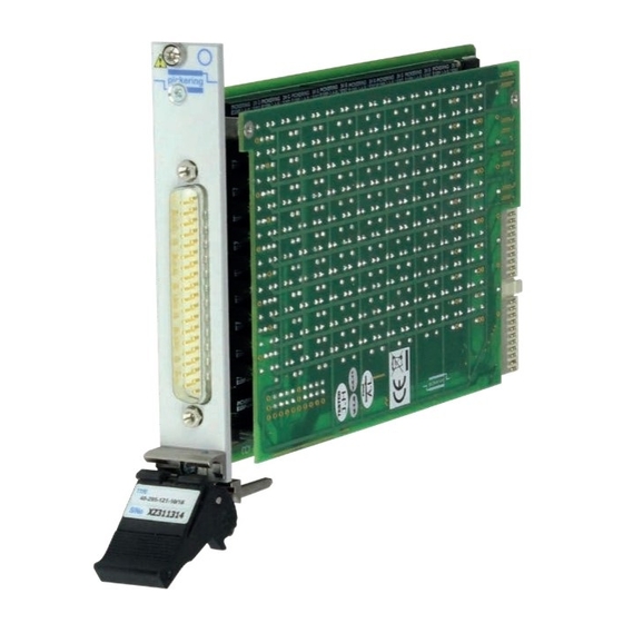
- Page 1 40-296 User Manual PXI Programmable Potentiometer Module pickeringtest.com Issue 6.5 January 2020...
- Page 2 © COPYRIGHT (2020) PICKERING INTERFACES. ALL RIGHTS RESERVED. No part of this publication may be reproduced, transmitted, transcribed, translated or stored in any form, or by any means without the written permission of Pickering Interfaces. Technical details contained within this publication are subject to change without notice.
- Page 3 Pickering Interfaces strives to fulfil all relevant environmental laws and regulations and reduce wastes and releases to the environment. Pickering Interfaces aims to design and operate products in a way that protects the environment and the health and safety of its employees, customers and the public. Pickering Interfaces endeavours to develop and manufacture products that can be produced, distributed, used and recycled, or disposed of, in a safe and environmentally friendly manner.
-
Page 4: Product Safety
If this product is heavy reference should be made to the safety instructions for provisions of lifting and moving. STATIC SENSITIVE To indicate that static sensitive devices are present and handling precautions should be followed. REED RELAY MODULE 40-110/115/120/125 PROGRAMMABLE POTENTIOMETER MODULE 40-296 Page (IV) Page (IV) -
Page 5: Table Of Contents
Pre Operation Checks ............3.1 Hardware Installation ............3.2 Software Installation .............3.2 Testing Operation ..............3.3 Section 4 Programming Guide ..............4.1 Programming Options For Pickering PXI Modules ....4.1 Module Architecture ..............4.2 Programming The Module ............4.2 Section 5 Connector Information ..............5.1 Section 6 Trouble Shooting .................6.1 Section 7 Maintenance Information ............7.1... - Page 6 THIS PAGE INTENTIONALLY BLANK PROGRAMMABLE POTENTIOMETER MODULE 40-296 Page (VI)
-
Page 7: Warnings And Cautions
Not to be used in safety critical circuits, refer to the Pickering Interfaces’ terms & conditions of sale. This module must not be used for the switching of Mains Circuits. For the switching of voltages up to the module’s full specification, Secondary Circuit power supplies and the Device Under Test must... - Page 8 • For suitably equipped products in the event of an emergency press the red “emergency stop” button situated on the front of the unit. PROGRAMMABLE POTENTIOMETER MODULE 40-296 Page (VIII) 2 AMP 1-POLE UHD MATRIX MODULES 40-575 / 576 / 577 / 578 / 579...
-
Page 9: Technical Specification
Resistor 24-Bit 0Ω to 16MΩ 3 or 6 The 40-296 version is wired as a potentiometer with two end connections and a wiper. 8-Bit 0Ω to 255Ω Wiper 5 or 9 The model is available with a variety of channel counts to allow 12-Bit 0Ω... - Page 10 Resistor Chain 4 Resistor Chain 5 Schematic for 5 x 16 bit Resistor Module 40-295-021-5/16 Potentiometer 1 Schematic for 5 x 8 bit Potentiometer Module 40-296-021-5/8 High Density Resistor Module (40-295-121/40-296-121) Programmable Resistor Soft Front Panel Low Density Resistor Module (40-295-021/40-296-021) pickeringtest.com...
- Page 11 Module weight: 200g (40-295-021-3/24) performance and excellent contact resistance stability. 240g (40-295-021-10/8) 340g (40-295-121-10/16) All reed relays are manufactured by our sister company Pickering Electronics: pickeringrelay.com 3D models for all versions in a variety of popular file formats are available on request.
- Page 12 40-296-121-4/16 Product Customization 1 x 24 Bit Pot (0Ω to 16MΩ Wiper) 40-296-021-1/24 Pickering PXI modules are designed and manufactured on our own 3x 24 Bit Pot (0Ω to 16MΩ Wiper) 40-296-121-3/24 flexible manufacturing lines, giving complete product control and enabling simple customization to meet very specific requirements.
- Page 13 We provide a full range of supporting cable and connector solutions for all our switching products—20 connector families with 1200+ products. We offer everything from simple mating connectors to complex cables assemblies and terminal blocks. All assemblies are manufactured by Pickering and are guaranteed to mechanically and electrically mate to our modules. Connectors & Backshells...
- Page 14 Programmable Resistor – 40-295/296 Programming Pickering provide kernel, IVI and VISA (NI & Keysight) drivers which are compatible with all Microsoft supported versions of Windows and popular older versions. For a list of all supporting operating systems, please see: pickeringtest.com/os The VISA driver is also compatible with Real-Time Operating Systems such as LabVIEW RT.
-
Page 15: Functional Description
A functional block diagram is provided in Figure 2.1. Figures 2.2 and 2.3 provide examples of potentiometer chain schematic diagrams for the 40-296-121-9/8 version of the card. The Programmable Potentiometer Card is powered by +5V inputs via the PXI connector, J1. The interface to the user test equipment is via the front panel mounted 37-pin D-type connector, J2. - Page 16 109-1-A 109-1-A 109-1-A 109-1-A 109-1-A 109-1-A 109-1-A 109-1-A RS80 RS79 RS78 RS77 RS76 RS75 RS74 RS73 RS90 CH5_Wiper CH5 Terminal A LK10 LINK_3 Figure 2.2 - Programmable Potentiometer Module 40-296-121-9/8: Motherboard Example Schematic Diagram PROGRAMMABLE POTENTIOMETER MODULE 40-296 Page 2.2...
- Page 17 LINK_3 109-1-A 109-1-A 109-1-A 109-1-A 109-1-A 109-1-A 109-1-A 109-1-A RS64 RS63 RS62 RS61 RS60 RS59 RS658 RS57 RS88 CH9_Wiper CH9 Terminal A LINK_3 Figure 2.3 - Programmable Potentiometer Module 40-296-121-9/8: Daughterboard Example Schematic Diagram PROGRAMMABLE POTENTIOMETER MODULE 40-296 Page 2.3...
- Page 18 SECTION 2 - TECHNICAL DESCRIPTION pickering THIS PAGE INTENTIONALLY BLANK PROGRAMMABLE POTENTIOMETER MODULE 40-296 Page 2.4...
-
Page 19: Installation
Modular products require installation in a suitable PXI/LXI chassis. The module is designed for indoor use only. PREOPERATION CHECKS (UNPACKING) 1. Check the module for transport damage and report any damage immediately to Pickering Interfaces. Do not attempt to install the product if any damage is evident. -
Page 20: Hardware Installation
For a system comprising more than one chassis, turn ON the last chassis in the system followed by the penultimate, etc, and finally turn ON the external controller or chassis containing the system controller. 9. For Pickering Interfaces modular LXI installation there is no requirement to use any particular power up sequence. -
Page 21: Testing Operation
Figure 3.2 - General Soft Front Panel Icon A selector panel will appear, listing all installed Pickering PCI, PXI or LXI switch cards and resistor cards. Click on the card you wish to control, and a graphical control panel is presented allowing operation of the card. - Page 22 SECTION 3 - INSTALLATION pickering THIS PAGE INTENTIONALLY BLANK PROGRAMMABLE POTENTIOMETER MODULE 40-296 Page 3.4...
-
Page 23: Programming Guide
SECTION 4 - PROGRAMMING GUIDE PROGRAMMING OPTIONS FOR PICKERING INTERFACES PXI MODULES For information on the installation and use of drivers and the programming of Pickering’s products in various software environments, please refer to the Software User Manual. This is available as a download from: https://www.pickeringtest.com/support/software-drivers-and-downloads... -
Page 24: Module Architecture
MODULE ARCHITECTURE The 8-bit version of the 40-296 Potentiometer Module is available with 5 or 9 separate channels which can be programmed with values between 0Ω and 255Ω. 12-bit, 16-bit and 24-bit versions are also available which have fewer channels and a greater resistance range - see the Specifications section for details. - Page 25 SECTION 4 - PROGRAMMING GUIDE pickering Here are examples of using the drivers with the 8-bit versions of the 40-296. Other versions operate in the same way but have a different number of bits in their sub-units. Using PILPXI To operate a relay the user could use the simple OpBit command or the WriteSub commands OpBit DWORD sub_unit = 1;...
- Page 26 ViUInt32 data[1]; data[0] = 0x3F03; // Operates bits 1, 2, 9, 10, 11, 12, 13 and 14 pipx40_setChannelPattern( vi, sub_unit, data); data[0] = 0; // Releases all bits of channel pipx40_setChannelPattern( vi, sub_unit, data); PROGRAMMABLE POTENTIOMETER MODULE 40-296 Page 4.4...
- Page 27 SECTION 4 - PROGRAMMING GUIDE pickering Table 4.1 - 40-296 - 8-Bit Versions - Sub-Unit, Resistor & Relay Cross Reference Sub- Channel/ Resistor Relay Sub- Channel/ Resistor Relay Sub- Channel/ Resistor Relay Unit Resistor Value Unit Resistor Value Unit Resistor...
- Page 28 SECTION 4 - PROGRAMMING GUIDE pickering Table 4.2 - 40-296 - 12-Bit Versions - Sub-Unit, Resistor & Relay Cross Reference Sub- Channel/ Resistor Relay Sub- Channel/ Resistor Relay Sub- Channel/ Resistor Relay Unit Resistor Value Unit Resistor Value Unit Resistor...
- Page 29 SECTION 4 - PROGRAMMING GUIDE pickering Table 4.3 - 40-296 - 16-Bit Versions - Sub-Unit, Resistor & Relay Cross Reference Sub- Channel/ Resistor Relay Sub- Channel/ Resistor Relay Sub- Channel/ Resistor Relay Unit Resistor Value Unit Resistor Value Unit Resistor...
- Page 30 SECTION 4 - PROGRAMMING GUIDE pickering Table 4.4 - 40-296 - 24-Bit Versions - Sub-Unit, Resistor & Relay Cross Reference Sub- Channel/ Resistor Relay Sub- Channel/ Resistor Relay Sub- Channel/ Resistor Relay Unit Resistor Value Unit Resistor Value Unit Resistor...
-
Page 31: Connector Information
Figure 5.1 - Potentiometer Module Pinout: Figure 5.2 - Potentiometer Module Pinout: 40-296-021-1/24 40-296-121-3/24 1 Channel, 24-Bit 3 Channels, 24-Bit (37-pin Male D-Type Connector (37-pin Male D-Type Connector Viewed From Front of Module) Viewed From Front of Module) PROGRAMMABLE POTENTIOMETER MODULE 40-296 Page 5.1... - Page 32 40-296-021-2/12 40-296-121-4/12 & 40-296-021-2/16 & 40-296-121-4/16 2 Channels, 12 & 16-Bit 4 Channels, 12 & 16-Bit (37-pin Male D-Type Connector (37-pin Male D-Type Connector Viewed From Front of Module) Viewed From Front of Module) PROGRAMMABLE POTENTIOMETER MODULE 40-296 Page 5.2...
- Page 33 Figure 5.5 - Potentiometer Module Pinout: Figure 5.6 - Potentiometer Module Pinout: 40-296-021-5/8 40-296-121-9/8 5 Channels, 8-Bit 9 Channels, 8-Bit (37-pin Male D-Type Connector (37-pin Male D-Type Connector Viewed From Front of Module) Viewed From Front of Module) PROGRAMMABLE POTENTIOMETER MODULE 40-296 Page 5.3...
- Page 34 SECTION 5 - CONNECTOR INFORMATION pickering THIS PAGE INTENTIONALLY BLANK PROGRAMMABLE POTENTIOMETER MODULE 40-296 Page 5.4...
-
Page 35: Trouble Shooting
PCI configuration, highlighting any potential configuration problems. Specific details of all installed Pickering switch cards are included. All the installed Pickering switch cards should be listed in the “Pilpxi information” section - if one or more cards is missing it may be possible to determine the reason by referring to the PCI configuration dump contained in the report, but interpretation of this information is far from straightforward, and the best course is to contact Pickering support: support@pickeringtest.com, if possible... - Page 36 SECTION 6 - TROUBLE SHOOTING pickering THIS PAGE INTENTIONALLY BLANK PROGRAMMABLE POTENTIOMETER MODULE 40-296 Page 6.2...
-
Page 37: Maintenance Information
For PXI modules which are supported in one of Pickering Interfaces’ Modular LXI Chassis (such as the 60-102B and 60-103B) no module software update is required. If the module was introduced after the LXI chassis was manufactured the module may not be recognized, in this case the chassis firmware may need upgrading. - Page 38 SECTION 7 - MAINTENANCE INFORMATION pickering Table 7.1 - 40-296 - 8-Bit Versions - Relay Look-Up Table (relays highlighted in blue are on the motherboard, relays highlighted in yellow are on the daughterboard) Resis- Resis- Resis- Resis- Chan. Relay Chan.
- Page 39 SECTION 7 - MAINTENANCE INFORMATION pickering Table 7.2 - 40-296 - 12-Bit Versions - Relay Look-Up Table (relays highlighted in blue are on the motherboard, relays highlighted in yellow are on the daughterboard) Resis- Resis- Resis- Resis- Chan. Relay Chan.
- Page 40 SECTION 7 - MAINTENANCE INFORMATION pickering Table 7.3 - 40-296 - 16-Bit Versions - Relay Look-Up Table (relays highlighted in blue are on the motherboard, relays highlighted in yellow are on the daughterboard) Resis- Resis- Resis- Resis- Chan. Relay Chan.
- Page 41 SECTION 7 - MAINTENANCE INFORMATION pickering Table 7.4 - 40-296 - 24-Bit Versions - Relay Look-Up Table (relays highlighted in blue are on the motherboard, relays highlighted in yellow are on the daughterboard) Resis- Resis- Resis- Resis- Chan. Relay Chan.
- Page 42 RL57 RL68 RL67 RL66 RL65 RL72 RL71 RL70 RL69 RL76 RL75 RL74 RL73 RL80 RL79 RL78 RL77 Figure 7.1 - 40-296 Motherboard Component Layout RL10 RL11 RL12 RL13 RL14 RL15 RL16 RL17 RL18 RL19 RL20 RL21 RL22 RL23 RL24 RL25...
-
Page 43: Calibration
The 40-296 should be tested with a 6.5 digit DMM or better. The user must use a 4 terminal resistance measurement to avoid the introduction of errors due to leads. - Page 44 To aid users to establish test limits the following generic tables should be used for the standard modules. The tables can be copied to record the results for each channel. Similar principles can be applied to custom modules, if guidance is needed please consult your Pickering Interfaces representative.
- Page 45 SECTION 7 - MAINTENANCE INFORMATION pickering Table 7.6 - Calibration Test Results For 40-296 (8-Bit Versions) Serial Number: Channel Number: Date of Test: Operator’s Name: Test Equipment Used: Result Resistance Nominal Measured Maximum Minimum (delete as Setting Value Value Value...
- Page 46 SECTION 7 - MAINTENANCE INFORMATION pickering Table 7.7 - Calibration Test Results For 40-296 (12-Bit Versions) Serial Number: Channel Number: Date of Test: Operator’s Name: Test Equipment Used: Result Resistance Nominal Measured Maximum Minimum (delete as Setting Value Value Value...
- Page 47 SECTION 7 - MAINTENANCE INFORMATION pickering Table 7.8 - Calibration Test Results For 40-296 (16-Bit Versions) Serial Number: Channel Number: Date of Test: Operator’s Name: Test Equipment Used: Result Resistance Nominal Measured Maximum Minimum (delete as Setting Value Value Value...
- Page 48 SECTION 7 - MAINTENANCE INFORMATION pickering Table 7.9 - Calibration Test Results For 40-296 (24-Bit Versions) Serial Number: Channel Number: Date of Test: Operator’s Name: Test Equipment Used: Result Resistance Nominal Measured Maximum Minimum (delete as Setting Value Value Value...
Need help?
Do you have a question about the 40-296 and is the answer not in the manual?
Questions and answers