
Related Manuals for Pickering 40-220A


Summary of Contents for Pickering 40-220A
- Page 1 40-220A/225A User Manual PXI Digital I/O Breadboard & Prototyping Module pickeringtest.com Issue 4.1 January 2020...
- Page 2 © COPYRIGHT (2020) PICKERING INTERFACES. ALL RIGHTS RESERVED. No part of this publication may be reproduced, transmitted, transcribed, translated or stored in any form, or by any means without the written permission of Pickering Interfaces. Technical details contained within this publication are subject to change without notice.
- Page 3 Pickering Interfaces strives to fulfil all relevant environmental laws and regulations and reduce wastes and releases to the environment. Pickering Interfaces aims to design and operate products in a way that protects the environment and the health and safety of its employees, customers and the public. Pickering Interfaces endeavours to develop and manufacture products that can be produced, distributed, used and recycled, or disposed of, in a safe and environmentally friendly manner.
-
Page 4: Product Safety
If this product is heavy reference should be made to the safety instructions for provisions of lifting and moving. STATIC SENSITIVE To indicate that static sensitive devices are present and handling precautions should be followed. REED RELAY MODULE 40-110/115/120/125 PXI BREADBOARD & PROTOTYPING MODULE 40-220A/225A Page (IV) Page (IV) -
Page 5: Table Of Contents
Pre Operation Checks ............3.1 Hardware Installation ............3.2 Software Installation .............3.2 Testing Operation ..............3.3 Section 4 Programming Options For Pickering PXI Modules ....4.1 Digital Input-Output Sub Units ..........4.2 Using the Direct I/O Driver or VISA Driver ......4.5 Section 5 Connector Information ..............5.1 Section 6 Trouble Shooting .................6.1... - Page 6 THIS PAGE INTENTIONALLY BLANK PXI BREADBOARD & PROTOTYPING MODULE 40-220A/225A Page (VI)
-
Page 7: Warnings And Cautions
Not to be used in safety critical circuits, refer to the Pickering Interfaces’ terms & conditions of sale. This module must not be used for the switching of Mains Circuits. For the switching of voltages up to the module’s full specification, Secondary Circuit power supplies and the Device Under Test must... - Page 8 • For suitably equipped products in the event of an emergency press the red “emergency stop” button situated on the front of the unit. PXI BREADBOARD & PROTOTYPING MODULE 40-220A/225A Page (VIII) 2 AMP 1-POLE UHD MATRIX MODULES 40-575 / 576 / 577 / 578 / 579...
-
Page 9: Technical Specification
• Programmable Attenuators • Filters • Special Circuits to Drive External Relays Digital I/O Capability of the • Mounting Special Relay Types 40-220A Breadboard Module • Dummy Multiplexer Channels for Calibration Purposes pickeringtest.com PXI BREADBOARD & PROTOTYPING MODULE 40-220A/225A Page 1.1... - Page 10 Up to 90% non-condensing 40-225A PXI Prototype Module Altitude: 5000m The 40-255A is a “stripped down“ version of the 40-220A - a very Storage and Transport Conditions basic, low cost, prototype module. It has no PXI interface, but has Storage Temperature: -20°C to +75°C...
- Page 11 40-225A-811 40-225A-812 Product Customization Pickering PXI modules are designed and manufactured on our own flexible manufacturing lines, giving complete product control and enabling simple customization to meet very specific requirements. All customized products are given a unique part number, fully documented and may be ordered at any time in the future.
- Page 12 We provide a full range of supporting cable and connector solutions for all our switching products—20 connector families with 1200+ products. We offer everything from simple mating connectors to complex cables assemblies and terminal blocks. All assemblies are manufactured by Pickering and are guaranteed to mechanically and electrically mate to our modules. Connectors & Backshells...
- Page 13 Breadboard/Prototype Module – 40-220A/225A Programming Pickering provide kernel, IVI and VISA (NI & Keysight) drivers which are compatible with all Microsoft supported versions of Windows and popular older versions. For a list of all supporting operating systems, please see: pickeringtest.com/os The VISA driver is also compatible with Real-Time Operating Systems such as LabVIEW RT.
- Page 14 SECTION 1 - TECHNICAL SPECIFICATION pickering THIS PAGE INTENTIONALLY BLANK PXI BREADBOARD & PROTOTYPING MODULE 40-220A/225A Page 1.6...
-
Page 15: Technical Description
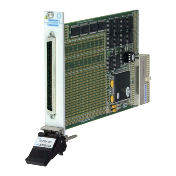
CPCI Ejector Handle • Front Panel mounted with connector type specified by part number • Four 32 bit TTL I/O Drivers (40-220A only) • Four 32 bit Open Collector I/O Drivers (40-220A only) • Breadboard area • Compact PCI backplane connector •... -
Page 16: Functional Description
FUNCTIONAL DESCRIPTION A functional block diagram for the 40-220A Breadboard Module is provided in Figure 2.3. The Module accepts +12V, -12V, +5V, +3.3V supplies from the PXI backplane via Compact PCI connector J1, these power rails are protected by fuses. The interface to the user test equipment is via the front panel mounted connector J2, the type of connector fitted to the module is determined by the part number suffix. -
Page 17: Guidance On Using The Module
Figure 2.4 - Breadboard/Prototyping Module Component Layout Note: The uncommitted power rail wiring points are fully isolated from the module power supplies. To ground reference the uncommitted supplies to the module supplies add a wire link. PXI BREADBOARD & PROTOTYPING MODULE 40-220A/225A Page 2.3... - Page 18 SECTION 2 - TECHNICAL DESCRIPTION pickering 100.00mm 13.83mm 90.12mm 57.73mm 3.76mm 4.00mm Figure 2.5 - Breadboard/Prototyping Module - Dimensions Including Location of Holes For Mounting a Daughterboard PXI BREADBOARD & PROTOTYPING MODULE 40-220A/225A Page 2.4...
- Page 19 SECTION 2 - TECHNICAL DESCRIPTION pickering 92.66mm 90.12mm 54.56mm 72.34mm 74.88mm 92.66mm Figure 2.6 - Breadboard/Prototyping Module - Dimensions of Wiring Points PXI BREADBOARD & PROTOTYPING MODULE 40-220A/225A Page 2.5...
- Page 20 SECTION 2 - TECHNICAL DESCRIPTION pickering THIS PAGE INTENTIONALLY BLANK PXI BREADBOARD & PROTOTYPING MODULE 40-220A/225A Page 2.6...
-
Page 21: Installation
Modular products require installation in a suitable PXI/LXI chassis. The module is designed for indoor use only. PREOPERATION CHECKS (UNPACKING) 1. Check the module for transport damage and report any damage immediately to Pickering Interfaces. Do not attempt to install the product if any damage is evident. -
Page 22: Hardware Installation
For a system comprising more than one chassis, turn ON the last chassis in the system followed by the penultimate, etc, and finally turn ON the external controller or chassis containing the system controller. 9. For Pickering Interfaces modular LXI installation there is no requirement to use any particular power up sequence. -
Page 23: Testing Operation
Figure 3.2 - General Soft Front Panel Icon A selector panel will appear, listing all installed Pickering PCI, PXI or LXI switch cards and resistor cards. Click on the card you wish to control, and a graphical control panel is presented allowing operation of the card. - Page 24 SECTION 3 - INSTALLATION pickering THIS PAGE INTENTIONALLY BLANK PXI BREADBOARD & PROTOTYPING MODULE 40-220A/225A Page 3.4...
-
Page 25: Programming Options For Pickering Pxi Modules
SECTION 4 - PROGRAMMING GUIDE PROGRAMMING OPTIONS FOR PICKERING INTERFACES PXI MODULES For information on the installation and use of drivers and the programming of Pickering’s products in various software environments, please refer to the Software User Manual. This is available as a download from: https://www.pickeringtest.com/support/software-drivers-and-downloads... -
Page 26: Digital Input-Output Sub Units
32 Channels at once using WriteSub or setChannelPattern as a DWORD where Channel 1 is LSB and Channel 32 is MSB. Note: The functions above shown in bold are the commonly used functions. PXI BREADBOARD & PROTOTYPING MODULE 40-220A/225A Page 4.2... - Page 27 SECTION 4 - PROGRAMMING GUIDE pickering Table 4.1 - 40-220A Input Sub-Unit TTL Input Sub-Unit Channel Note: All inputs are fitted with a 10kΩ pull-up resistor to +5V. PXI BREADBOARD & PROTOTYPING MODULE 40-220A/225A Page 4.3...
- Page 28 SECTION 4 - PROGRAMMING GUIDE pickering Table 4.2 - 40-220A Output Sub-Unit TTL Output Open Collector Transistor Sub-Unit Channel Note: The cathode of each open collector output flyback diode is connected to the Vcom wiring point. Apply the relavent power rail to the Vcom wiring point to implement the flyback diode feature.
-
Page 29: Using The Direct I/O Driver Or Visa Driver
Once the drivers are installed the manual “Sys40Prg.pdf” and driver help files which fully describes these functions can be found in the Pickering folder(s) or the Pickering entries on your Start Menu. The card must be opened before use and closed after using the following function calls: Direct I/O Driver - Open with PIL_OpenCards or PIL_OpenSpecifiedCard and close with PIL_CloseCards or PIL_CloseSpecifiedCards respectively. - Page 30 SECTION 4 - PROGRAMMING GUIDE pickering THIS PAGE INTENTIONALLY BLANK PXI BREADBOARD & PROTOTYPING MODULE 40-220A/225A Page 4.6...
- Page 31 " " PIN 95 TO HOLE 95 PIN 96 TO HOLE 96 OUTPUT INPUT CONNECTION CONNECTION Figure 5.1 - Pin Outs: Breadboard Module 40-220A-00X & Prototyping Module 40-225A-10X (96-pin micro-D male connector) PXI BREADBOARD & PROTOTYPING MODULE 40-220A/225A Page 5.1...
- Page 32 SECTION 5 - CONNECTOR INFORMATION pickering Figure 5.2 - User Pin Outs: Breadboard Modules 40-220A-001/002 & Prototyping Modules 40-225A-101/102 (96-pin micro-D male connector viewed from front of module) PXI BREADBOARD & PROTOTYPING MODULE 40-220A/225A Page 5.2...
- Page 33 SECTION 5 - CONNECTOR INFORMATION pickering Figure 5.3 - User Pin Outs: Breadboard Modules 40-220A-201/202 & Prototyping Modules 40-225A-201/202 (37-pin D-type male connector viewed from front of module, connector is panel mounted solder-bucket type) PXI BREADBOARD & PROTOTYPING MODULE 40-220A/225A...
- Page 34 SECTION 5 - CONNECTOR INFORMATION pickering Figure 5.4 - User Pin Outs: Breadboard Modules 40-220A-301/302 & Prototyping Modules 40-225A-301/302 (25-pin D-type male connector viewed from front of module, connector is panel mounted solder-bucket type) PXI BREADBOARD & PROTOTYPING MODULE 40-220A/225A...
- Page 35 SECTION 5 - CONNECTOR INFORMATION pickering Figure 5.5 - User Pin Outs: Breadboard Modules 40-220A-401/402 & Prototyping Modules 40-225A-401/402 (78-pin D-type male connector viewed from front of module, connector is panel mounted solder-bucket type) PXI BREADBOARD & PROTOTYPING MODULE 40-220A/225A...
- Page 36 SECTION 5 - CONNECTOR INFORMATION pickering Figure 5.6 - User Pin Outs: Breadboard Modules 40-220A-501/502 & Prototyping Modules 40-225A-501/502 (50-pin D-type male connector viewed from front of module, connector is panel mounted solder-bucket type) PXI BREADBOARD & PROTOTYPING MODULE 40-220A/225A...
- Page 37 SECTION 5 - CONNECTOR INFORMATION pickering Figure 5.7 - User Pin Outs: Breadboard Modules 40-220A-601/602 & Prototyping Modules 40-225A-601/602 (15-pin D-type male connector viewed from front of module, connector is panel mounted solder-bucket type) PXI BREADBOARD & PROTOTYPING MODULE 40-220A/225A...
- Page 38 SECTION 5 - CONNECTOR INFORMATION pickering Figure 5.8 - User Pin Outs: Breadboard Modules 40-220A-701/702 & Prototyping Modules 40-225A-701/702 (9-pin D-type male connector viewed from front of module, connector is panel mounted solder-bucket type) PXI BREADBOARD & PROTOTYPING MODULE 40-220A/225A...
- Page 39 SECTION 5 - CONNECTOR INFORMATION pickering Figure 5.9 - User Pin Outs: Breadboard Modules 40-220A-801/802 & Prototyping Modules 40-225A-801/802 (20-pin GMCT male connector viewed from front of module, connector is panel mounted solder-bucket type) PXI BREADBOARD & PROTOTYPING MODULE 40-220A/225A...
- Page 40 SECTION 5 - CONNECTOR INFORMATION pickering Figure 5.10 - User Pin Outs: Breadboard Modules 40-220A-811/812 & Prototyping Modules 40-225A-811/812 (2x20-pin GMCT male connectors viewed from front of module, connectors are panel mounted solder-bucket type) PXI BREADBOARD & PROTOTYPING MODULE 40-220A/225A...
-
Page 41: Trouble Shooting
PCI configuration, highlighting any potential configuration problems. Specific details of all installed Pickering switch cards are included. All the installed Pickering switch cards should be listed in the “Pilpxi information” section - if one or more cards is missing it may be possible to determine the reason by referring to the PCI configuration dump contained in the report, but interpretation of this information is far from straightforward, and the best course is to contact Pickering support: support@pickeringtest.com, if possible... - Page 42 SECTION 6 - TROUBLE SHOOTING pickering THIS PAGE INTENTIONALLY BLANK PXI BREADBOARD & PROTOTYPING MODULE 40-220A/225A Page 6.2...
-
Page 43: Maintenance Information
PCB layout diagrams to identify the position of faulty relays. If the module fails it is recommended that it is returned to Pickering Interfaces to repair. While Pickering Interfaces will do its its best to preserve the user circuits installed on the module we cannot guarantee to repair the modules without impacting the user parts, and we reserve the right to replace the module with a new one which does not contain the user circuits in the event that a fault is impossible to diagnose or uneconomic to repair. - Page 44 SECTION 7 - MAINTENANCE INFORMATION pickering THIS PAGE INTENTIONALLY BLANK PXI BREADBOARD & PROTOTYPING MODULE 40-220A/225A Page 7.2...
Need help?
Do you have a question about the 40-220A and is the answer not in the manual?
Questions and answers