
Subscribe to Our Youtube Channel
Related Manuals for Pickering 40-265


Summary of Contents for Pickering 40-265
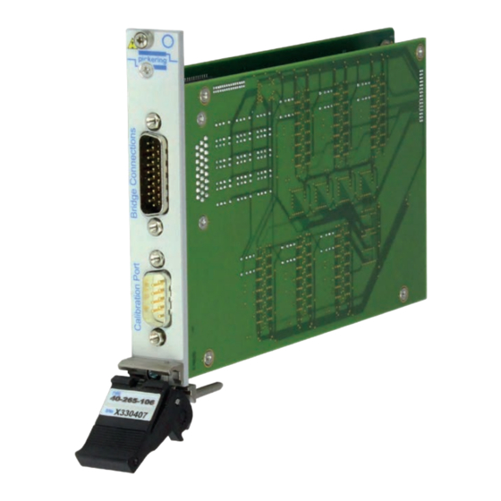
- Page 1 40-265 User Manual PXI Strain Gauge Simulator Module pickeringtest.com Issue 7.3 March 2021...
- Page 2 © COPYRIGHT (2021) PICKERING INTERFACES. ALL RIGHTS RESERVED. No part of this publication may be reproduced, transmitted, transcribed, translated or stored in any form, or by any means without the written permission of Pickering Interfaces. Technical details contained within this publication are subject to change without notice.
- Page 3 Pickering Interfaces strives to fulfil all relevant environmental laws and regulations and reduce wastes and releases to the environment. Pickering Interfaces aims to design and operate products in a way that protects the environment and the health and safety of its employees, customers and the public. Pickering Interfaces endeavours to develop and manufacture products that can be produced, distributed, used and recycled, or disposed of, in a safe and environmentally friendly manner.
-
Page 4: Product Safety
If this product is heavy reference should be made to the safety instructions for provisions of lifting and moving. STATIC SENSITIVE To indicate that static sensitive devices are present and handling precautions should be followed. REED RELAY MODULE 40-110/115/120/125 STRAIN GAUGE SIMULATOR MODULE 40-265 Page (IV) Page (IV) -
Page 5: Table Of Contents
Pre Operation Checks ............3.1 Hardware Installation ............3.2 Software Installation .............3.2 Testing Operation ..............3.3 Section 4 Programming Guide ..............4.1 Programming Options For Pickering PXI Modules ....4.1 Module Architecture ..............4.2 Programming The Module ............4.2 Using The Soft Front Panel ..........4.7 Section 5 Connector Information ..............5.1 Section 6 Troubleshooting ................6.1... - Page 6 THIS PAGE INTENTIONALLY BLANK STRAIN GAUGE SIMULATOR MODULE 40-265 Page (VI)
-
Page 7: Warnings And Cautions
Not to be used in safety critical circuits, refer to the Pickering Interfaces’ terms & conditions of sale. This module must not be used for the switching of Mains Circuits. For the switching of voltages up to the module’s full specification, Secondary Circuit power supplies and the Device Under Test must... - Page 8 • For suitably equipped products in the event of an emergency press the red “emergency stop” button situated on the front of the unit. STRAIN GAUGE SIMULATOR MODULE 40-265 Page (VIII) 2 AMP 1-POLE UHD MATRIX MODULES 40-575 / 576 / 577 / 578 / 579...
-
Page 9: Technical Specification
Supported by PXI or LXI Chassis y 3 Year Warranty The 40-265 is ideal for testing strain gauge meters in a wide variety of industrial control systems. It provides 6, 4 or 2 channels of low cost simulation with excellent performance and is a simple way of replacing in-house developed sensors. - Page 10 † Internal ±5 V DC source can be used. Excitation port is EN55011:2009+A1:2010. disconnected when card power is off. ‡ Bridge Output disconnected when card power is off. The 40-265 uses innovative techniques which are the subject of protected Pickering intellectual property rights. Calibration Port Function: Allows connection to any of the strain gauge bridges.
- Page 11 SECTION 1 - TECHNICAL SPECIFICATION pickering Ordering Information Strain Gauge Simulator, 40-265 Product Order Codes Mating Connectors & Cabling 6 Channel Strain Gauge Simulator: For connection accessories for the 40-265 please refer 350 Ω 40-265-016 to the 90-009D 26-pin D-Type and 90-003D 9-pin D-Type 1 kΩ...
- Page 12 We provide a full range of supporting cable and connector solutions for all our switching products—20 connector families with 1200+ products. We offer everything from simple mating connectors to complex cables assemblies and terminal blocks. All assemblies are manufactured by Pickering and are guaranteed to mechanically and electrically mate to our modules. Connectors & Backshells...
- Page 13 Strain Gauge Simulator, 40-265 Programming Pickering provide kernel, IVI and VISA (NI & Keysight) drivers which are compatible with all Microsoft supported versions of Windows and popular older versions. For a list of all supporting operating systems, please see: pickeringtest.com/os The VISA driver is also compatible with Real-Time Operating Systems such as LabVIEW RT.
- Page 14 SECTION 1 - TECHNICAL SPECIFICATION pickering THIS PAGE INTENTIONALLY BLANK STRAIN GAUGE SIMULATOR MODULE 40-265 Page 1.6...
-
Page 15: Technical Description
FROM OTHER STRAIN GAUGE CHANNELS CH1 Excite1 PROGRAMMABLE RESISTOR CH1 Excite2 Calibration Internal Excitation Source CH1 Out1 Calibration Port Connector CH1 Out2 Figure 2.1 - Strain Gauge Simulator Module 40-265: Functional Block Diagram STRAIN GAUGE SIMULATOR MODULE 40-265 Page 2.1... -
Page 16: Guidance On Using The Module
GUIDANCE ON USING THE MODULE The 40-265-01x strain gauge simulator consists of 6, 4 or 2 bridge networks with a resistance of 350Ω in each arm. One arm is a precise but adjustable resistor, the value of which can be varied ±2% of 350Ω with a resolution of 2mΩ. - Page 17 The 40-265 calibration data includes the resistance value at which the bridge is balanced. This will not be precisely 350Ω in the case of 40-265-01x, it could for example be 350.05Ω. If the variable resistor is set to 350.05Ω in this example the bridge is simulating a balanced condition.
- Page 18 The calibration port is designed so that it can be daisy chained with other resistor modules (for example multiple modules of 40-265). A cable assembly can be purchased as an accessory for this purpose or the user can make their own as shown in Figure 2.3.
-
Page 19: Installation
Modular products require installation in a suitable PXI/LXI chassis. The module is designed for indoor use only. PREOPERATION CHECKS (UNPACKING) 1. Check the module for transport damage and report any damage immediately to Pickering Interfaces. Do not attempt to install the product if any damage is evident. -
Page 20: Hardware Installation
For a system comprising more than one chassis, turn ON the last chassis in the system followed by the penultimate, etc, and finally turn ON the external controller or chassis containing the system controller. 9. For Pickering Interfaces modular LXI installation there is no requirement to use any particular power up sequence. -
Page 21: Testing Operation
Figure 3.2 - General Soft Front Panel Icon A selector panel will appear, listing all installed Pickering PCI, PXI or LXI switch cards and resistor cards. Click on the card you wish to control, and a graphical control panel is presented allowing operation of the card. - Page 22 SECTION 3 - INSTALLATION pickering THIS PAGE INTENTIONALLY BLANK STRAIN GAUGE SIMULATOR MODULE 40-265 Page 3.4...
-
Page 23: Programming Guide
SECTION 4 - PROGRAMMING GUIDE PROGRAMMING OPTIONS FOR PICKERING INTERFACES PXI MODULES For information on the installation and use of drivers and the programming of Pickering’s products in various software environments, please refer to the Software User Manual. This is available as a download from: https://www.pickeringtest.com/support/software-drivers-and-downloads... -
Page 24: Module Architecture
SECTION 4 - PROGRAMMING GUIDE pickering MODULE ARCHITECTURE The 40-265 comprises 6, 4 or 2 programmable resistance sub-units, 6, 4 or 2 sub-units to control the bridge connections and a calibration multiplexer sub-unit. Sub-Unit Size 6-Channel Versions 4-Channel Versions 2-Channel Versions... - Page 25 PIPLX_ResGetResistance() LabVIEW The 40-265 does not have the means to set short or open circuit. The card is calibrated in the factory and part of this calibration establishes the resistance required to balance the bridge. This value is stored in the internal memory of the card and may be obtained using the resistor info function:...
- Page 26 NumValues = 1; //read 1 value ViAReal64 Data, Resistance; //get balance value pipx40_readCalibrationFP(session, subUnit, pipx40_CAL_STORE_USER, offset, NumValues, Data); //set resistance = balance value pipx40_resSetResistance(session, subUnit, pipx40_RES_MODE_SET, Data); //check actual resistance set pipx40_resGetResistance(session, subUnit, &Resistance); LabVIEW STRAIN GAUGE SIMULATOR MODULE 40-265 Page 4.4...
- Page 27 For example to energise the bridge switch pair: pipx40_setChannelState (session, sub-unit, ch=4, action=TRUE); LabVIEW To set a sub-unit to external excitation, output enable and bridge switches closed: DWORD data[1]; data[0] = 0x0e; pipx40_setChannelPattern (session, sub-unit, data); LabVIEW STRAIN GAUGE SIMULATOR MODULE 40-265 Page 4.5...
- Page 28 PORT V,Ω+ Source+ PROGRAMMABLE CH1 Excite1 RESISTOR EXCITATION PORT CH1 Excite2 INTERNAL EXCITATION SOURCE CH1 Out1 BRIDGE OUTPUT CH1 Out2 Figure 4.2 - Strain Gauge Simulator Channel Showing Connection of the Calibration Port STRAIN GAUGE SIMULATOR MODULE 40-265 Page 4.6...
-
Page 29: Using The Soft Front Panel
SECTION 4 - PROGRAMMING GUIDE pickering USING THE SOFT FRONT PANEL STRAIN GAUGE SIMULATOR MODULE 40-265 Page 4.7... - Page 30 SECTION 4 - PROGRAMMING GUIDE pickering THIS PAGE INTENTIONALLY BLANK STRAIN GAUGE SIMULATOR MODULE 40-265 Page 4.8...
-
Page 31: Connector Information
SECTION 5 - CONNECTOR INFORMATION pickering SECTION 5 - CONNECTOR INFORMATION Figure 5.1 - Strain Gauge Simulator Module 40-265: Connector Positions STRAIN GAUGE SIMULATOR MODULE 40-265 Page 5.1... - Page 32 CH2 Out.1 CH3 Excite.2 CH1 Excite.2 CH2 Excite.2 CH3 Excite.1 CH1 Excite.1 CH2 Excite.1 Figure 5.3 - “Bridge Connections” Connector Pinouts For 4-Channel Versions (26-pin male high density D-type viewed from front of module) STRAIN GAUGE SIMULATOR MODULE 40-265 Page 5.2...
- Page 33 V,Ω+, Source+ I+, Sense+ I+, Sense+ V,Ω-, Source- V,Ω-, Source- I-, Sense- I-, Sense- FP_GND Figure 5.5 - “Calibration Port” Connector Pinouts For All Versions (9-pin male D-type viewed from front of module) STRAIN GAUGE SIMULATOR MODULE 40-265 Page 5.3...
- Page 34 SECTION 5 - CONNECTOR INFORMATION pickering THIS PAGE INTENTIONALLY BLANK STRAIN GAUGE SIMULATOR MODULE 40-265 Page 5.4...
-
Page 35: Troubleshooting
PCI configuration, highlighting any potential configuration problems. Specific details of all installed Pickering switch cards are included. All the installed Pickering switch cards should be listed in the “Pilpxi information” section - if one or more cards is missing it may be possible to determine the reason by referring to the PCI configuration dump contained in the report, but interpretation of this information is far from straightforward, and the best course is to contact Pickering support: support@pickeringtest.com, if possible... - Page 36 SECTION 6 - TROUBLE SHOOTING pickering THIS PAGE INTENTIONALLY BLANK STRAIN GAUGE SIMULATOR MODULE 40-265 Page 6.2...
-
Page 37: Maintenance Information
For PXI modules which are supported in one of Pickering Interfaces’ Modular LXI Chassis (such as the 60-102B and 60-103B) no module software update is required. If the module was introduced after the LXI chassis was manufactured the module may not be recognized, in this case the chassis firmware may need upgrading. -
Page 38: Verification & Calibration
Example: Agilent 34410A or 34411A • A cable assembly to connect the DMM to the 40-265. This can be constructed by the user or the user can purchase a ready made cable from Pickering Interfaces suitable for connecting to the Bridge Connections port. - Page 39 Figure 7.2 - 40-265 Soft Front Panel - Used For Verification Procedure Calibration/Adjustment Procedure In normal use the 40-265 does not require regular adjustment however in the unlikely event the module may be returned to the Pickering for re-calibration and rewriting the internal calibration values. Adjustment requires a high performance DMM and an automated program taking measurements from the calibration port in order to maintain its accuracy.
-
Page 40: Verification Test Results
SECTION 7 - MAINTENANCE INFORMATION pickering VERIFICATION TEST RESULTS Table 7.1 - Calibration Test Results For 40-265-01x Serial Number: Channel Number: Date of Test: Operator’s Name: Test Equipment Used: % Balance Measured Result (delete Point Min. mV Nominal mV Max. mV... - Page 41 SECTION 7 - MAINTENANCE INFORMATION pickering Table 7.2 - Calibration Test Results For 40-265-10x, 40-265-20x, 40-265-30x & 40-265-40x Serial Number: Channel Number: Date of Test: Operator’s Name: Test Equipment Used: % Balance Measured Result (delete Point Min. mV Nominal mV Max.
- Page 42 SECTION 7 - MAINTENANCE INFORMATION pickering Table 7.3 - Calibration Test Results For 40-265-006 (This version has now been superseded by the 40-265-016) Serial Number: Channel Number: Date of Test: Operator’s Name: Test Equipment Used: % Balance Measured Result (delete Point Min.
Need help?
Do you have a question about the 40-265 and is the answer not in the manual?
Questions and answers