
Related Manuals for Pickering 40-290-021


Summary of Contents for Pickering 40-290-021
- Page 1 sales@artisantg.com artisantg.com (217) 352-9330 | Visit our website - Click HERE...
- Page 2 40-290/291 User Manual PXI Programmable Resistor Module pickeringtest.com Issue 9.3 March 2021...
- Page 3 © COPYRIGHT (2021) PICKERING INTERFACES. ALL RIGHTS RESERVED. No part of this publication may be reproduced, transmitted, transcribed, translated or stored in any form, or by any means without the written permission of Pickering Interfaces. Technical details contained within this publication are subject to change without notice.
- Page 4 Pickering Interfaces strives to fulfil all relevant environmental laws and regulations and reduce wastes and releases to the environment. Pickering Interfaces aims to design and operate products in a way that protects the environment and the health and safety of its employees, customers and the public. Pickering Interfaces endeavours to develop and manufacture products that can be produced, distributed, used and recycled, or disposed of, in a safe and environmentally friendly manner.
-
Page 5: Product Safety
PRODUCT SAFETY SAFETY SYMBOLS The following safety symbols may be used on the product and throughout the product documentation. MEANING / DESCRIPTION SYMBOL PROTECTIVE EARTH (GROUND) To identify any terminal which is intended for connection to an external conductor for protection against electric shock in case of a fault, or the terminal of a protective earth (ground) electrode. -
Page 6: Table Of Contents
Hardware Installation ............3.2 Software Installation .............3.2 Testing Operation ..............3.3 Section 4 Programming Guide ..............4.1 Programming Options For Pickering PXI Modules ....4.1 Module Architecture 40-290-021 .........4.2 Module Architecture 40-290-121 .........4.3 Module Architecture 40-291-021 .........4.4 Module Architecture 40-291-121 .........4.5 Programming The Module ............4.6 Section 5 Connector Information ..............5.1... - Page 7 THIS PAGE INTENTIONALLY BLANK PROGRAMMABLE RESISTOR MODULES 40-290/291 Page (VI)
-
Page 8: Warnings And Cautions
Not to be used in safety critical circuits, refer to the Pickering Interfaces’ terms & conditions of sale. This module must not be used for the switching of Mains Circuits. For the switching of voltages up to the module’s full specification, Secondary Circuit power supplies and the Device Under Test must... - Page 9 CAUTION - PRODUCT DOCUMENTATION SYMBOL Suitably qualified & trained users should ensure that the accompanying documentation is fully read and understood before attempting to install or operate the product. SAFETY INSTRUCTIONS SAFETY INSTRUCTIONS All cleaning and servicing requires the equipment to be isolated and disconnected from the power source and user I/O signals (refer to the Maintenance Section).
- Page 10 Programmable From 0 Ω to 32767.5 Ω in 0.5 Ω Steps y Built-In Non-Volatile Parametric Memory For Calibration Data y Option To Include 16 SPDT Reed Relays y Uses High Reliability Pickering Reed Relays For Maximum Performance y Over 1000 Value Changes Per Second y Special Versions Built To Order y VISA, IVI &...
-
Page 11: Technical Specification
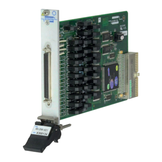
SECTION 1 - TECHNICAL SPECIFICATION pickering Specifications Programmable Resistor, 40-290/291 Mechanical Characteristics Relay Type Single slot 3U PXI (CompactPCI card). The 40-290 & 40-291 are fitted with ruthenium sputtered 3D models for all versions in a variety of popular file reed relays offering very long life with good low level formats are available on request. - Page 12 Other Resistor Modules Dual 16-Bit Resistor Module 40-290-021 Pickering Interfaces manufacture a range of variable resistor modules in the PXI format. If you have a (resistor value is 0 Ω to 32,767.5 Ω excluding residual requirement for a variable resistor module please contact...
- Page 13 We provide a full range of supporting cable and connector solutions for all our switching products—20 connector families with 1200+ products. We offer everything from simple mating connectors to complex cables assemblies and terminal blocks. All assemblies are manufactured by Pickering and are guaranteed to mechanically and electrically mate to our modules. Connectors & Backshells...
- Page 14 Supporting Products & Software Programmable Resistor, 40-290/291 Programming Pickering provide kernel, IVI and VISA (NI & Keysight) drivers which are compatible with all Microsoft supported versions of Windows and popular older versions. For a list of all supporting operating systems, please see: pickeringtest.com/os The VISA driver is also compatible with Real-Time Operating Systems such as LabVIEW RT.
- Page 15 SECTION 1 - TECHNICAL SPECIFICATION pickering THIS PAGE INTENTIONALLY BLANK PROGRAMMABLE RESISTOR MODULES 40-290/291 Page 1.6...
-
Page 16: Technical Description
SECTION 2 - TECHNICAL DESCRIPTION pickering SECTION 2 - TECHNICAL DESCRIPTION FUNCTIONAL DESCRIPTION A functional block diagram is provided in Figure 2.1. The Module is powered by a +5V input via Compact PCI connector J1. The interface to the user test equipment is via the front panel mounted 68-pin micro-D connector, J2. - Page 17 SECTION 2 - TECHNICAL DESCRIPTION pickering 96-PIN MICRO-D CONNECTOR RL37 TO RL48 RELAY CONTACTS RELAY COILS RELAY DRIVERS U13 AND COMPACT PCI CONNECTOR CONTROL LOGIC RL17 TO RL32, RL35 AND RL36 U3, U4, U5, U6 RELAY CONTACTS RELAY COILS TERMINATING...
- Page 18 These cards support non-volatile storage of a 16-bit calibration value associated with every individual resistor in each resistor-chain. The Pickering software drivers provide functions allowing the storage and retrieval of these values, but their interpretation is left entirely to the user’s program.
- Page 19 SECTION 2 - TECHNICAL DESCRIPTION pickering RESISTOR CHAIN 1 RESISTOR CHAIN 2 RESISTOR CHAIN 3 RESISTOR CHAIN 4 RLS1 RLS9 RLS17 RLS25 128R 128R RLS2 RLS10 RLS18 RLS26 256R 256R RLS3 RLS11 RLS19 RLS27 512R 512R RLS4 RLS12 RLS20 RLS28...
-
Page 20: Installation
Modular products require installation in a suitable PXI/LXI chassis. The module is designed for indoor use only. PREOPERATION CHECKS (UNPACKING) 1. Check the module for transport damage and report any damage immediately to Pickering Interfaces. Do not attempt to install the product if any damage is evident. -
Page 21: Hardware Installation
For a system comprising more than one chassis, turn ON the last chassis in the system followed by the penultimate, etc, and finally turn ON the external controller or chassis containing the system controller. 9. For Pickering Interfaces modular LXI installation there is no requirement to use any particular power up sequence. -
Page 22: Testing Operation
Figure 3.2 - General Soft Front Panel Icon A selector panel will appear, listing all installed Pickering PCI, PXI or LXI switch cards and resistor cards. Click on the card you wish to control, and a graphical control panel is presented allowing operation of the card. - Page 23 SECTION 3 - INSTALLATION pickering THIS PAGE INTENTIONALLY BLANK PROGRAMMABLE RESISTOR MODULES 40-290/291 Page 3.4...
-
Page 24: Programming Guide
SECTION 4 - PROGRAMMING GUIDE PROGRAMMING OPTIONS FOR PICKERING INTERFACES PXI MODULES For information on the installation and use of drivers and the programming of Pickering’s products in various software environments, please refer to the Software User Manual. This is available as a download from: https://www.pickeringtest.com/support/software-drivers-and-downloads... -
Page 25: Module Architecture 40-290-021
MODULE ARCHITECTURE 40-290-021 The 40-290-021 Module utilises 32 SPST relays. In the default state, all relay signal paths are open circuit and all resistors are linked in the chains. Energising a particular relay creates a signal path between the C and A terminals of the relay and short circuits the corresponding resistor. -
Page 26: Module Architecture 40-290-121
SECTION 4 - PROGRAMMING GUIDE pickering MODULE ARCHITECTURE 40-290-121 The 40-290-121 Module utilises 32 SPST relays, and 16 SPDT changeover relays. In the default state all signal paths are open circuit for the SPST relays with all resistors linked in the chains, and between the C and B terminals for the changeover relays. -
Page 27: Module Architecture 40-291-021
SECTION 4 - PROGRAMMING GUIDE pickering MODULE ARCHITECTURE 40-291-021 The 40-291-021 Module utilises 32 SPST relays. In the default state, all relay signal paths are open circuit and all resistors are linked in the chains. Energising a particular relay creates a signal path between the C and A terminals of the relay and short circuits the corresponding resistor. -
Page 28: Module Architecture 40-291-121
SECTION 4 - PROGRAMMING GUIDE pickering MODULE ARCHITECTURE 40-291-121 The 40-291-121 Module utilises 32 SPST relays, and 16 changeover relays. In the default state all signal paths are open circuit for the SPST relays with all resistors linked in the chains, and between the C and B terminals for the changeover relays. -
Page 29: Programming The Module
SECTION 4 - PROGRAMMING GUIDE pickering PROGRAMMING THE MODULE Here are examples of using the drivers with the 40-290-021 (32 x SPST) module. For further information please refer to the help information supplied with the software. Using PILPXI To operate a relay the user could use the simple OpBit command or the WriteSub commands OpBit DWORD sub_unit = 1;... - Page 30 (40-290-021/121) R2. OUT R2. OUT R2. OUT R2. OUT SPDT Uncommitted Relays Pins 2-25 and 36-59 (40-290-121 only) 40-290-121 40-290-021 Figure 5.1 - Pinouts: 40-290-021/121 (68-pin female micro-D connector viewed from front of module) PROGRAMMABLE RESISTOR MODULES 40-290/291 Page 5.1...
- Page 31 SECTION 5 - CONNECTOR INFORMATION pickering R1. IN R1. IN R1. OUT R1. OUT R1. IN R1. OUT R1. IN R1. OUT R2. IN R2. OUT R2. IN R2. OUT R2. IN R2. OUT R2. IN R2. OUT SPST R3. IN R3.
-
Page 32: Trouble Shooting
PCI configuration, highlighting any potential configuration problems. Specific details of all installed Pickering switch cards are included. All the installed Pickering switch cards should be listed in the “Pilpxi information” section - if one or more cards is missing it may be possible to determine the reason by referring to the PCI configuration dump contained in the report, but interpretation of this information is far from straightforward, and the best course is to contact Pickering support: support@pickeringtest.com, if possible... - Page 33 SECTION 6 - TROUBLE SHOOTING pickering THIS PAGE INTENTIONALLY BLANK PROGRAMMABLE RESISTOR MODULES 40-290/291 Page 6.2...
-
Page 34: Maintenance Information
For PXI modules which are supported in one of Pickering Interfaces’ Modular LXI Chassis (such as the 60-102B and 60-103B) no module software update is required. If the module was introduced after the LXI chassis was manufactured the module may not be recognized, in this case the chassis firmware may need upgrading. -
Page 35: Calibration
SECTION 7 - MAINTENANCE INFORMATION pickering CALIBRATION The 40-290 and 40-291 have no user adjustable components. In most applications regular calibration is not required; however for applications where a routine calibration is required for a system we suggest the following functional test for the module. - Page 36 To aid users to establish test limits the following generic tables should be used for the standard modules. The tables can be copied to record the results for each channel. Similar principles can be applied to custom modules, if guidance is needed please consult your Pickering Interfaces representative.
- Page 37 SECTION 7 - MAINTENANCE INFORMATION pickering Table 7.2 - Calibration Test Results For 40-290 (Dual 16-Bit) Serial Number: Channel Number: Date of Test: Operator’s Name: Test Equipment Used: Result Resistance Nominal Measured Maximum Minimum (delete as Setting Value Value Value...
- Page 38 SECTION 7 - MAINTENANCE INFORMATION pickering Table 7.3 - Calibration Test Results For 40-291 (Quad 8-Bit) Serial Number: Channel Number: Date of Test: Operator’s Name: Test Equipment Used: Result Resistance Nominal Measured Maximum Minimum (delete as Setting Value Value Value...
- Page 39 PCB. The tables can be used in the fault finding process and should be used in conjunction with the corresponding PCB layout diagrams to identify the position of faulty relays. TABLE 7.4 - Dual 16-Bit Programmable Resistor Module 40-290-021: Relay Numbering Programmable Resistor Module (40-290-021)
- Page 40 SECTION 7 - MAINTENANCE INFORMATION pickering TABLE 7.5 - Dual 16-Bit Programmable Resistor Module 40-290-121: Relay Numbering Programmable Resistor Module (40-290-121) Uncommitted Relay Relay Chain Chain Relays Bit 1 Bit 1 RL17 RL33 Bit 2 Bit 2 RL18 RL34 Bit 3...
- Page 41 SECTION 7 - MAINTENANCE INFORMATION pickering TABLE 7.6 - Quad 8-Bit Programmable Resistor Module 40-291-021: Relay Numbering Programmable Resistor Module (40-291-021) Relay Relay Chain Chain Bit 1 Bit 1 RL17 Bit 2 Bit 2 RL18 Bit 3 Bit 3 RL19...
- Page 42 SECTION 7 - MAINTENANCE INFORMATION pickering TABLE 7.7 - Quad 8-Bit Programmable Resistor Module 40-291-121: Relay Numbering Programmable Resistor Module (40-291-121) Uncommitted Relay Relay Chain Chain Relays Bit 1 Bit 1 RL17 RL33 Bit 2 Bit 2 RL18 RL34 Bit 3...
- Page 43 SECTION 7 - MAINTENANCE INFORMATION pickering Figure 7.6 - Programmable Resistor Module 40-290-121 PROGRAMMABLE RESISTOR MODULES 40-290/291 Page 7.10...
Need help?
Do you have a question about the 40-290-021 and is the answer not in the manual?
Questions and answers