
Related Manuals for Pickering 40-727


Summary of Contents for Pickering 40-727
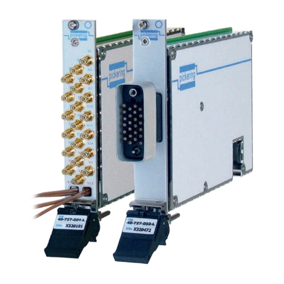
- Page 1 40-727/728/729 User Manual PXI Expandable RF Matrix Module pickeringtest.com Issue 3.5 September 2021...
- Page 2 Pickering Interfaces. Technical details contained within this publication are subject to change without notice. ISO 9001 Reg No. FM38792 EXPANDABLE RF MATRIX MODULE 40-727 / 728 / 729 REED RELAY MODULE 40-110/115/120/125 Page (II) Page (II)
- Page 3 Pickering Interfaces strives to fulfil all relevant environmental laws and regulations and reduce wastes and releases to the environment. Pickering Interfaces aims to design and operate products in a way that protects the environment and the health and safety of its employees, customers and the public. Pickering Interfaces endeavours to develop and manufacture products that can be produced, distributed, used and recycled, or disposed of, in a safe and environmentally friendly manner.
-
Page 4: Product Safety
If this product is heavy reference should be made to the safety instructions for provisions of lifting and moving. STATIC SENSITIVE To indicate that static sensitive devices are present and handling precautions should be followed. REED RELAY MODULE 40-110/115/120/125 EXPANDABLE RF MATRIX MODULE 40-727 / 728 / 729 Page (IV) Page (IV) -
Page 5: Table Of Contents
Connector Information ..............5.1 Section 6 Trouble Shooting .................6.1 Section 7 Maintenance Information ............7.1 Switching System Test Tools ..........7.1 Relay Lookup Tables .............7.1 Appendix A Custom Version - 40-727-901-L ..........A.1 EXPANDABLE RF MATRIX MODULE 40-727 / 728 / 729 Page (V) - Page 6 THIS PAGE INTENTIONALLY BLANK EXPANDABLE RF MATRIX MODULE 40-727 / 728 / 729 Page (VI)
-
Page 7: Warnings And Cautions
Unused slots in the host chassis are populated with blanking plates to prevent access to user I/O signals that may be present. Blanking panels are available to order from Pickering in a variety of slot widths. If the product is not used in this manner for example by using an extender card then additional care must be taken to avoid contact with exposed signals. - Page 8 THIS PAGE INTENTIONALLY BLANK EXPANDABLE RF MATRIX MODULE 40-727 / 728 / 729 Page (VIII)
-
Page 9: Technical Specification
For more information go to: pickeringtest.com/ebirst minimum loss of bandwidth. LOOP-THRU SWITCHES ISOLATION SWITCHES ISOLATION SWITCHES ISOLATION SWITCHES 40-729 8x4 Matrix With 40-729 8x4 Matrix Without Loop-Thru Optional Loop-Thru LOOP-THRU pickeringtest.com EXPANDABLE RF MATRIX MODULE 40-727 / 728 / 729 Page 1.1... - Page 10 SWITCHES 40-728 16x2 Matrix With Optional Loop-Thru LOOP-THRU ISOLATION SWITCHES 40-727 16x4 Matrix Without Loop-Thru LOOP-THRU SWITCHES ISOLATION SWITCHES ISOLATION SWITCHES 40-727 16x4 Matrix With Optional Loop-Thru LOOP-THRU pickeringtest.com EXPANDABLE RF MATRIX MODULE 40-727 / 728 / 729 Page 1.2...
- Page 11 Y Isolation interconnect each 16x4 Switches X Isolation Matrix module) Switches Input Isolation Switches Y Connections 3 off 40-727-001-L 16x4 RF Matrix Modules Interconnected as a 48x4 Matrix pickeringtest.com EXPANDABLE RF MATRIX MODULE 40-727 / 728 / 729 Page 1.3...
- Page 12 VSWR plots which also include the performance of a typical signal path between X4 and Y2. For more information on how performance is distributed throughout the matrix, please refer to the user manual. 40-727 50 Ω Insertion Loss For X to Y Signal Paths 40-727 50 Ω Insertion Loss For Y Loop-Thru Paths 40-727 50 Ω...
- Page 13 Specifications Expandable RF Matrix, 40-727/728/729 40-727 75 Ω Insertion Loss For X to Y Signal Paths 40-727 75 Ω Insertion Loss For Y Loop-Thru Paths 40-727 75 Ω VSWR For X to Y Signal Paths 40-727 75 Ω Loop-Thru Paths VSWR 40-727 75 Ω...
- Page 14 PXI bus via 32-bit P1/J1 backplane connector. Pickering Electronics: pickeringrelay.com Signals via front panel connectors: General Matrix Switching Specification • 40-727 SMB versions: X and Y Signals via 20 front panel mounted coaxial connectors (Y loop-thru via 4 flying Maximum Switch Voltage: 100 V leads).
- Page 15 All customized products are given a unique part number, fully documented and may be ordered at any time in the future. Please contact your local sales office to discuss. pickeringtest.com EXPANDABLE RF MATRIX MODULE 40-727 / 728 / 729 Page 1.7...
- Page 16 We provide a full range of supporting cable and connector solutions for all our switching products—20 connector families with 1200+ products. We offer everything from simple mating connectors to complex cables assemblies and terminal blocks. All assemblies are manufactured by Pickering and are guaranteed to mechanically and electrically mate to our modules. Connectors & Backshells...
- Page 17 Expandable RF Matrix, 40-727/728/729 Programming Pickering provide kernel, IVI and VISA (NI & Keysight) drivers which are compatible with all Microsoft supported versions of Windows and popular older versions. For a list of all supporting operating systems, please see: pickeringtest.com/os The VISA driver is also compatible with Real-Time Operating Systems such as LabVIEW RT.
- Page 18 SECTION 1 - TECHNICAL SPECIFICATION pickering THIS PAGE INTENTIONALLY BLANK EXPANDABLE RF MATRIX MODULE 40-727 / 728 / 729 Page 1.10...
-
Page 19: Technical Description
FUNCTIONAL DESCRIPTION A functional block diagram for the 40-727 is provided in Figure 2.1. The RF Matrix Module is powered by 3.3V and 5V inputs via Compact PCI connector J1. The interface to the user test equipment is via front panel mounted coaxial connectors. - Page 20 RL56 RL60 RL64 Unused Y3 Loop-Thru RL109 RL110 Unused Y4 Loop-Thru RL111 RL112 Figure 2.2 - 16x4 RF Matrix Module 40-727 With Optional Loop-Thru: Relay Diagram Showing Default Switch Positions RL97 RL98 RL13 RL17 RL21 RL25 RL29 RL33 RL37 RL41...
- Page 21 RL71 RL73 RL75 RL77 RL79 RL81 RL83 RL85 RL87 RL89 RL91 RL93 RL95 Figure 2.5 - 16x2 RF Matrix Module 40-728 Without Loop-Thru: Relay Diagram Showing Default Switch Positions EXPANDABLE RF MATRIX MODULE 40-727 / 728 / 729 Page 2.3...
- Page 22 RL11 RL15 RL19 RL23 RL27 RL31 RL103 RL12 RL16 RL20 RL24 RL28 RL32 Figure 2.7 - 8x4 RF Matrix Module 40-729 Without Loop-Thru: Relay Diagram Showing Default Switch Positions EXPANDABLE RF MATRIX MODULE 40-727 / 728 / 729 Page 2.4...
-
Page 23: Installation
Modular products require installation in a suitable PXI/LXI chassis. The module is designed for indoor use only. PREOPERATION CHECKS (UNPACKING) 1. Check the module for transport damage and report any damage immediately to Pickering Interfaces. Do not attempt to install the product if any damage is evident. -
Page 24: Hardware Installation
For a system comprising more than one chassis, turn ON the last chassis in the system followed by the penultimate, etc, and finally turn ON the external controller or chassis containing the system controller. 9. For Pickering Interfaces modular LXI installation there is no requirement to use any particular power up sequence. -
Page 25: Testing Operation
Figure 3.2 - General Soft Front Panel Icon A selector panel will appear, listing all installed Pickering PCI, PXI or LXI switch cards and resistor cards. Click on the card you wish to control, and a graphical control panel is presented allowing operation of the card. - Page 26 SECTION 3 - INSTALLATION pickering THIS PAGE INTENTIONALLY BLANK EXPANDABLE RF MATRIX MODULE 40-727 / 728 / 729 Page 3.4...
-
Page 27: Programming Guide
SECTION 4 - PROGRAMMING GUIDE PROGRAMMING OPTIONS FOR PICKERING INTERFACES PXI MODULES For information on the installation and use of drivers and the programming of Pickering’s products in various software environments, please refer to the Software User Manual. This is available as a download from: https://www.pickeringtest.com/support/software-drivers-and-downloads... -
Page 28: Matrix Module Architecture
MATRIX MODULE ARCHITECTURE The 40-727, 40-728 and 40-729 are 16x8, 16x2 and 8x4 RF matrices respectively. Connections are made by activating a crosspoint to make a connection between the X and Y buses. For versions with optional loop-thru, the Y bus includes input isolation and loop-thru relays which have to be energized to complete a signal path through the matrix. - Page 29 16 x 2 RF Matrix including isolation switches 40-728 SWITCH(2) Input Isolation Switches SWITCH(2) Loop-Thru Switches MATRIX(8x4) 8 x 4 RF Matrix including isolation switches 40-729 SWITCH(4) Input Isolation Switches SWITCH(4) Loop-Thru Switches EXPANDABLE RF MATRIX MODULE 40-727 / 728 / 729 Page 4.3...
-
Page 30: Programming The Matrix Module
Once the drivers are installed the manual “Sys40Prg.pdf” and driver help files which fully describes these functions can be found in the Pickering folder(s) or the Pickering entries on your Start Menu. The card must be opened before use and closed after using the following function calls: Direct I/O Driver - Open with PIL_OpenCards or PIL_OpenSpecifiedCard and close with PIL_CloseCards or PIL_CloseSpecifiedCards respectively. - Page 31 //This is not necessary as LT switch is connected to LT position by default To release Y3 Y3-LT connection: ViUInt32 sub_unit = 2; //Termination Switches pipx40_setChannelState(vi, sub_unit, 3, VI_OFF); //Disconnect termination Y3 to //LT and matrix EXPANDABLE RF MATRIX MODULE 40-727 / 728 / 729 Page 4.5...
- Page 32 SECTION 4 - PROGRAMMING GUIDE pickering Programming the 40-727 / 728 / 729 cards with the IVI driver: A specific string for each model is defined in the IVI configuration, as shown in the table below: 40-727-001 40-727-001-L 40-728-001 40-728-001-L...
- Page 33 IVI channel names are shown in Note: on non-loop-through versions LT channels are not present: For example, to connect Y1 to X1 on a 40-727-001-L: Connect(“X1”, “Y1”) The loop-through relay will automatically be set to the correct position.
-
Page 34: Using Pickering Drivers In Labview
USING PICKERING DRIVERS IN LabVIEW Most Pickering drivers include a LabVIEW wrapper to permit full operation of the Pickering product from the LabVIEW environment. These wrappers are normally installed to the current LabVIEW folder system during installation of the Pickering driver. - Page 35 SECTION 5 - CONNECTOR INFORMATION pickering SECTION 5 - CONNECTOR INFORMATION pickering pickering 40-727-001/101 40-727-001/101-L Figure 5.1 - Pinout: 40-727 16x4 RF Matrix (SMB Coaxial Connectors) EXPANDABLE RF MATRIX MODULE 40-727 / 728 / 729 Page 5.1...
- Page 36 SECTION 5 - CONNECTOR INFORMATION pickering Y1_LT Y2_LT Y4_LT Y3_LT 40-727-002 40-727-002-L Figure 5.2 - Pinout: 40-727 16x4 RF Matrix (MS-M 26-pin Coaxial Connector Viewed From Front of Module) EXPANDABLE RF MATRIX MODULE 40-727 / 728 / 729 Page 5.2...
- Page 37 SECTION 5 - CONNECTOR INFORMATION pickering pickering pickering 40-728-001/101 40-728-001/101-L Figure 5.3 - Pinout: 40-728 16x2 RF Matrix (SMB Coaxial Connectors) EXPANDABLE RF MATRIX MODULE 40-727 / 728 / 729 Page 5.3...
- Page 38 SECTION 5 - CONNECTOR INFORMATION pickering Y1_LT Y2_LT 40-728-002 40-728-002-L Figure 5.4 - Pinout: 40-728 16x2 RF Matrix (MS-M 26-pin Coaxial Connector Viewed From Front of Module) EXPANDABLE RF MATRIX MODULE 40-727 / 728 / 729 Page 5.4...
- Page 39 SECTION 5 - CONNECTOR INFORMATION pickering pickering pickering 40-729-001/101 40-729-001/101-L Figure 5.5 - Pinout: 40-729 8x4 RF Matrix (SMB Coaxial Connectors) EXPANDABLE RF MATRIX MODULE 40-727 / 728 / 729 Page 5.5...
- Page 40 SECTION 5 - CONNECTOR INFORMATION pickering Y1_LT Y2_LT Y4_LT Y3_LT 40-729-002 40-729-002-L Figure 5.6 - Pinout: 40-729 8x4 RF Matrix (MS-M 26-pin Coaxial Connector Viewed From Front of Module) EXPANDABLE RF MATRIX MODULE 40-727 / 728 / 729 Page 5.6...
-
Page 41: Trouble Shooting
PCI configuration, highlighting any potential configuration problems. Specific details of all installed Pickering switch cards are included. All the installed Pickering switch cards should be listed in the “Pilpxi information” section - if one or more cards is missing it may be possible to determine the reason by referring to the PCI configuration dump contained in the report, but interpretation of this information is far from straightforward, and the best course is to contact Pickering support: support@pickeringtest.com, if possible... - Page 42 SECTION 6 - TROUBLE SHOOTING pickering THIS PAGE INTENTIONALLY BLANK EXPANDABLE RF MATRIX MODULE 40-727 / 728 / 729 Page 6.2...
-
Page 43: Maintenance Information
For PXI modules which are supported in one of Pickering Interfaces’ Modular LXI Chassis (such as the 60-102B and 60-103B) no module software update is required. If the module was introduced after the LXI chassis was manufactured the module may not be recognized, in this case the chassis firmware may need upgrading. - Page 44 SECTION 7 - MAINTENANCE INFORMATION pickering Table 7.1 - Relay Look-up Table For 40-727 RF 16x4 Matrix Module Function Relay No. Function Relay No. Function Relay No. Crosspoint X1/Y1 Crosspoint X9/Y1 RL33 Isolation - X1/Y1 & X1/Y2 RL65 Crosspoint X1/Y2...
- Page 45 Input Isolation - Y1 RL105 Loop-Thru - Y1 RL106 Input Isolation - Y2 RL107 Loop-Thru - Y2 RL108 Not Fitted RL109 Not Fitted RL110 Not Fitted RL111 Not Fitted RL112 EXPANDABLE RF MATRIX MODULE 40-727 / 728 / 729 Page 7.3...
- Page 46 Loop-Thru - Y1 RL106 Input Isolation - Y2 RL107 Loop-Thru - Y2 RL108 Input Isolation - Y3 RL109 Loop-Thru - Y3 RL110 Input Isolation - Y4 RL111 Loop-Thru - Y4 RL112 EXPANDABLE RF MATRIX MODULE 40-727 / 728 / 729 Page 7.4...
- Page 47 RL59 RL60 RL61 RL62 RL95 RL96 RL63 RL64 X Isolation Relays Figure 7.1 - RF Matrix Module 40-727, 40-728 & 40-729: Component Layout With Isolation and Loop-Thru Relays Highlighted EXPANDABLE RF MATRIX MODULE 40-727 / 728 / 729 Page 7.5...
- Page 48 SECTION 7 - MAINTENANCE INFORMATION pickering THIS PAGE INTENTIONALLY BLANK EXPANDABLE RF MATRIX MODULE 40-727 / 728 / 729 Page 7.6...
-
Page 49: Custom Version - 40-727-901-L
CUSTOM VERSION - 40-727-901-L The 40-727-901-L is a custom version of the 40-727-001-L 50Ω 16x4 RF matrix with loop-thru. In place of the four SMB connectors that terminate the loop-thru flying coaxial cables, it is fitted with two twinax connectors. All other functions are the same. - Page 50 APPENDIX A - CUSTOM VERSION pickering THIS PAGE INTENTIONALLY BLANK EXPANDABLE RF MATRIX MODULE 40-727 / 728 / 729 Page A.2...
Need help?
Do you have a question about the 40-727 and is the answer not in the manual?
Questions and answers