
Related Manuals for Pickering 40-670A


Summary of Contents for Pickering 40-670A
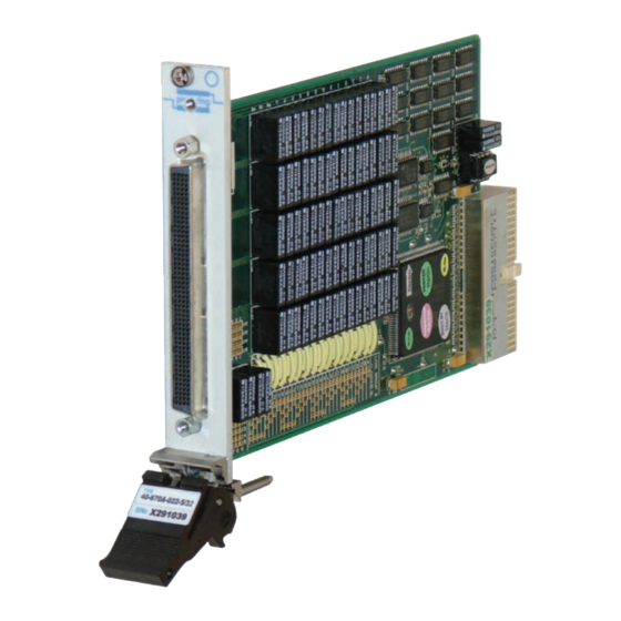
- Page 1 40-670A User Manual PXI Very High Density Multiplexer Module pickeringtest.com Issue 11.1 May 2023...
- Page 2 © COPYRIGHT (2023) PICKERING INTERFACES. ALL RIGHTS RESERVED. No part of this publication may be reproduced, transmitted, transcribed, translated or stored in any form, or by any means without the written permission of Pickering Interfaces. Technical details contained within this publication are subject to change without notice.
- Page 3 Pickering Interfaces strives to fulfil all relevant environmental laws and regulations and reduce wastes and releases to the environment. Pickering Interfaces aims to design and operate products in a way that protects the environment and the health and safety of its employees, customers and the public. Pickering Interfaces endeavours to develop and manufacture products that can be produced, distributed, used and recycled, or disposed of, in a safe and environmentally friendly manner.
-
Page 4: Product Safety
If this product is heavy reference should be made to the safety instructions for provisions of lifting and moving. STATIC SENSITIVE To indicate that static sensitive devices are present and handling precautions should be followed. REED RELAY MODULE 40-110/115/120/125 VERY HIGH DENSITY MULTIPLEXER MODULE 40-670A Page (IV) Page (IV) -
Page 5: Table Of Contents
Pre Operation Checks ............3.1 Hardware Installation ............3.2 Software Installation .............3.2 Testing Operation ..............3.3 Section 4 Programming Guide ..............4.1 Programming Options For Pickering PXI Modules ....4.1 Programming The Module ............4.2 Section 5 Connector Information ..............5.1 Section 6 Trouble Shooting .................6.1 Section 7 Maintenance Information ............7.1... - Page 6 THIS PAGE INTENTIONALLY BLANK VERY HIGH DENSITY MULTIPLEXER MODULE 40-670A Page (VI)
-
Page 7: Warnings And Cautions
Not to be used in safety critical circuits, refer to the Pickering Interfaces’ terms & conditions of sale. This module must not be used for the switching of Mains Circuits. For the switching of voltages up to the module’s full specification, Secondary Circuit power supplies and the Device Under Test must... - Page 8 • For suitably equipped products in the event of an emergency press the red “emergency stop” button situated on the front of the unit. VERY HIGH DENSITY MULTIPLEXER MODULE 40-670A Page (VIII) 2 AMP 1-POLE UHD MATRIX MODULES 40-575 / 576 / 577 / 578 / 579...
-
Page 9: Technical Specification
Supported by PXI or LXI Chassis y Supported by eBIRST ™ y 3 Year Warranty The 40-670A module features a wide range of multiplexer configurations based on high performance ruthenium reed relays. Typical applications include signal routing in ATE and data acquisition systems. - Page 10 10.2 10.3 10.4 10.5 10.6 10.7 10.8 5.25 10.9 5.26 10.10 5.27 10.11 5.28 10.12 5.29 10.13 5.30 10.14 5.31 10.15 5.32 10.16 40-670A-022 10-Channel 16-Pole Multiplexer 40-670A-022 5-Channel 32-Pole Multiplexer pickeringtest.com VERY HIGH DENSITY MULTIPLEXER MODULE 40-670A Page 1.2...
- Page 11 1340 mA (typ 300 mA) 40-670A-022 24-Channel 8-Pole Multiplexer Operating/Storage Conditions Relay Type Operating Conditions The 40-670A is fitted with ruthenium sputtered reed relays, Operating Temperature: 0 °C to +55 °C these offer very long life with good low level switching Humidity: Up to 90 % non-condensing performance and excellent contact resistance stability.
- Page 12 5-Channel, 16-Pole 40-670A-021-5/16 Multiple Mating Connectors & Cabling 99-Channel, 2-Pole 40-670A-022-99/2 Multiple 49-Channel, 4-Pole 40-670A-022-49/4 Multiple For connection accessories for the 40-670A range please Multiple 24-Channel, 8-Pole 40-670A-022-24/8 refer to the 90-002D 200-pin LFH Connector Accessories 10-Channel, 16-Pole 40-670A-022-10/16 Multiple...
- Page 13 We provide a full range of supporting cable and connector solutions for all our switching products—20 connector families with 1200+ products. We offer everything from simple mating connectors to complex cables assemblies and terminal blocks. All assemblies are manufactured by Pickering and are guaranteed to mechanically and electrically mate to our modules. Connectors & Backshells...
- Page 14 Very High Density Multiplexer, 40-670A Programming Pickering provide kernel, IVI and VISA (NI & Keysight) drivers which are compatible with all Microsoft supported versions of Windows and popular older versions. For a list of all supporting operating systems, please see: pickeringtest.com/os...
-
Page 15: Technical Description
SECTION 2 - TECHNICAL DESCRIPTION pickering SECTION 2 - TECHNICAL DESCRIPTION MECHANICAL DESCRIPTION The 40-670A range of multiplexer modules conform to the 3U height (128mm) Eurocard standard. Each module comprises: • CPCI ejector handle • Front panel mounted 200-pin female LFH connector •... -
Page 16: Functional Description
SECTION 2 - TECHNICAL DESCRIPTION pickering FUNCTIONAL DESCRIPTION Isolation Switch 40-670A -021-99/1 - 99-Channel, 1-Pole MUX Isolation Switch Com 1 Com 2 Com 3 Isolation Com 4 Switch Com 5 Com 1 Com 6 Com 2 Com 7 Com 8 99.1... - Page 17 5.28 10.14 5.29 10.15 5.30 10.16 5.31 5.32 40-670A -022-10/16 - 10-Channel, 16-Pole MUX 40-670A -022-5/32 - 5-Channel, 32-Pole MUX Figure 2.2 - Multiplexer Modules Capable of Multiple Channel Selection - Continued VERY HIGH DENSITY MULTIPLEXER MODULE 40-670A Page 2.3...
- Page 18 U8 TO U20 CONNECTOR PCI BRIDGE TERMINATING MODULE RESISTORS CONFIGURATION R4 TO R15 U5, U6 AND U7 PCI BRIDGE CONFIGURATION Figure 2.3 - Very High Density Multiplexer Module 40-670A: Functional Block Diagram VERY HIGH DENSITY MULTIPLEXER MODULE 40-670A Page 2.4...
-
Page 19: Installation
Modular products require installation in a suitable PXI/LXI chassis. The module is designed for indoor use only. PREOPERATION CHECKS (UNPACKING) 1. Check the module for transport damage and report any damage immediately to Pickering Interfaces. Do not attempt to install the product if any damage is evident. -
Page 20: Hardware Installation
For a system comprising more than one chassis, turn ON the last chassis in the system followed by the penultimate, etc, and finally turn ON the external controller or chassis containing the system controller. 9. For Pickering Interfaces modular LXI installation there is no requirement to use any particular power up sequence. -
Page 21: Testing Operation
Figure 3.2 - General Soft Front Panel Icon A selector panel will appear, listing all installed Pickering PCI, PXI or LXI switch cards and resistor cards. Click on the card you wish to control, and a graphical control panel is presented allowing operation of the card. - Page 22 SECTION 3 - INSTALLATION pickering THIS PAGE INTENTIONALLY BLANK VERY HIGH DENSITY MULTIPLEXER MODULE 40-670A Page 3.4...
-
Page 23: Programming Guide
SECTION 4 - PROGRAMMING GUIDE PROGRAMMING OPTIONS FOR PICKERING INTERFACES PXI MODULES For information on the installation and use of drivers and the programming of Pickering’s products in various software environments, please refer to the Software User Manual. This is available as a download from: https://www.pickeringtest.com/support/software-drivers-and-downloads... -
Page 24: Programming The Module
Once the drivers are installed the manual “Sys40Prg.pdf” and driver help files which fully describes these functions can be found in the Pickering folder(s) or the Pickering entries on your Start Menu. The card must be opened before use and closed after using the following function calls: IVI Driver: ViSession vi;... -
Page 25: Connector Information
SECTION 5 - CONNECTOR INFORMATION Isolation Switch 99 CHANNEL 1 POLE 40-670A-021-99/1 Figure 5.1 - Multiplexer Module: Pinouts - 99 Channel, 1 Pole (200-pin Female LFH Connector Viewed From Front of Module) VERY HIGH DENSITY MULTIPLEXER MODULE 40-670A Page 5.1... - Page 26 45.1 48.2 48.1 47.2 47.1 49.2 49.1 49 CHANNEL 2 POLE 40-670A-021-49/2 Figure 5.2 - Multiplexer Module: Pinouts - 49 Channel, 2 Pole (200-pin Female LFH Connector Viewed From Front of Module) VERY HIGH DENSITY MULTIPLEXER MODULE 40-670A Page 5.2...
- Page 27 23.3 23.2 23.1 24.4 24.3 24.2 24.1 24 CHANNEL 4 POLE 40-670A-021-24/4 Figure 5.3 - Multiplexer Module: Pinouts - 24 Channel, 4 Pole (200-pin Female LFH Connector Viewed From Front of Module) VERY HIGH DENSITY MULTIPLEXER MODULE 40-670A Page 5.3...
- Page 28 10.7 10.6 10.5 10.5 10.6 10.7 10.8 10 CHANNEL 8 POLE 40-670A-021-10/8 Figure 5.4 - Multiplexer Module: Pinouts - 10 Channel, 8 Pole (200-pin Female LFH Connector Viewed From Front of Module) VERY HIGH DENSITY MULTIPLEXER MODULE 40-670A Page 5.4...
- Page 29 5.10 5.11 5.12 5.13 5.14 5.15 5.16 5 CHANNEL 16 POLE 40-670A-021-5/16 Figure 5.5 - Multiplexer Module: Pinouts - 5 Channel, 16 Pole (200-pin Female LFH Connector Viewed From Front of Module) VERY HIGH DENSITY MULTIPLEXER MODULE 40-670A Page 5.5...
- Page 30 SECTION 5 - CONNECTOR INFORMATION pickering Isolation Switch 198 CHANNEL 1 POLE 40-670A-022-198/1 Figure 5.6 - Multiplexer Module: Pinouts - 198 Channel, 1 Pole (200-pin Female LFH Connector Viewed From Front of Module) VERY HIGH DENSITY MULTIPLEXER MODULE 40-670A Page 5.6...
- Page 31 93.2 99.1 98.1 97.1 99.2 98.2 97.2 99 CHANNEL 2 POLE 40-670A-022-99/2 Figure 5.7 - Multiplexer Module: Pinouts - 99 Channel, 2 Pole (200-pin Female LFH Connector Viewed From Front of Module) VERY HIGH DENSITY MULTIPLEXER MODULE 40-670A Page 5.7...
- Page 32 48.2 47.4 47.2 49.3 49.1 49.4 49.2 49 CHANNEL 4 POLE 40-670A-022-49/4 Figure 5.8 - Multiplexer Module: Pinouts - 49 Channel, 4 Pole (200-pin Female LFH Connector Viewed From Front of Module) VERY HIGH DENSITY MULTIPLEXER MODULE 40-670A Page 5.8...
- Page 33 24.5 24.3 24.1 24.8 24.6 24.4 24.2 24 CHANNEL 8 POLE 40-670A-022-24/8 Figure 5.9 - Multiplexer Module: Pinouts - 24 Channel, 8 Pole (200-pin Female LFH Connector Viewed From Front of Module) VERY HIGH DENSITY MULTIPLEXER MODULE 40-670A Page 5.9...
- Page 34 DUAL 10 CHANNEL 8 POLE 210.6 210.7 40-670A-022-D/10/8 210.8 Figure 5.10 - Multiplexer Module: Pinouts - Dual 10 Channel, 8 Pole (Special Build) (200-pin Female LFH Connector Viewed From Front of Module) VERY HIGH DENSITY MULTIPLEXER MODULE 40-670A Page 5.10...
- Page 35 10.10 10.11 10.12 10.13 10.14 10.15 10.16 10 CHANNEL 16 POLE 40-670A-022-10/16 Figure 5.11 - Multiplexer Module: Pinouts - 10 Channel, 16 Pole (200-pin Female LFH Connector Viewed From Front of Module) VERY HIGH DENSITY MULTIPLEXER MODULE 40-670A Page 5.11...
- Page 36 5.26 5.27 5.28 5.29 5.30 5.31 5.32 5 CHANNEL 32 POLE 40-670A-022-5/32 Figure 5.12 - Multiplexer Module: Pinouts - 5 Channel, 32 Pole (200-pin Female LFH Connector Viewed From Front of Module) VERY HIGH DENSITY MULTIPLEXER MODULE 40-670A Page 5.12...
- Page 37 48.2 48.1 47.2 47.1 49.2 49.1 49 CHANNEL 2 POLE 40-670A-021-S-49/2 Figure 5.13 - Multiplexer Module: Pinouts - 49 Channel, 2 Pole, Screened (200-pin Female LFH Connector Viewed From Front of Module) VERY HIGH DENSITY MULTIPLEXER MODULE 40-670A Page 5.13...
- Page 38 5.15 5.14 5.13 5.14 5.15 5.16 5 CHANNEL 16 POLE 40-670A-021-S-5/16 Figure 5.14 - Multiplexer Module: Pinouts - 5 Channel, 16 Pole, Screened (200-pin Female LFH Connector Viewed From Front of Module) VERY HIGH DENSITY MULTIPLEXER MODULE 40-670A Page 5.14...
-
Page 39: Trouble Shooting
PCI configuration, highlighting any potential configuration problems. Specific details of all installed Pickering switch cards are included. All the installed Pickering switch cards should be listed in the “Pilpxi information” section - if one or more cards is missing it may be possible to determine the reason by referring to the PCI configuration dump contained in the report, but interpretation of this information is far from straightforward, and the best course is to contact Pickering support: support@pickeringtest.com, if possible... - Page 40 SECTION 6 - TROUBLE SHOOTING pickering THIS PAGE INTENTIONALLY BLANK VERY HIGH DENSITY MULTIPLEXER MODULE 40-670A Page 6.2...
-
Page 41: Maintenance Information
For PXI modules which are supported in one of Pickering Interfaces’ Modular LXI Chassis (such as the 60-102B and 60-103B) no module software update is required. If the module was introduced after the LXI chassis was manufactured the module may not be recognized, in this case the chassis firmware may need upgrading. - Page 42 SECTION 7 - MAINTENANCE INFORMATION pickering Table 7.1: 40-670A-022-198/1 (198 Channel, 1-Pole) Configuration Logical Physical Logical Physical Function Function Channel Number Channel Number Channel 1 Pole 1 Channel 51 Pole 1 Channel 2 Pole 1 Channel 52 Pole 1 Channel 3...
- Page 43 SECTION 7 - MAINTENANCE INFORMATION pickering Table 7.1: 40-670A-022-198/1 (198 Channel, 1-Pole) Configuration (continued) Logical Physical Logical Physical Function Function Channel Number Channel Number Channel 151 Pole 1 Channel 101 Pole 1 Channel 152 Pole 1 Channel 102 Pole 1...
- Page 44 SECTION 7 - MAINTENANCE INFORMATION pickering Table 7.2: 40-670A-021-99/1 (99 Channel, 1-Pole) Configuration Logical Physical Logical Physical Function Function Channel Number Channel Number Channel 1 Pole 1 Channel 51 Pole 1 Channel 2 Pole 1 Channel 52 Pole 1 Channel 53...
- Page 45 SECTION 7 - MAINTENANCE INFORMATION pickering Table 7.3: 40-670A-022-99/2 (99 Channel, 2-Pole) Configuration Logical Physical Logical Physical Function Function Channel Number Channel Number Channel 1 Poles 1&2 Channel 51 Poles 1&2 Channel 2 Poles 1&2 Channel 52 Poles 1&2 Channel 53 Poles 1&2...
- Page 46 SECTION 7 - MAINTENANCE INFORMATION pickering Table 7.4: 40-670A-021-49/2 (49 Channel, 2-Pole) Configuration Logical Physical Logical Physical Function Function Channel Number Channel Number Channel 1 Pole 1 Channel 26 Pole 1 Channel 1 Pole 2 Channel 26 Pole 2 Channel 27...
- Page 47 SECTION 7 - MAINTENANCE INFORMATION pickering Table 7.5: 40-670A-022-49/4 (49 Channel, 4-Pole) Configuration Logical Physical Logical Physical Function Function Channel Number Channel Number Channel 1 Pole 1&2 Channel 26 Pole 1&2 Channel 1 Pole 3&4 Channel 26 Pole 3&4 Channel 2 Pole 1&2...
- Page 48 SECTION 7 - MAINTENANCE INFORMATION pickering Table 7.6: 40-670A-021-24/4 (24 Channel, 4-Pole) Configuration Logical Physical Logical Physical Function Function Channel Number Channel Number Channel 1 Pole 1 Channel 13 Pole 3 Channel 1 Pole 2 Channel 13 Pole 4 Channel 1...
- Page 49 SECTION 7 - MAINTENANCE INFORMATION pickering Table 7.7: 40-670A-022-24/8 (24 Channel, 8-Pole) Configuration Logical Physical Logical Physical Function Function Channel Number Channel Number Channel 1 Pole 1&2 Channel 13 Pole 5&6 Channel 1 Pole 3&4 Channel 13 Pole 7&8 Channel 14 Pole 1&2...
- Page 50 SECTION 7 - MAINTENANCE INFORMATION pickering Table 7.8: 40-670A-021-10/8 (10 Channel, 8-Pole) Configuration Logical Physical Logical Physical Function Function Channel Number Channel Number Channel 7 Pole 3 Channel 1 Pole 1 Channel 7 Pole 4 Channel 1 Pole 2 Channel 1...
- Page 51 SECTION 7 - MAINTENANCE INFORMATION pickering Table 7.9: 40-670A-022-10/16 (10 Channel, 16-Pole) Configuration Logical Physical Logical Physical Function Function Channel Number Channel Number Channel 1 Pole 1&2 Channel 7 Pole 5&6 Channel 1 Pole 3&4 Channel 7 Pole 7&8 Channel 1 Pole 5&6...
- Page 52 SECTION 7 - MAINTENANCE INFORMATION pickering Table 7.10: 40-670A-021-5/16 (5 Channel, 16-Pole) Configuration Logical Physical Logical Physical Function Function Channel Number Channel Number Channel 1 Pole 1 Channel 4 Pole 3 Channel 1 Pole 2 Channel 4 Pole 4 Channel 4...
- Page 53 SECTION 7 - MAINTENANCE INFORMATION pickering Table 7.11: 40-670A-022-5/32 (5 Channel, 32-Pole) Configuration Logical Physical Logical Physical Function Function Channel Number Channel Number Channel 1 Pole 1&2 Channel 4 Pole 5&6 Channel 1 Pole 3&4 Channel 4 Pole 7&8 Channel 4 Pole 9&10...
- Page 54 RL94 RL78 RL62 RL46 RL30 RL14 RL95 RL79 RL63 RL47 RL31 RL15 RL96 RL80 RL64 RL48 RL32 RL16 RL100 RL99 pickering RL98 RL97 RL97a Figure 7.1 - 40-670A Multiplexer Module: Component Layout VERY HIGH DENSITY MULTIPLEXER MODULE 40-670A Page 7.14...
Need help?
Do you have a question about the 40-670A and is the answer not in the manual?
Questions and answers