
Related Manuals for Pickering 40-292


Summary of Contents for Pickering 40-292
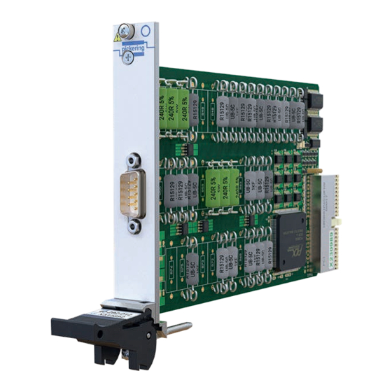
- Page 1 40-292 User Manual PXI Load Resistor Module pickeringtest.com Issue 2.2 January 2020...
- Page 2 © COPYRIGHT (2020) PICKERING INTERFACES. ALL RIGHTS RESERVED. No part of this publication may be reproduced, transmitted, transcribed, translated or stored in any form, or by any means without the written permission of Pickering Interfaces. Technical details contained within this publication are subject to change without notice.
- Page 3 Pickering Interfaces strives to fulfil all relevant environmental laws and regulations and reduce wastes and releases to the environment. Pickering Interfaces aims to design and operate products in a way that protects the environment and the health and safety of its employees, customers and the public. Pickering Interfaces endeavours to develop and manufacture products that can be produced, distributed, used and recycled, or disposed of, in a safe and environmentally friendly manner.
-
Page 4: Product Safety
If this product is heavy reference should be made to the safety instructions for provisions of lifting and moving. STATIC SENSITIVE To indicate that static sensitive devices are present and handling precautions should be followed. REED RELAY MODULE 40-110/115/120/125 LOAD RESISTOR MODULE 40-292 Page (IV) Page (IV) -
Page 5: Table Of Contents
Hardware Installation ............3.2 Software Installation .............3.2 Testing Operation ..............3.3 Section 4 Programming Guide ..............4.1 Programming Options For Pickering PXI Modules ....4.1 Module Architecture - 40-292-011 ........4.2 Module Architecture - 40-292-012 ........4.3 Programming The Module ............4.4 Section 5 Connector Information ..............5.1 Section 6 Trouble Shooting .................6.1... - Page 6 THIS PAGE INTENTIONALLY BLANK LOAD RESISTOR MODULE 40-292 Page (VI)
-
Page 7: Warnings And Cautions
Not to be used in safety critical circuits, refer to the Pickering Interfaces’ terms & conditions of sale. This module must not be used for the switching of Mains Circuits. For the switching of voltages up to the module’s full specification, Secondary Circuit power supplies and the Device Under Test must... - Page 8 • For suitably equipped products in the event of an emergency press the red “emergency stop” button situated on the front of the unit. LOAD RESISTOR MODULE 40-292 Page (VIII) 2 AMP 1-POLE UHD MATRIX MODULES 40-575 / 576 / 577 / 578 / 579...
-
Page 9: Technical Specification
The 40-292 provides a simple solution for applications requiring a programmable load resistor with up to 15W power handling. The 40-292 module is able to simulate the common short circuit and open circuit conditions that can be experienced in a system due to faulty wiring or sensors. - Page 10 SECTION 1 - TECHNICAL SPECIFICATION pickering Specifications Load Resistor Module – 40-292 Mechanical Characteristics Specification Single slot 3U PXI (CompactPCI card). Resistance Channels 3D models for all versions in a variety of popular file formats are available on request. Model Number...
- Page 11 Lowest Resistance † Mating Connectors & Cabling Highest Resistance For connection accessories for the 40-292 series please refer Resistance Resolution to the 90-003D 9-pin D-Type Connector Accessories data sheet where a complete list and documentation can be found for Overall Accuracy accessories, or refer to the Connection Solutions catalog.
- Page 12 We provide a full range of supporting cable and connector solutions for all our switching products—20 connector families with 1200+ products. We offer everything from simple mating connectors to complex cables assemblies and terminal blocks. All assemblies are manufactured by Pickering and are guaranteed to mechanically and electrically mate to our modules. Connectors & Backshells...
- Page 13 Load Resistor Module – 40-292 Programming Pickering provide kernel, IVI and VISA (NI & Keysight) drivers which are compatible with all Microsoft supported versions of Windows and popular older versions. For a list of all supporting operating systems, please see: pickeringtest.com/os...
- Page 14 SECTION 1 - TECHNICAL SPECIFICATION pickering THIS PAGE INTENTIONALLY BLANK LOAD RESISTOR MODULE 40-292 Page 1.6...
-
Page 15: Functional Description
R1 TO R12 OFFSET U9 TO RESISTORS BRIDGE CONTROL LOGIC U2 TO U6 SOLID STATE RELAYS U14 to U21 MODULE PCI BRIDGE CONFIGURATION CONFIGURATION Figure 2.1 - Load Resistor Module 40-292: Functional Block Diagram LOAD RESISTOR MODULE 40-292 Page 2.1... -
Page 16: Guidance On Using The Module
Figure 2.2 - 40-292-011 and 40-292-012 Load Resistor Modules - Pin Naming Cooling and Chassis Considerations In use, the 40-292 Resistor Module can dissipate a high level of power into the host chassis. When using the 40-292, especially if multiple modules are fitted to a chassis, users should: If the chassis supports speed controlled fans it is recommended that the speed of these fans is set to maximum rather than left under automatic control. -
Page 17: Installation
Modular products require installation in a suitable PXI/LXI chassis. The module is designed for indoor use only. PREOPERATION CHECKS (UNPACKING) 1. Check the module for transport damage and report any damage immediately to Pickering Interfaces. Do not attempt to install the product if any damage is evident. -
Page 18: Hardware Installation
For a system comprising more than one chassis, turn ON the last chassis in the system followed by the penultimate, etc, and finally turn ON the external controller or chassis containing the system controller. 9. For Pickering Interfaces modular LXI installation there is no requirement to use any particular power up sequence. -
Page 19: Testing Operation
Figure 3.2 - General Soft Front Panel Icon A selector panel will appear, listing all installed Pickering PCI, PXI or LXI switch cards and resistor cards. Click on the card you wish to control, and a graphical control panel is presented allowing operation of the card. - Page 20 SECTION 3 - INSTALLATION pickering THIS PAGE INTENTIONALLY BLANK LOAD RESISTOR MODULE 40-292 Page 3.4...
-
Page 21: Programming Guide
SECTION 4 - PROGRAMMING GUIDE PROGRAMMING OPTIONS FOR PICKERING INTERFACES PXI MODULES For information on the installation and use of drivers and the programming of Pickering’s products in various software environments, please refer to the Software User Manual. This is available as a download from: https://www.pickeringtest.com/support/software-drivers-and-downloads... -
Page 22: Module Architecture - 40-292-011
Figure 4.1 - 40-292-011 Load Resistor Module Architecture The 40-292-011 Load Resistor Module is programmed using two sub-units, one to control the 8 resistor chain switches and one for the short circuit and isolation switches as show in the table below:... -
Page 23: Module Architecture - 40-292-012
Figure 4.1 - 40-292-012 Load Resistor Module Architecture The 40-292-012 Load Resistor Module is programmed using two sub-units, one to control the 8 resistor chain switches and one for the short circuit and isolation switches as show in the table below:... -
Page 24: Programming The Module
SECTION 4 - PROGRAMMING GUIDE pickering PROGRAMMING THE MODULE Here are examples of using the drivers with the 40-292 Using PILPXI To operate a relay the user could use the simple OpBit command or the WriteSub commands OpBit DWORD sub_unit = 1;... - Page 25 Output 1 (-) Input 4 (+) Output 1 (-) Input 5 (+) FP_GND Figure 5.1 - Pinouts: Load Resistor Module - 9-pin male D-type viewed from front of module (See Figure 2.2 For Pin Naming Assignments) LOAD RESISTOR MODULE 40-292 Page 5.1...
- Page 26 SECTION 5 - CONNECTOR INFORMATION pickering THIS PAGE INTENTIONALLY BLANK LOAD RESISTOR MODULE 40-292 Page 5.2...
-
Page 27: Trouble Shooting
PCI configuration, highlighting any potential configuration problems. Specific details of all installed Pickering switch cards are included. All the installed Pickering switch cards should be listed in the “Pilpxi information” section - if one or more cards is missing it may be possible to determine the reason by referring to the PCI configuration dump contained in the report, but interpretation of this information is far from straightforward, and the best course is to contact Pickering support: support@pickeringtest.com, if possible... - Page 28 SECTION 6 - TROUBLE SHOOTING pickering THIS PAGE INTENTIONALLY BLANK LOAD RESISTOR MODULE 40-292 Page 6.2...
-
Page 29: Maintenance Information
For PXI modules which are supported in one of Pickering Interfaces’ Modular LXI Chassis (such as the 60-102B and 60-103B) no module software update is required. If the module was introduced after the LXI chassis was manufactured the module may not be recognized, in this case the chassis firmware may need upgrading. - Page 30 SECTION 7 - MAINTENANCE INFORMATION pickering 40-292-011 RELAY CROSS REFERENCE Relay Function Resistor Chain Bit 8 (128Ω) U14A Resistor Chain Bit 7 (64Ω) U14B Resistor Chain Bit 6 (32Ω) U15A Resistor Chain Bit 5 (16Ω) U15B Resistor Chain Bit 4 (8Ω) U16A Resistor Chain Bit 3 (4Ω)
- Page 31 SECTION 7 - MAINTENANCE INFORMATION pickering Figure 7.1 - 40-292 Load Resistor Component Layout LOAD RESISTOR MODULE 40-292 Page 7.3...
- Page 32 SECTION 7 - MAINTENANCE INFORMATION pickering THIS PAGE INTENTIONALLY BLANK LOAD RESISTOR MODULE 40-292 Page 7.4...
Need help?
Do you have a question about the 40-292 and is the answer not in the manual?
Questions and answers