
Related Manuals for Pickering PXI BRIC 40-595A


Summary of Contents for Pickering PXI BRIC 40-595A
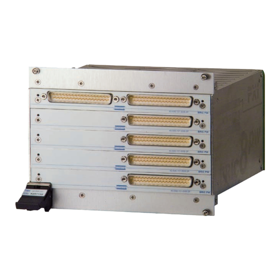
- Page 1 40-595A User Manual PXI BRIC™ Power FIBO Matrix Module pickeringtest.com Issue 3.6 February 2020...
- Page 2 © COPYRIGHT (2020) PICKERING INTERFACES. ALL RIGHTS RESERVED. No part of this publication may be reproduced, transmitted, transcribed, translated or stored in any form, or by any means without the written permission of Pickering Interfaces. Technical details contained within this publication are subject to change without notice.
- Page 3 Pickering Interfaces strives to fulfil all relevant environmental laws and regulations and reduce wastes and releases to the environment. Pickering Interfaces aims to design and operate products in a way that protects the environment and the health and safety of its employees, customers and the public. Pickering Interfaces endeavours to develop and manufacture products that can be produced, distributed, used and recycled, or disposed of, in a safe and environmentally friendly manner.
-
Page 4: Product Safety
PRODUCT SAFETY SAFETY SYMBOLS The following safety symbols may be used on the product and throughout the product documentation. MEANING / DESCRIPTION SYMBOL PROTECTIVE EARTH (GROUND) To identify any terminal which is intended for connection to an external conductor for protection against electric shock in case of a fault, or the terminal of a protective earth (ground) electrode. -
Page 5: Table Of Contents
Programming Guide ..............4.1 Programming Options for PXI Modules ......4.1 Module Architecture ..............4.2 Using The Module Under IVI ..........4.3 Programming The Module ............4.4 Using Pickering Drivers in LabVIEW ........4.8 Section 5 Connector Information ..............5.1 Section 6 Trouble Shooting .................6.1 Section 7 Maintenance Information ............7.1... - Page 6 THIS PAGE INTENTIONALLY BLANK BRIC POWER FIBO MATRIX MODULE (40-595A) Page (VI)
-
Page 7: Warnings And Cautions
Not to be used in safety critical circuits, refer to the Pickering Interfaces’ terms & conditions of sale. This module must not be used for the switching of Mains Circuits. For the switching of voltages up to the module’s full specification, Secondary Circuit power supplies and the Device Under Test must... - Page 8 CAUTION - PRODUCT DOCUMENTATION SYMBOL Suitably qualified & trained users should ensure that the accompanying documentation is fully read and understood before attempting to install or operate the product. SAFETY INSTRUCTIONS SAFETY INSTRUCTIONS All cleaning and servicing requires the equipment to be isolated and disconnected from the power source and user I/O signals (refer to the Maintenance Section).
- Page 9 SECTION 1 - TECHNICAL SPECIFICATION pickering PXI BRIC™ Power FIBO Matrix 40-595A SECTION 1 - TECHNICAL SPECIFICATION • Integrated High Power PXI Matrix Module • Built In High Performance Screened 8-Channel Analog Bus • 3-Pin Breakout Configuration For Fault Simulation and Specialist Test Applications •...
- Page 10 SECTION 1 - TECHNICAL SPECIFICATION pickering Specifications BRIC Power FIBO Matrix – 40-595A Relay Type The 40-595A is fitted with single-pole electro-mechanical power AC Resistive relays, gold-flash over silver alloy contact. Switching Specification - Crosspoint Relays AC Inductive Contact Type:...
- Page 11 SECTION 1 - TECHNICAL SPECIFICATION Specifications pickering BRIC Power FIBO Matrix – 40-595A Width and Dimensions Operating/Storage Conditions Eight slot 3U PXI module (CompactPCI). Operating Conditions Operating Temperature: 0°C to +55°C 3D models for these modules in a variety of popular file formats are...
- Page 12 Product Customization Pickering PXI modules are designed and manufactured on our own flexible manufacturing lines, giving complete product control and enabling simple customization to meet very specific requirements. Customization can include: •...
- Page 13 We provide a full range of supporting cable and connector solutions for all our switching products—20 connector families with 1200+ products. We offer everything from simple mating connectors to complex cables assemblies and terminal blocks. All assemblies are manufactured by Pickering and are guaranteed to mechanically and electrically mate to our modules. Connectors & Backshells...
-
Page 14: Technical Specification
BRIC Power FIBO Matrix – 40-595A Programming Pickering provide kernel, IVI and VISA (NI & Keysight) drivers which are compatible with all Microsoft supported versions of Windows and popular older versions. For a list of all supporting operating systems, please see: pickeringtest.com/os... -
Page 15: Technical Description
SECTION 2 - TECHNICAL DESCRIPTION pickering SECTION 2 - TECHNICAL DESCRIPTION MECHANICAL DESCRIPTION The Power FIBO BRIC Module comprises an alloy chassis, 8 PXI slot width, with an integral backplane and a 1 to 5 horizontally mounted Matrix Daughter Cards. The chassis is provided with cooling slots, top and bottom. The backplane provides mounting for the 50-pin connectors (into which the Matrix Daughter Cards plug) and the PXI interface and control logic. -
Page 16: Functional Description
SECTION 2 - TECHNICAL DESCRIPTION pickering FUNCTIONAL DESCRIPTION A functional block diagram is provided in Figure 2.2. The BRIC Module is powered by a +5V input via Compact PCI connector J1 mounted on the Backplane. The interface to the user test equipment is via the front panel mounted 37-pin D-type connectors, mounted on the Matrix Daughter boards. -
Page 17: Maximum Frequency Of Operations At Full Load
SECTION 2 - TECHNICAL DESCRIPTION pickering MAXIMUM FREQUENCY OF OPERATIONS AT FULL LOAD At full load breaking contacts can create a significant amount thermal load inside the relays by the generation of strong signal arcs. If the relays are operated near full load then the rate of operations (a complete on and off cycle) should be limited to a repetition rate of 0.3Hz to avoid the resulting heat damaging the relay plastic components. - Page 18 SECTION 2 - TECHNICAL DESCRIPTION pickering Simulator A Fault Insertion Break-Out Module 40-595A-010 X1.2 X1.1 X1.3 X2.2 X2.1 X2.3 X30.2 X30.1 X30.3 Y1.1 Y2.1 Simulator B Y1.2 Y2.2 Y1.3 Y2.3 Y1.4 Y2.4 30x4 Fault Matrix - Bank 1 30x4 Fault Matrix - Bank 2 Fault Insertion Example: Short Between Break-Out 1 &...
- Page 19 SECTION 2 - TECHNICAL DESCRIPTION pickering Simulator A Fault Insertion Break-Out Module 40-595A-010 X1.2 X1.1 X1.3 X2.2 X2.1 X2.3 X30.2 X30.1 X30.3 Y1.1 Y2.1 Simulator B Y1.2 Y2.2 Y1.3 Y2.3 Y1.4 Y2.4 30x4 Fault Matrix - Bank 1 30x4 Fault Matrix - Bank 2...
- Page 20 SECTION 2 - TECHNICAL DESCRIPTION pickering Fault Insertion Break-Out Module 40-595A-010 X1.2 X1.1 X1.3 X2.2 X2.1 X2.3 Simulator X30.2 X30.1 X30.3 Y1.1 Y2.1 Y1.2 Y2.2 Y1.3 Y2.3 Y1.4 Y2.4 30x4 Fault Matrix - Bank 1 30x4 Fault Matrix - Bank 2 Fault Insertion Example: Adding Series Resistance Into Break-Out 1 Using 1.3...
-
Page 21: Installation
Modular products require installation in a suitable PXI/LXI chassis. The module is designed for indoor use only. PREOPERATION CHECKS (UNPACKING) 1. Check the module for transport damage and report any damage immediately to Pickering Interfaces. Do not attempt to install the product if any damage is evident. -
Page 22: Hardware Installation
For a system comprising more than one chassis, turn ON the last chassis in the system followed by the penultimate, etc, and finally turn ON the external controller or chassis containing the system controller. 9. For Pickering Interfaces modular LXI installation there is no requirement to use any particular power up sequence. -
Page 23: Testing Operation
Figure 3.2 - General Soft Front Panel Icon A selector panel will appear, listing all installed Pickering PCI, PXI or LXI switch cards and resistor cards. Click on the card you wish to control, and a graphical control panel is presented allowing operation of the card. - Page 24 SECTION 3 - INSTALLATION pickering THIS PAGE INTENTIONALLY BLANK BRIC POWER FIBO MATRIX MODULE (40-595A) Page 3.4...
-
Page 25: Programming Guide
SECTION 4 - PROGRAMMING PROGRAMMING OPTIONS FOR PICKERING INTERFACES PXI MODULES For information on the installation and use of drivers and the programming of Pickering’s products in various software environments, please refer to the Software User Manual. This is available as a download from: https://www.pickeringtest.com/support/software-drivers-and-downloads... -
Page 26: Module Architecture
SECTION 4 - PROGRAMMING GUIDE pickering MODULE ARCHITECTURE The Following description applies to the 40-595A-009 (Dual 24x4 FIBO Matrix with 3-pin Breakout) other modules in the 40-595A range have the same architecture, but with different numbers of bits in the controlling sub-units. -
Page 27: Using The Module Under Ivi
SECTION 4 - PROGRAMMING GUIDE pickering USING THE MODULE UNDER IVI Figure 4.2 below displays the IVI channel names for the 40-595A-009 (Dual 24x4 FIBO Matrix with 3-pin Breakout) ncD1 ComC1 ncC1 ComD1 X1.2 X1.1 noD1 X1.3 ncD2 ComC2 ncC2 ComD2 X2.2... -
Page 28: Programming The Module
Once the drivers are installed the manual “Sys40Prg.pdf” and driver help files which fully describe these functions can be found in the Pickering folder(s) or the Pickering entries on your Start Menu. The card must be opened before use and closed after using the following function calls: Direct I/O Driver - Open with PIL_OpenCards or PIL_OpenSpecifiedCard and close with PIL_CloseCards or PIL_ CloseSpecifiedCards respectively. - Page 29 SECTION 4 - PROGRAMMING GUIDE pickering WriteSub This will setup the card for “Fault Insertion Example 2” described in the “Technical Description” section of this manual. DWORD OutSub; //Starting with switches in default positions DWORD Data[4]; //Assuming a 30x4 matrix = 120 bits requires 4 x //DWORDS (each 32 bits) OutSub = 3;...
- Page 30 SECTION 4 - PROGRAMMING GUIDE pickering Using PIPX40 setChannelState ViUInt32 OutSub; //Starting with switches in default //positions OutSub = 3; //Select isolation switches pipx40_SetChannelState(vi, OutSub, 1, VI_ON); //Open isolation switch / Disconnect //X1.1 from X1.2 pipx40_SetChannelState(vi, OutSub, 1, VI_OFF); //Close isolation switch again / //Reconnect X1.1 to X1.2...
- Page 31 SECTION 4 - PROGRAMMING GUIDE pickering Using PI40IV //Starting with switches in default //positions pi40iv_Connect(vi, “comC1”,”chC1”); //Open isolation switch / Disconnect X1.1 //from X1.2 pi40iv_Disconnect(vi, “comC1”,”chC1”); //Close isolation switch again / Reconnect //X1.1 to X1.2 pi40iv_Connect(vi, “xA1”,”yA1”); //1st Matrix - Connect Y1.1 to X1.1 &...
-
Page 32: Using Pickering Drivers In Labview
USING PICKERING DRIVERS IN LabVIEW Most Pickering drivers include a LabVIEW wrapper to permit full operation of the Pickering product from the LabVIEW environment. These wrappers are normally installed to the current LabVIEW folder system during installation of the Pickering driver. -
Page 33: Connector Information
SECTION 5 - CONNECTOR INFORMATION pickering SECTION 5 - CONNECTOR INFORMATION Y Connections: Matrix Bank 1 - Y1.1 to Y1.4 Matrix Bank 2 - Y2.1 to Y2.4 X1.1 to X6.3 Daughter- board 1 X7.1 to X12.3 Daughter- board 2 X13.1 to X18.3... - Page 34 SECTION 5 - CONNECTOR INFORMATION pickering 10 11 12 13 14 15 16 17 18 19 20 21 22 23 24 25 26 27 28 29 30 31 32 33 34 35 36 37 Pin No. Signal Name Pin No.
- Page 35 SECTION 5 - CONNECTOR INFORMATION pickering 10 11 12 13 14 15 16 17 18 19 20 21 22 23 24 25 26 27 28 29 30 31 32 33 34 35 36 37 Pin No. Signal Name Pin No.
- Page 36 SECTION 5 - CONNECTOR INFORMATION pickering 10 11 12 13 14 15 16 17 18 19 20 21 22 23 24 25 26 27 28 29 30 31 32 33 34 35 36 37 Pin No. Signal Name Pin No.
-
Page 37: Trouble Shooting
PCI configuration, highlighting any potential configuration problems. Specific details of all installed Pickering switch cards are included. All the installed Pickering switch cards should be listed in the “Pilpxi information” section - if one or more cards is missing it may be possible to determine the reason by referring to the PCI configuration dump contained in the report, but interpretation of this information is far from straightforward, and the best course is to contact Pickering support: support@pickeringtest.com, if possible... - Page 38 SECTION 6 - TROUBLE SHOOTING pickering THIS PAGE INTENTIONALLY BLANK BRIC POWER FIBO MATRIX MODULE (40-595A) Page 6.2...
-
Page 39: Maintenance Information
For PXI modules which are supported in one of Pickering Interfaces’ Modular LXI Chassis (such as the 60-102B and 60-103B) no module software update is required. If the module was introduced after the LXI chassis was manufactured the module may not be recognized, in this case the chassis firmware may need upgrading. - Page 40 SECTION 7 - MAINTENANCE INFORMATION pickering TABLE 7.1 - 40-595A Daughterboard 1 Relay Look-Up Table Function Relay no. Function Relay no. Function Relay no. Breakout X1.1 Breakout X3.1 RL22 Breakout X5.1 RL42 Breakout X1.2/1.3 Breakout X3.2/3.3 RL21 Breakout X5.2/5.3 RL41 Crosspoint X1,Y1.1...
- Page 41 SECTION 7 - MAINTENANCE INFORMATION pickering TABLE 7.3 - 40-595A Daughterboard 3 Relay Look-Up Table Function Relay no. Function Relay no. Function Relay no. Breakout X13.1 Breakout X15.1 RL22 Breakout X17.1 RL42 Breakout X13.2/13.3 Breakout X15.2/15.3 RL21 Breakout X17.2/17.3 RL41 Crosspoint X13,Y1.1...
- Page 42 SECTION 7 - MAINTENANCE INFORMATION pickering TABLE 7.5 - 40-595A Daughterboard 5 Relay Look-Up Table Function Relay no. Function Relay no. Function Relay no. Breakout X25.1 Breakout X27.1 RL22 Breakout X29.1 RL42 Breakout X25.2/25.3 Breakout X27.2/27.3 RL21 Breakout X29.2/29.3 RL41 Crosspoint X25,Y1.1...
-
Page 43: Card Removal From Bric
SECTION 7 - MAINTENANCE INFORMATION pickering CARD REMOVAL FROM BRIC The following procedure is for the extraction of a matrix relay card from the 40-595A BRIC module. The steps shown are for a BRIC with vertical cards but extracting the horizontal cards fitted to the 40-595A is basically the same. The card extraction handle supplied with the module is required for this process as shown in Figure 7.3. - Page 44 SECTION 7 - MAINTENANCE INFORMATION pickering 3. Fit the card extraction handle over the connector of the relay card to be removed as shown in Figure 7.5. In the case of the 40-595A, fit the extraction handle to the connector on the right hand side of the relay card’s front panel.
-
Page 45: Card Replacement
SECTION 7 - MAINTENANCE INFORMATION pickering CARD REPLACEMENT CAUTION THE BACKPLANE CONNECTORS ARE NOT PROVIDED WITH LOCATING GUIDES. IN THE FOLLOWING PROCEDURE IS IT IMPORTANT THAT THE RELAY CARD CONNECTOR IS ALIGNED WITH THE BACKPLANE CONNECTOR BEFORE THE MODULE IS PUSHED FULLY HOME. - Page 46 SECTION 7 - MAINTENANCE INFORMATION pickering THIS PAGE INTENTIONALLY BLANK BRIC POWER FIBO MATRIX MODULE (40-595A) Page 7.8...
Need help?
Do you have a question about the PXI BRIC 40-595A and is the answer not in the manual?
Questions and answers