
Subscribe to Our Youtube Channel
Related Manuals for Pickering 40-580


Summary of Contents for Pickering 40-580
- Page 1 40-580/582/583 User Manual PXI 2 Amp 2-Pole High Density Matrix Modules pickeringtest.com Issue 2.5 August 2023...
- Page 2 © COPYRIGHT (2023) PICKERING INTERFACES. ALL RIGHTS RESERVED. No part of this publication may be reproduced, transmitted, transcribed, translated or stored in any form, or by any means without the written permission of Pickering Interfaces. Technical details contained within this publication are subject to change without notice.
- Page 3 Pickering Interfaces strives to fulfil all relevant environmental laws and regulations and reduce wastes and releases to the environment. Pickering Interfaces aims to design and operate products in a way that protects the environment and the health and safety of its employees, customers and the public. Pickering Interfaces endeavours to develop and manufacture products that can be produced, distributed, used and recycled, or disposed of, in a safe and environmentally friendly manner.
-
Page 4: Product Safety
If this product is heavy reference should be made to the safety instructions for provisions of lifting and moving. STATIC SENSITIVE To indicate that static sensitive devices are present and handling precautions should be followed. REED RELAY MODULE 40-110/115/120/125 2 AMP 2-POLE HIGH DENSITY MATRIX MODULES 40-580/582/583 Page (IV) Page (IV) -
Page 5: Table Of Contents
Using IVI Driver, Direct I/O Driver or VISA Driver ....4.3 Section 5 Connector Information ..............5.1 Section 6 Troubleshooting ................6.1 Section 7 Maintenance Information ............7.1 Switching System Test Tools ..........7.1 Relay Look-Up Tables ............7.1 2 AMP 2-POLE HIGH DENSITY MATRIX MODULES 40-580/582/583 Page (V) - Page 6 THIS PAGE INTENTIONALLY BLANK 2 AMP 2-POLE HIGH DENSITY MATRIX MODULES 40-580/582/583 Page (VI)
-
Page 7: Warnings And Cautions
Not to be used in safety critical circuits, refer to the Pickering Interfaces’ terms & conditions of sale. This module must not be used for the switching of Mains Circuits. For the switching of voltages up to the module’s full specification, Secondary Circuit power supplies and the Device Under Test must... - Page 8 • For suitably equipped products in the event of an emergency press the red “emergency stop” button situated on the front of the unit. 2 AMP 2-POLE HIGH DENSITY MATRIX MODULES 40-580/582/583 Page (VIII) 2 AMP 1-POLE UHD MATRIX MODULES 40-575 / 576 / 577 / 578 / 579...
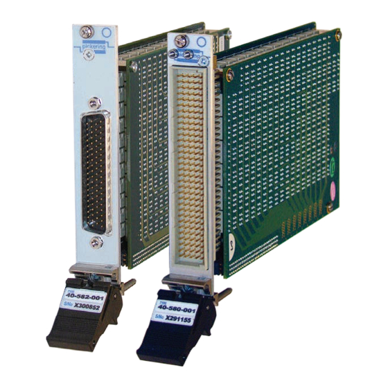
- Page 9 • Supported by PXI or LXI Chassis • Supported by BIRST ™ and eBIRST ™ Test Tools • 3 Year Warranty The 40-580/582 are 256 crosspoint PXI matrices with dual pole Supported by eBIRST switching. The matrix configurations are 16x16 or 32x8 using 2-pole electro-mechanical relays with 2A current handling.
-
Page 10: Technical Specification
Crosstalk (typical): 100kHz: -50dB directives: Low-voltage safety EN61010-1:2010, EMC Immunity 1MHz: -30dB EN61326-1:2013, Emissions EN55011:2009+A1:2010. Isolation (typical): 100kHz: 60dB 1MHz: 35dB Power Requirements +3.3V +12V -12V 400mA 1.1A 65mA pickeringtest.com 2 AMP 2-POLE HIGH DENSITY MATRIX MODULES 40-580/582/583 Page 1.2... - Page 11 This product is supported by the eBIRST test tools which simplify the identification of failed relays, the required eBIRST tools are Product Customization below. For more information go to: pickeringtest.com/ebirst Pickering PXI modules are designed and manufactured on our own Product Test Tool Adaptor Termination...
- Page 12 For more information go to: pickeringtest.com/ebirst DIN connector that is fully supported by our wide range of cable and connector accessories. Pickering’s Range of 256 Crosspoint 2 Amp PXI Matrix Modules Built-In Relay Self-Test - BIRST Matrix Size Poles Max Current Model No.
- Page 13 14MHz Crosstalk (typical): 10kHz: -70dB 100kHz: -60dB 1MHz: -40dB 10MHz -20dB Isolation (typical): 10kHz: 80dB 100kHz: 60dB 1MHz: 40dB 10MHz 25dB Power Requirements +3.3V +12V -12V 400mA 1.1A 40mA pickeringtest.com 2 AMP 2-POLE HIGH DENSITY MATRIX MODULES 40-580/582/583 Page 1.5...
- Page 14 This product is supported by the eBIRST test tools which simplify Product Customization the identification of failed relays, the required eBIRST tools are Pickering PXI modules are designed and manufactured on our own below. For more information go to: pickeringtest.com/ebirst...
- Page 15 We provide a full range of supporting cable and connector solutions for all our switching products—20 connector families with 1200+ products. We offer everything from simple mating connectors to complex cables assemblies and terminal blocks. All assemblies are manufactured by Pickering and are guaranteed to mechanically and electrically mate to our modules. Connectors & Backshells...
- Page 16 2 Pole High Density Matrix – 40-580/582 Programming Pickering provide kernel, IVI and VISA (NI & Keysight) drivers which are compatible with all Microsoft supported versions of Windows and popular older versions. For a list of all supporting operating systems, please see: pickeringtest.com/os...
-
Page 17: Technical Description
The module comprises a mother board and a daughter board populated with 2-pole electro-mechanical relays configured as a 32x8 matrix (40-580), a 16x16 matrix (40-582) or a 64x4 matrix (40-583). The relays are energised via control signals from relay drivers which are controlled from PCI bridge and control logic. The main PCI interface circuitry, drivers and relays that make up one half of the matrix are built onto the mother board. - Page 18 SECTION 2 - TECHNICAL DESCRIPTION pickering THIS PAGE INTENTIONALLY BLANK 2 AMP 2-POLE HIGH DENSITY MATRIX MODULES 40-580/582/583 Page 2.2...
-
Page 19: Installation
Modular products require installation in a suitable PXI/LXI chassis. The module is designed for indoor use only. PREOPERATION CHECKS (UNPACKING) 1. Check the module for transport damage and report any damage immediately to Pickering Interfaces. Do not attempt to install the product if any damage is evident. -
Page 20: Hardware Installation
For a system comprising more than one chassis, turn ON the last chassis in the system followed by the penultimate, etc, and finally turn ON the external controller or chassis containing the system controller. 9. For Pickering Interfaces modular LXI installation there is no requirement to use any particular power up sequence. -
Page 21: Testing Operation
Figure 3.2 - General Soft Front Panel Icon A selector panel will appear, listing all installed Pickering PCI, PXI or LXI switch cards and resistor cards. Click on the card you wish to control, and a graphical control panel is presented allowing operation of the card. - Page 22 SECTION 3 - INSTALLATION pickering THIS PAGE INTENTIONALLY BLANK 2 AMP 2-POLE HIGH DENSITY MATRIX MODULES 40-580/582/583 Page 3.4...
-
Page 23: Programming Guide
SECTION 4 - PROGRAMMING PROGRAMMING OPTIONS FOR PICKERING INTERFACES PXI MODULES For information on the installation and use of drivers and the programming of Pickering’s products in various software environments, please refer to the Software User Manual. This is available as a download from: https://www.pickeringtest.com/support/software-drivers-and-downloads... - Page 24 PROGRAMMING THE HIGH DENSITY MATRIX The 40-580, 40-582 and 40-583 are two pole switching matrices with 256 crosspoints.Connections are made by operating the relays at the crosspoints between X and Y lines allowing single X-Y connections, or X-X connections using a Y line as a path.
-
Page 25: Using Ivi Driver, Direct I/O Driver Or Visa Driver
Once the drivers are installed the manual “Sys40Prg.pdf” and driver help files which fully describes these functions can be found in the Pickering folder(s) or the Pickering entries on your Start Menu. The card must be opened before use and closed after using the following function calls: Direct I/O driver - Open with PIL_OpenCards or PIL_OpenSpecifiedCard and close with PIL_CloseCards or PIL_CloseSpecifiedCards respectively. - Page 26 SECTION 4 - PROGRAMMING GUIDE pickering THIS PAGE INTENTIONALLY BLANK 2 AMP 2-POLE HIGH DENSITY MATRIX MODULES 40-580/582/583 Page 4.4...
-
Page 27: Connector Information
Y7.2 Y8.2 ― ― 160-pin Male DIN 41612 Connector ― ― ― ― FP-GND (viewed from front of module) Figure 5.1 - 2 Amp 2-Pole 32x8 Matrix Module 40-580-001: Pinout 2 AMP 2-POLE HIGH DENSITY MATRIX MODULES 40-580/582/583 Page 5.1... - Page 28 Y13.2 Y14.2 Y15.1 Y16.1 Y15.2 Y16.2 FP_GND FP_GND Figure 5.2 - 2 Amp 2-Pole 16x16 Matrix Module 40-582-001: 78-pin D-type Front Panel Male Connector Pinout. (Viewed From Front of Module) 2 AMP 2-POLE HIGH DENSITY MATRIX MODULES 40-580/582/583 Page 5.2...
- Page 29 Y2.2 Y3.2 Y4.2 ― 160-pin Male DIN 41612 Connector ― ― ― ― FP-GND (viewed from front of module) Figure 5.3 - 2 Amp 2-Pole 64x4 Matrix Module 40-583-001: Pinout 2 AMP 2-POLE HIGH DENSITY MATRIX MODULES 40-580/582/583 Page 5.3...
- Page 30 SECTION 5 - CONNECTOR INFORMATION pickering THIS PAGE INTENTIONALLY BLANK 2 AMP 2-POLE HIGH DENSITY MATRIX MODULES 40-580/582/583 Page 5.4...
-
Page 31: Troubleshooting
PCI configuration, highlighting any potential configuration problems. Specific details of all installed Pickering switch cards are included. All the installed Pickering switch cards should be listed in the “Pilpxi information” section - if one or more cards is missing it may be possible to determine the reason by referring to the PCI configuration dump contained in the report, but interpretation of this information is far from straightforward, and the best course is to contact Pickering support: support@pickeringtest.com, if possible... - Page 32 SECTION 6 - TROUBLE SHOOTING pickering THIS PAGE INTENTIONALLY BLANK 2 AMP 2-POLE HIGH DENSITY MATRIX MODULES 40-580/582/583 Page 6.2...
-
Page 33: Relay Look-Up Tables
The Pickering Interfaces BIRST (Built-In Relay Self Test) Tool provides a simple means of testing selected Pickering Interfaces switching products, including this model. The tool can be used to find relay faults or to provide confirmation that a product is operating correctly, either as part of the regular system calibration or because a system fault is suspected and the switch system needs to be eliminated from the fault finding procedure. - Page 34 SECTION 7 - MAINTENANCE INFORMATION pickering Table 7.1 - Relay Look-Up Table: 40-580 Motherboard 40-580 RELAY CROSS REFERENCE - MOTHER BOARD Crosspoint Crosspoint Crosspoint Crosspoint Relay Relay Relay Relay 1.1, 1.2 1.1, 1.2 5.1, 5.2 1.1, 1.2 RL33 9.1, 9.2 1.1, 1.2...
- Page 35 SECTION 7 - MAINTENANCE INFORMATION pickering Table 7.2 - Relay Look-Up Table: 40-580 Daughterboard 40-580 RELAY CROSS REFERENCE - DAUGHTER BOARD Crosspoint Crosspoint Crosspoint Crosspoint Relay Relay Relay Relay 17.1, 17.2 1.1, 1.2 RL129 21.1, 21.2 1.1, 1.2 RL161 25.1, 25.2 1.1, 1.2 RL193 29.1, 29.2 1.1, 1.2...
- Page 36 RL122 RL82 RL90 RL42 RL50 RL106 RL98 RL10 RL121 RL81 RL89 RL41 RL49 RL105 RL97 Figure 7.1 - 40-580 Component Layout - Mother Board Figure 7.2 - 40-580 Component Layout - Daughter Board 2 AMP 2-POLE HIGH DENSITY MATRIX MODULES 40-580/582/583...
- Page 37 15.1 & 15.2 8.1 & 8.2 RL127 16.1 & 16.2 2.1 & 2.2 RL32 16.1 & 16.2 4.1 & 4.2 RL64 16.1 & 16.2 6.1 & 6.2 RL96 16.1 & 16.2 8.1 & 8.2 RL128 2 AMP 2-POLE HIGH DENSITY MATRIX MODULES 40-580/582/583 Page 7.5...
- Page 38 14.1 & 14.2 14.1 & 14.2 RL222 15.1 & 15.2 11.1 & 11.2 RL175 15.1 & 15.2 14.1 & 14.2 RL223 16.1 & 16.2 11.1 & 11.2 RL176 16.1 & 16.2 14.1 & 14.2 RL224 2 AMP 2-POLE HIGH DENSITY MATRIX MODULES 40-580/582/583 Page 7.6...
- Page 39 RL91 RL92 RL93 RL94 RL95 RL96 RL128 BIRST BIRST Relay Relay Spare Figure 7.3 - 40-582 Component Layout - Mother Board Figure 7.4 - 40-582 Component Layout - Daughter Board 2 AMP 2-POLE HIGH DENSITY MATRIX MODULES 40-580/582/583 Page 7.7...
- Page 40 24.1, 24.2 3.1, 3.2 RL95 32.1, 32.2 3.1, 3.2 RL127 8.1, 8.2 4.1, 4.2 RL32 16.1, 16.2 4.1, 4.2 RL64 24.1, 24.2 4.1, 4.2 RL96 32.1, 32.2 4.1, 4.2 RL128 2 AMP 2-POLE HIGH DENSITY MATRIX MODULES 40-580/582/583 Page 7.8...
- Page 41 56.1, 56.2 3.1, 3.2 RL223 64.1, 64.2 3.1, 3.2 RL255 40.1, 40.2 4.1, 4.2 RL160 48.1, 48.2 4.1, 4.2 RL192 56.1, 56.2 4.1, 4.2 RL224 64.1, 64.2 4.1, 4.2 RL256 2 AMP 2-POLE HIGH DENSITY MATRIX MODULES 40-580/582/583 Page 7.9...
- Page 42 RL122 RL118 RL98 RL78 RL126 RL86 RL110 RL90 RL70 RL121 RL117 RL97 RL77 RL125 RL85 RL109 RL89 RL69 Figure 7.5 - 40-583 Component Layout - Mother Board Figure 7.6 - 40-583 Component Layout - Daughter Board 2 AMP 2-POLE HIGH DENSITY MATRIX MODULES 40-580/582/583 Page 7.10...
Need help?
Do you have a question about the 40-580 and is the answer not in the manual?
Questions and answers