
Related Manuals for Pickering 42-724


Summary of Contents for Pickering 42-724
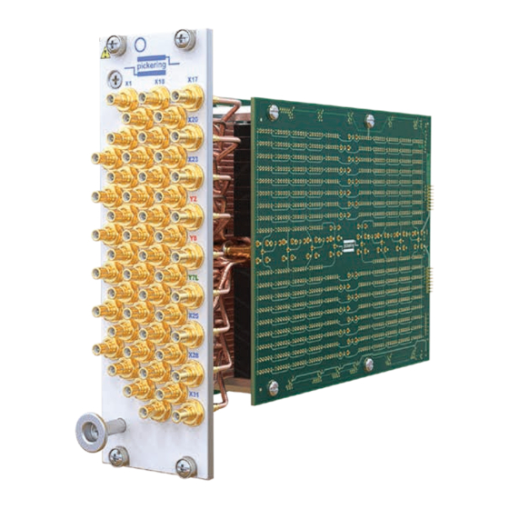
- Page 1 40/42-724 User Manual PXI/PXIe 32x8 RF Matrix Module pickeringtest.com Issue 1.2 November 2022...
- Page 2 © COPYRIGHT (2022) PICKERING INTERFACES. ALL RIGHTS RESERVED. No part of this publication may be reproduced, transmitted, transcribed, translated or stored in any form, or by any means without the written permission of Pickering Interfaces. Technical details contained within this publication are subject to change without notice.
- Page 3 Pickering Interfaces strives to fulfil all relevant environmental laws and regulations and reduce wastes and releases to the environment. Pickering Interfaces aims to design and operate products in a way that protects the environment and the health and safety of its employees, customers and the public. Pickering Interfaces endeavours to develop and manufacture products that can be produced, distributed, used and recycled, or disposed of, in a safe and environmentally friendly manner.
-
Page 4: Product Safety
If this product is heavy reference should be made to the safety instructions for provisions of lifting and moving. STATIC SENSITIVE To indicate that static sensitive devices are present and handling precautions should be followed. REED RELAY MODULE 40-110/115/120/125 32X8 RF MATRIX MODULE 40/42-724 Page (IV) Page (IV) -
Page 5: Table Of Contents
Pre Operation Checks ............3.1 Hardware Installation ............3.2 Software Installation .............3.2 Testing Operation ..............3.3 Section 4 Programming Guide ..............4.1 Programming Options For Pickering PXI/PXIe Modules ...4.1 Module Architecture ..............4.2 Programming Sub-Units ............4.3 Programming The Module ............4.4 Section 5 Connector Information ..............5.1 Section 6 Trouble Shooting .................6.1... - Page 6 THIS PAGE INTENTIONALLY BLANK 32X8 RF MATRIX MODULE 40/42-724 Page (VI)
-
Page 7: Warnings And Cautions
Unused slots in the host chassis are populated with blanking plates to prevent access to user I/O signals that may be present. Blanking panels are available to order from Pickering in a variety of slot widths. If the product is not used in this manner for example by using an extender card then additional care must be taken to avoid contact with exposed signals. - Page 8 THIS PAGE INTENTIONALLY BLANK 32X8 RF MATRIX MODULE 40/42-724 Page (VIII)
-
Page 9: Technical Specification
RF performance. Matrix Operation The 40/42-724 is a high density matrix designed to provide a Y to X connection to maximize bandwidth. This module is based on the same construction as the popular 40-725 RF matrix, but has increased capacity and optional Y axis loop thru allowing easy expansion. - Page 10 32x8 RF Coaxial Matrix, 40/42-724 Y Axis Loop-Thru The easy to use loop-thru option allows 40/42-724 modules to be cascaded to form larger matrices whilst minimizing impact on RF performance. The 40/42-724-021-L version of the module has Y loop-thru connectors on the front panel which are simply plugged into the Y connectors of the adjacent matrix module via SMB to SMB coaxial cables.
- Page 11 SECTION 1 - TECHNICAL SPECIFICATION pickering Overview 32x8 RF Coaxial Matrix, 40/42-724 40/42-724-021 Module #3 40/42-724-021-L Module #2 Y Loop-Thru Coaxial Cables 40/42-724-021-L Module #1 Y Loop-Thru Coaxial Cables Y1 Y2 Y3 Y4 Y5 Y6 Y7 Y8 Y Connections 2 off 40-724-021-L and 1 off 40-724-021 32x8 RF Matrix Modules Interconnected as a 96x8 Matrix pickeringtest.com...
- Page 12 Specifications 32x8 RF Coaxial Matrix, 40/42-724 RF Performance Plots for 40/42-724 RF Matrix Module 40/42-724-0xx Insertion Loss For X to Y Signal Paths 40/42-724-0xx-L Insertion Loss For X to Y Signal Paths 40/42-724-0xx VSWR For X to Y Signal Paths 40/42-724-0xx-L VSWR For X to Y Signal Paths pickeringtest.com...
- Page 13 0.5 A Maximum Switch Power: 10 W 40-724 - Dual slot 3U PXI (CompactPCI card). Characteristic Impedance: 50 Ω 42-724 - Dual slot 3U PXIe, compatible with PXIe hybrid On Path Resistance: <1000 mΩ slot. Off Path Resistance: >10 Ω...
- Page 14 Switching System Test Tool PXI 32x8 RF Coaxial Matrix: SMB, 50Ω 40-724-021 40/42-724 is supported by the eBIRST test tools which SMB, 50Ω with loop-thru on Y axis 40-724-021-L simplify the identification of failed relays, the required eBIRST tools are below. For more information go to: PXI 32x4 RF Coaxial Matrix: pickeringtest.com/ebirst...
- Page 15 We provide a full range of supporting cable and connector solutions for all our switching products—20 connector families with 1200+ products. We offer everything from simple mating connectors to complex cables assemblies and terminal blocks. All assemblies are manufactured by Pickering and are guaranteed to mechanically and electrically mate to our modules. Connectors & Backshells...
- Page 16 32x8 RF Coaxial Matrix, 40/42-724 Programming Pickering provide kernel, IVI and VISA (NI & Keysight) drivers which are compatible with all Microsoft supported versions of Windows and popular older versions. For a list of all supporting operating systems, please see: pickeringtest.com/os...
- Page 17 PERFORMANCE GRADIENT The bandwidth performance of the 40/42-724 family varies greatly dependent on the selected signal path. The following images define, in terms of frequency, the -3db insertion loss point for all paths within the 40/42-724-021 and 40/42-724-021 modules. 3dB Bandwidth Figure 1.1 - 40/42-724-021 Bandwidth Variation with Signal Path...
- Page 18 SECTION 1 - TECHNICAL SPECIFICATION pickering 3dB Bandwidth Figure 1.2 - 40/42-724-021-L Bandwidth Variation with Signal Path 32X8 RF MATRIX MODULE 40/42-724 Page 1.10...
-
Page 19: Technical Description
FUNCTIONAL DESCRIPTION A functional block diagram for the 40/42-724 is provided in Figure 2.1. The RF matrix Module is powered by 3.3V and 5V inputs via Compact PCI connector J1, or 3.3V and 12V inputs via PXIe connector XJ3 and XJ4. The interface to the user test equipment is via front panel mounted coaxial connectors. - Page 20 RL34 RL35 RL36 RL37 RL38 RL39 RL40 Figure 2.2 - 40/42-724-021 32x8 RF Matrix Module: Switching Diagram Showing Default Switch Positions *Connections YLT1-8 are only fitted to the 40/42-724-021-L which includes Y loop-thru 32X8 RF MATRIX MODULE 40/42-724 Page 2.2...
- Page 21 RL154 RL155 RL156 RL157 RL158 RL159 RL160 Figure 2.3 - 40/42-724-022 32x4 RF Matrix Module: Switching Diagram Showing Default Switch Positions *Connections YLT1-4 are only fitted to the 40/42-724-022-L which includes Y loop-thru 32X8 RF MATRIX MODULE 40/42-724 Page 2.3...
- Page 22 RL36 RL35 RL34 RL33 Figure 2.4 - 40/42-724-011 16x8 RF Matrix Module: Switching Diagram Showing Default Switch Positions *Connections YLT1-8 are only fitted to the 40/42-724-011-L which includes Y loop-thru 16x4 RF Matrix Daughter Board RL176 RL172 YLT1* RL128 RL127...
-
Page 23: Installation
Modular products require installation in a suitable PXI/PXIe/LXI chassis. The module is for indoor use only. PREOPERATION CHECKS (UNPACKING) 1. Check the module for transport damage and report any damage immediately to Pickering Interfaces. Do not attempt to install the product if any damage is evident. -
Page 24: Hardware Installation
For a system comprising more than one chassis, turn ON the last chassis in the system followed by the penultimate, etc, and finally turn ON the external controller or chassis containing the system controller. 9. For Pickering Interfaces modular LXI installation there is no requirement to use any particular power up sequence. -
Page 25: Testing Operation
Figure 3.2 - General Soft Front Panel Icon A selector panel will appear, listing all installed Pickering PCI, PXI or LXI switch cards and resistor cards. Click on the card you wish to control, and a graphical control panel is presented allowing operation of the card. - Page 26 SECTION 3 - INSTALLATION pickering THIS PAGE INTENTIONALLY BLANK 32X8 RF MATRIX MODULE 40/42-724 Page 3.4...
-
Page 27: Programming Guide
SECTION 4 - PROGRAMMING GUIDE PROGRAMMING OPTIONS FOR PICKERING INTERFACES PXI/PXIe MODULES For information on the installation and use of drivers and the programming of Pickering’s products in various software environments, please refer to the Software User Manual. This is available as a download from: https://www.pickeringtest.com/support/software-drivers-and-downloads... -
Page 28: Module Architecture
MODULE ARCHITECTURE The 40/42-724-021 is a 32x8 matrix with isolation relays on the X and Y axis. It is constructed from two 16x8 daughter cards and in the default state all relays are open circuit. Energising a particular crosspoint relay creates a signal path between the corresponding X and Y terminals. -
Page 29: Programming The Module
Once the drivers are installed the manual “Sys40Prg.pdf” and driver help files which fully describes these functions can be found in the Pickering folder(s) or the Pickering entries on your Start Menu. The card must be opened before use and closed after using the following function calls: Direct I/O Driver - Open with PIL_OpenCards or PIL_OpenSpecifiedCard and close with PIL_CloseCards or PIL_CloseSpecifiedCards respectively. - Page 30 SECTION 4 - PROGRAMMING GUIDE pickering Programming the 40/42-724 module with the IVI driver: A specific string for the module is defined in the IVI configuration, as shown in the tables below: 40/42-724-021 40/42-724-011 40/42-724-022 40/42-724-012 Model Model Model Model...
- Page 31 IVI channel names are shown in For example, to connect Y1 to X1 on a 40-724-021-L: Connect(“X1”, “Y1”) The isolation relays will automatically be set to the correct position. 32X8 RF MATRIX MODULE 40/42-724 Page 4.5...
- Page 32 SECTION 4 - PROGRAMMING GUIDE pickering THIS PAGE INTENTIONALLY BLANK 32X8 RF MATRIX MODULE 40/42-724 Page 4.6...
-
Page 33: Connector Information
SECTION 5 - CONNECTOR INFORMATION pickering pickering Figure 5.1 - RF Matrix Module Figure 5.2 - RF Matrix Module 40/42-724-021: Pin-Outs 40/42-724-021-L: Pin-Outs (32x8 RF Matrix without Loop-thru) (32x8 RF Matrix with Y Loop-thru) 32X8 RF MATRIX MODULE 40/42-724 Page 5.1... - Page 34 SECTION 5 - CONNECTOR INFORMATION pickering pickering pickering Figure 5.3 - RF Matrix Module Figure 5.4 - RF Matrix Module 40/42-724-011: Pin-Outs 40/42-724-011-L: Pin-Outs (16x8 RF Matrix without Loop-thru) (16x8 RF Matrix with Y Loop-thru) 32X8 RF MATRIX MODULE 40/42-724 Page 5.2...
-
Page 35: Trouble Shooting
SECTION 6 - TROUBLE SHOOTING pickering pickering pickering Figure 5.5 - RF Matrix Module Figure 5.6 - RF Matrix Module 40/42-724-022: Pin-Outs 40/42-724-022-L: Pin-Outs (32x4 RF Matrix without Loop-thru) (32x4 RF Matrix with Y Loop-thru) 32X8 RF MATRIX MODULE 40/42-724 Page 6.3... - Page 36 SECTION 6 - TROUBLE SHOOTING pickering pickering pickering Figure 5.7 - RF Matrix Module Figure 5.8 - RF Matrix Module 40/42-724-012: Pin-Outs 40/42-724-012-L: Pin-Outs (16x4 RF Matrix without Loop-thru) (16x4 RF Matrix with Y Loop-thru) 32X8 RF MATRIX MODULE 40/42-724 Page 6.4...
-
Page 37: Maintenance Information
PCI configuration, highlighting any potential configuration problems. Specific details of all installed Pickering switch cards are included. All the installed Pickering switch cards should be listed in the “Pilpxi information” section - if one or more cards is missing it may be possible to determine the reason by referring to the PCI configuration dump contained in the report, but interpretation of this information is far from straightforward, and the best course is to contact Pickering support: support@pickeringtest.com, if possible... - Page 38 SECTION 6 - TROUBLE SHOOTING pickering THIS PAGE INTENTIONALLY BLANK 32X8 RF MATRIX MODULE 40/42-724 Page 6.2...
-
Page 39: Relay Lookup Tables
For PXI modules which are supported in one of Pickering Interfaces’ Modular LXI Chassis (such as the 60-102B and 60-103B) no module software update is required. If the module was introduced after the LXI chassis was manufactured the module may not be recognized, in this case the chassis firmware may need upgrading. - Page 40 SECTION 7 - MAINTENANCE INFORMATION pickering Table 7.1 - RF Matrix Module 40/42-724: 16x8 Daughter Board 1 Relay Numbering (relay numbers in red are not fitted to the partially populated 16x4 daughter board) 16x8 RF Matrix Daughter Board 1 (Signal paths with relay energised)
- Page 41 SECTION 7 - MAINTENANCE INFORMATION pickering Table 7.2 - RF Matrix Module 40/42-724: 16x8 Daughter Board 2 Relay Numbering (relay numbers in red are not fitted to the partially populated 16x4 daughter board) 16x8 RF Matrix Daughter Board 2 (Signal paths with relay energised)
- Page 42 RL104 RL112 RL120 RL128 X Isolation Relays Figure 7.1 - RF Matrix Module 40/42-724: 16x8 Daughter Board Component Layout (relay numbers in red are not fitted to the partially populated 16x4 daughter board) 32X8 RF MATRIX MODULE 40/42-724 Page 7.4...
Need help?
Do you have a question about the 42-724 and is the answer not in the manual?
Questions and answers