
Related Manuals for Pickering 40-280


Summary of Contents for Pickering 40-280
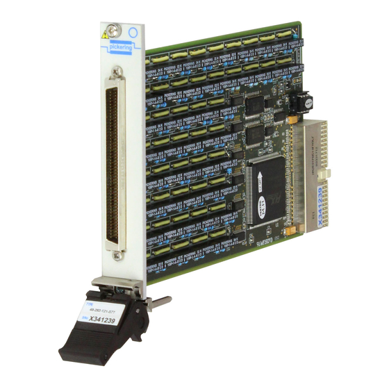
- Page 1 40-280/281/282 User Manual PXI Selectable Resistor Module pickeringtest.com Issue 3.3 January 2020...
- Page 2 © COPYRIGHT (2020) PICKERING INTERFACES. ALL RIGHTS RESERVED. No part of this publication may be reproduced, transmitted, transcribed, translated or stored in any form, or by any means without the written permission of Pickering Interfaces. Technical details contained within this publication are subject to change without notice.
- Page 3 Pickering Interfaces strives to fulfil all relevant environmental laws and regulations and reduce wastes and releases to the environment. Pickering Interfaces aims to design and operate products in a way that protects the environment and the health and safety of its employees, customers and the public. Pickering Interfaces endeavours to develop and manufacture products that can be produced, distributed, used and recycled, or disposed of, in a safe and environmentally friendly manner.
-
Page 4: Product Safety
If this product is heavy reference should be made to the safety instructions for provisions of lifting and moving. STATIC SENSITIVE To indicate that static sensitive devices are present and handling precautions should be followed. REED RELAY MODULE 40-110/115/120/125 SELECTABLE RESISTOR MODULE 40-280/281/282 Page (IV) Page (IV) -
Page 5: Table Of Contents
Pre Operation Checks ............3.1 Hardware Installation ............3.2 Software Installation .............3.2 Testing Operation ..............3.3 Section 4 Programming Guide ..............4.1 Programming Options For Pickering PXI Modules ....4.1 Module Architecture 40-280 ..........4.2 Module Architecture 40-281 ..........4.3 Module Architecture 40-282 ..........4.4 Programming The Module ............4.5 Section 5 Connector Information ..............5.1... - Page 6 THIS PAGE INTENTIONALLY BLANK SELECTABLE RESISTOR MODULE 40-280/281/282 Page (VI)
-
Page 7: Warnings And Cautions
Not to be used in safety critical circuits, refer to the Pickering Interfaces’ terms & conditions of sale. This module must not be used for the switching of Mains Circuits. For the switching of voltages up to the module’s full specification, Secondary Circuit power supplies and the Device Under Test must... - Page 8 • For suitably equipped products in the event of an emergency press the red “emergency stop” button situated on the front of the unit. SELECTABLE RESISTOR MODULE 40-280/281/282 Page (VIII) 2 AMP 1-POLE UHD MATRIX MODULES 40-575 / 576 / 577 / 578 / 579...
-
Page 9: Technical Specification
Modules are supplied without any resistors fitted, permitting the The 40-280 provides up to 48 isolated channels, each of which can user to fit the values required. The flexibility of this allows users be programmed as a short circuit, an open circuit or a fixed resistor to select components that best meet their application needs. - Page 10 Safety & CE Compliance +3.3V +12V -12V All modules are fully CE compliant and meet applicable EU 0.57A max directives: Low-voltage safety EN61010-1:2010, EMC Immunity EN61326-1:2013, Emissions EN55011:2009+A1:2010. PCB Layout for the 40-280 Selectable Resistor Module pickeringtest.com SELECTABLE RESISTOR MODULE 40-280/281/282 Page 1.2...
- Page 11 40-282-121 Resistance Resolution Note: Modules are supplied without any resistors fitted. Please Overall Accuracy contact the Pickering Sales Office if you require the module to be Maximum Power/Current pre-fitted with resistors. Number of Channels (variable resistors) Mating Connectors & Cabling †...
- Page 12 We provide a full range of supporting cable and connector solutions for all our switching products—20 connector families with 1200+ products. We offer everything from simple mating connectors to complex cables assemblies and terminal blocks. All assemblies are manufactured by Pickering and are guaranteed to mechanically and electrically mate to our modules. Connectors & Backshells...
- Page 13 Selectable Resistor – 40-280/281/282 Programming Pickering provide kernel, IVI and VISA (NI & Keysight) drivers which are compatible with all Microsoft supported versions of Windows and popular older versions. For a list of all supporting operating systems, please see: pickeringtest.com/os The VISA driver is also compatible with Real-Time Operating Systems such as LabVIEW RT.
- Page 14 SECTION 1 - TECHNICAL SPECIFICATION pickering THIS PAGE INTENTIONALLY BLANK SELECTABLE RESISTOR MODULE 40-280/281/282 Page 1.6...
-
Page 15: Technical Description
The relay driver is addressed by PCI bridge U1 to output the required signal. Module configuration is determined by hardwired links and data stored in EEPROM U7. PCI Bridge U1 is configured by EEPROM U2. SELECTABLE RESISTOR MODULE 40-280/281/282 Page 2.1... - Page 16 • 40-280-021- 24 Channel • 40-282-021- 12 Channel • 40-281-021- 12 Channel • 40-282-121- 24 Channel • 40-280-121- 48 Channel • 40-281-121- 24 Channel Figure 2.1 - Selectable Resistor Module (40-280/281/282): Functional Block Diagram SELECTABLE RESISTOR MODULE 40-280/281/282 Page 2.2...
-
Page 17: Installation
Modular products require installation in a suitable PXI/LXI chassis. The module is designed for indoor use only. PREOPERATION CHECKS (UNPACKING) 1. Check the module for transport damage and report any damage immediately to Pickering Interfaces. Do not attempt to install the product if any damage is evident. -
Page 18: Hardware Installation
For a system comprising more than one chassis, turn ON the last chassis in the system followed by the penultimate, etc, and finally turn ON the external controller or chassis containing the system controller. 9. For Pickering Interfaces modular LXI installation there is no requirement to use any particular power up sequence. -
Page 19: Testing Operation
Figure 3.2 - General Soft Front Panel Icon A selector panel will appear, listing all installed Pickering PCI, PXI or LXI switch cards and resistor cards. Click on the card you wish to control, and a graphical control panel is presented allowing operation of the card. - Page 20 SECTION 3 - INSTALLATION pickering THIS PAGE INTENTIONALLY BLANK SELECTABLE RESISTOR MODULE 40-280/281/282 Page 3.4...
-
Page 21: Programming Guide
SECTION 4 - PROGRAMMING GUIDE PROGRAMMING OPTIONS FOR PICKERING INTERFACES PXI MODULES For information on the installation and use of drivers and the programming of Pickering’s products in various software environments, please refer to the Software User Manual. This is available as a download from: https://www.pickeringtest.com/support/software-drivers-and-downloads... -
Page 22: Module Architecture 40-280
MODULE ARCHITECTURE 40-280-021/121 The 40-280-021 is an array of 48, and the 40-280-121 is an array of 96 SPST relays. In the default state, all signal paths are open circuit. Energising a particular relay creates a signal path between the C and A terminals. The relay module’s channel architecture is shown in its default state in the diagram below. -
Page 23: Module Architecture 40-281
Further information can be found in Figure 2.1. Roffset Vout Vref 40-280 Single Resistor Card 40-281 Dual Resistor Card 40-282 Potential Divider 40-281-021/121 One sub-unit of 24 bits (40-281-021) or 48 bits (40-281-121) is used to control all the module’s relays as shown below. -
Page 24: Module Architecture 40-282
Signal Path Sub-Unit Sub-Unit (with relay energised) (with relay energised) C1 to A1 C1 to A1 C2 to A2 C2 to A2 C47 to A47 C23 to A23 C48 to A48 C24 to A24 SELECTABLE RESISTOR MODULE 40-280/281/282 Page 4.4... -
Page 25: Programming The Module
// Operates the A1/C1 relay pi40iv_Disconnect(vi, com1, ch1); // Releases the A1/C1 relay pi40iv_Connect(vi, com6, ch6); // Operates the A6/C6 relay The IVI Swtch driver specification contains no bulk setting capabilities. SELECTABLE RESISTOR MODULE 40-280/281/282 Page 4.5... - Page 26 SECTION 4 - PROGRAMMING GUIDE pickering THIS PAGE INTENTIONALLY BLANK SELECTABLE RESISTOR MODULE 40-280/281/282 Page 4.6...
-
Page 27: Connector Information
CH23 IN CH23 OUT CH47 OUT CH23 OUT CH24 IN CH48 IN CH24 IN CH24 OUT CH48 OUT CH24 OUT 40-280-021 40-280-121 Figure 5.1 - Pinouts: 40-280-021/121 (96-pin Micro-D Connector Viewed From Front of Module) SELECTABLE RESISTOR MODULE 40-280/281/282 Page 5.1... - Page 28 CH18 OUT CH6 OUT CH7 IN CH19 IN CH7 IN Vref CH7 OUT CH19 OUT CH7 OUT 40-280 Single Resistor Card 40-281 Dual Resistor Card 40-282 Potentia CH8 IN CH20 IN CH8 IN CH8 OUT CH20 OUT CH8 OUT CH9 IN...
- Page 29 CH19 IN CH7 IN CH7 OUT CH19 OUT CH7 OUT Vref V7 REF V19 REF V7 REF 40-280 Single Resistor Card 40-281 Dual Resistor Card 40-282 Potential Divider CH8 IN CH20 IN CH8 IN CH8 OUT CH20 OUT CH8 OUT...
- Page 30 SECTION 5 - CONNECTOR INFORMATION pickering THIS PAGE INTENTIONALLY BLANK SELECTABLE RESISTOR MODULE 40-280/281/282 Page 5.4...
-
Page 31: Trouble Shooting
PCI configuration, highlighting any potential configuration problems. Specific details of all installed Pickering switch cards are included. All the installed Pickering switch cards should be listed in the “Pilpxi information” section - if one or more cards is missing it may be possible to determine the reason by referring to the PCI configuration dump contained in the report, but interpretation of this information is far from straightforward, and the best course is to contact Pickering support: support@pickeringtest.com, if possible... - Page 32 SECTION 6 - TROUBLE SHOOTING pickering THIS PAGE INTENTIONALLY BLANK SELECTABLE RESISTOR MODULE 40-280/281/282 Page 6.2...
-
Page 33: Maintenance Information
Refer to the Warnings and Cautions at the front of this manual RESISTOR INFORMATION The 40-280, 40-281 and 40-282 Resistor Modules are designed so that the user can fit their own resistors values to suit the required application. The maximum recommended dimensions for the resistors suitable for fitting to the module are shown in Figure 7.1 below:... - Page 34 SECTION 7 - MAINTENANCE INFORMATION pickering TABLE 7.1 - 24 Channel Selectable Resistor Module 40-280-021: Relay Numbering Signal Path Signal Path Signal Path Signal Path 40-280-021 40-280-021 40-280-021 40-280-021 (relay) (relay) (relay) (relay) Relay No. Relay No. Relay No. Relay No.
- Page 35 SECTION 7 - MAINTENANCE INFORMATION pickering TABLE 7.2 - 48 Channel Selectable Resistor Module 40-280-121: Relay Numbering Signal Path Signal Path Signal Path Signal Path 40-280-121 40-280-121 40-280-121 40-280-121 (relay) (relay) (relay) (relay) Relay No. Relay No. Relay No. Relay No.
- Page 36 Note: All signal paths include the Offset resistance. RL18 RL34 RL19 RL35 RL22 RL38 RL23 RL39 RL10 RL26 RL42 RL11 RL27 RL43 RL14 RL30 RL46 RL15 RL31 RL47 Figure 7.4 - 12 Channel Selectable Resistor Module 40-281-021: Component Layout SELECTABLE RESISTOR MODULE 40-280/281/282 Page 7.4...
- Page 37 RL39 RL55 RL71 RL10 RL26 RL42 RL58 RL74 RL11 RL27 RL43 RL59 RL75 RL14 RL30 RL46 RL62 RL78 RL15 RL31 RL47 RL63 RL79 Figure 7.5 - 24 Channel Selectable Resistor Module 40-281-121: Component Layout SELECTABLE RESISTOR MODULE 40-280/281/282 Page 7.5...
- Page 38 Ch12 R24short RL48 RL18 RL34 RL20 RL36 RL22 RL38 RL24 RL40 RL10 RL26 RL42 RL12 RL28 RL44 RL14 RL30 RL46 RL16 RL32 RL48 Figure 7.6 - 12 Channel Selectable Resistor Module 40-282-021: Component Layout SELECTABLE RESISTOR MODULE 40-280/281/282 Page 7.6...
- Page 39 RL40 RL56 RL72 RL10 RL26 RL42 RL58 RL74 RL12 RL28 RL44 RL60 RL76 RL14 RL30 RL46 RL62 RL78 RL16 RL32 RL48 RL64 RL80 Figure 7.7 - 24 Channel Selectable Resistor Module 40-282-121: Component Layout SELECTABLE RESISTOR MODULE 40-280/281/282 Page 7.7...
- Page 40 SECTION 7 - MAINTENANCE INFORMATION pickering Figure 7.8 - 48 Channel Selectable Resistor Module 40-280-121 SELECTABLE RESISTOR MODULE 40-280/281/282 Page 7.8...
Need help?
Do you have a question about the 40-280 and is the answer not in the manual?
Questions and answers