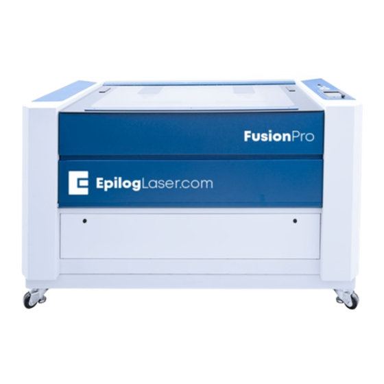
Epilog Laser Fusion Pro 32 Manual
Hide thumbs
Also See for Fusion Pro 32:
- Assembly replacement (22 pages) ,
- Manual (8 pages) ,
- Original instructions manual (242 pages)
Advertisement
Quick Links
Parts Required
•
CS0400 - Assy, X-Axis Rail, 32x20
•
Fusion Pro 32
•
CS1200 - Assy, X-Axis Rail, 48x36
•
Fusion Pro 48
X-Axis Assembly Replacement
Fusion Pro 32 & 48
Tools/Materials Required
•
5/32" Allen Wrench
•
5/16" Nut Driver
•
Phillips Head Screwdriver
www.epiloglaser.com
tech@epiloglaser.com
303-215-9171
07/2023
.
Advertisement

Summary of Contents for Epilog Laser Fusion Pro 32
- Page 1 303-215-9171 X-Axis Assembly Replacement Fusion Pro 32 & 48 Parts Required Tools/Materials Required • CS0400 - Assy, X-Axis Rail, 32x20 • 5/32” Allen Wrench • Fusion Pro 32 • 5/16” Nut Driver • CS1200 - Assy, X-Axis Rail, 48x36 •...
- Page 2 16000 - X-Axis Replacement X-Axis Assembly 4. Manually move the x-axis assembly to the middle of the engraver: Replacement X-Axis Assembly Removal 1. Turn off the engraver. 2. Disconnect engraver from power source. 3. Remove the left and right panels of the engraver by loosening the 5/32”...
- Page 3 16000 - X-Axis Replacement 7. Remove the left and right bellows 11. Disconnect the air tubing from the by loosening the six (6) 5/16” nuts and elbow connector at right side of the backing plate: x-axis assembly: 8. Loosen, but do not remove the four (4) Phillips screws that hold the x-axis The air tubing is held by a retaining fix- ture.
- Page 4 16000 - X-Axis Replacement 13. Remove the x-axis drive board 15. Lift the x-axis assembly upwards to housing: clear the locator pins on the left and right y-axis bearing blocks: 14. Remove and or loosen the four (4) 5/32” fasteners that secure the x-axis assembly to the y-axis bearings.
- Page 5 16000 - X-Axis Replacement X-Axis Assembly Installation 3. Install and/or tighten the four (4) 5/32” fasteners that secure the x-axis assembly to the y-axis bearings. There 1. Slide the x-axis assembly into the are two (2) on the right side and two (2) engraver through the right side of the on the left side: machine:...
- Page 6 16000 - X-Axis Replacement 5. Install and tighten the four (4) 7/64” 7. Reconnect the seven (7) electrical hex screws that hold the x-axis drive connectors from the drive board: board housing: The electrical connectors on the drive board are all unique and will only fit into 6.
- Page 7 16000 - X-Axis Replacement Updates and Programming 10. Position the lens tube in the lens assembly, ensuring that the notch in the tube faces the rear of the The x-axis assembly contains many engraver. Make sure to hold the lens components, including circuit boards, tube after inserting to ensure that it cameras, and a motor.
- Page 8 16000 - X-Axis Replacement 3. Enter the Diagnostics menu and 5. Allow the engraver to complete scroll to the Camera tab. Press Test & the update. Once done, a success Update: message will appear: 4. Press Update: Updating the Peripherals 1.
- Page 9 After replacing the x-axis assembly, complete a full focus calibration and laser alignment. If further assistance is required, contact Epilog Laser Technical Support by phone at 303-215-9171, or by email at tech@epiloglaser.com. 3. Once in the Peripheral Update menu, select Motor Drives and FPGA. Press...


Need help?
Do you have a question about the Fusion Pro 32 and is the answer not in the manual?
Questions and answers