
Subscribe to Our Youtube Channel
Related Manuals for Mountup MU2005


Summary of Contents for Mountup MU2005
- Page 1 Monitor Wall Mount Instruction Manual 75x75mm 100x100mm 200x100mm 100x200mm 2~12kg 200x200mm 4.4~26.5lbs If you have any questions , please contact our customer service. 80002-MA02-112WA-US1.0...
-
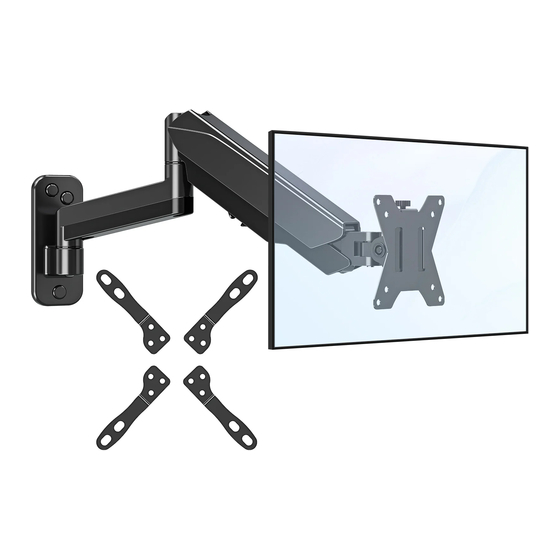
Page 2: Package Contents
WARNING! If you have any confusions or are not quite sure about the installation, please do not hesitate to ask for our help. Before assembly, please check and make sure all necessary accessories are included and undamaged. Improper installation, such as use the product for monitors over its load capacity or for any purpose not explicitly speci ed, may cause damage or serious injury. -
Page 3: Assembly Steps
ASSEMBLY STEPS WARNING DO NOT install into drywall alone. STEP 1: Attach Arm Assembly to Wall OPTION A: Wood Stud Installation Min. 102mm (4") Min. 51mm (2") <16mm (5/8") Position the Arm Assembly (A) at your desired height and line up the holes with your stud center line. - Page 4 STEP 1: (Continued) OPTION B: Solid Concrete Wall Installation Min. 8"(203mm) Position the Arm Assembly (A) at your desired height , level the Arm Assembly (A) and mark the pilot hole locations. 60mm (2.4") ø10mm (ø 3/8") Drill pilot holes using a ø3/8". (ø10 mm) diameter drill bit.
- Page 5 STEP 2: Attach Decorative Cover Attach Decorative Covers (D) to Lag Bolts (W-A).
-
Page 6: Con Guration
STEP 3: VESA Configures for VESA hole pattern: VESA pattern Con guration 75x75mm, 100x100mm (WxH) 100mm 75mm x 75mm 75mm 100mm x 100mm 200mm x 100mm 100mm x 200mm 200mm x 200mm for VESA hole pattern: 200x100mm 200mm for VESA hole pattern: 100x200mm 100mm for VESA hole pattern: 200x200mm 200mm... - Page 7 STEP 4 : Attach Monitor OPTION A: Flat Back Monitor Attach the VESA plate (B) to back of monitor and secure Monitor Monitor Monitor it by using a 6mm Allen Key(E) to tighten screws(M-A) Do not tighten the screws excessively or your monitor might be damaged.
- Page 8 STEP 5: Hang Monitor Slide the monitor onto the head of swivel arm, install the security bolt (C). Make sure the security bolt is installed before you rotate the monitor. Important Notice: The gas spring is pre-set to minimum tension. Once the monitor is hanged on, hold the monitor with both hands and DO NOT let go suddenly or immediately.
- Page 9 STEP 6: Adjust Tension For intended functioning of the mount, you may need to adjust the tension of Upper Arm (A) in accordance with your monitor weight by 6 mm Allen Key (E). CAUTION Note1: Be sure to keep the arm in horizontal position during adjustment. Situation 1: Arm falls down Upper Arm with monitor falls down and fails to stay where intended.
-
Page 10: Step 7: Cable Management
STEP 7: Cable Management STEP 5: (Continued) Remove bottom plastic covers from gas spring arm as shown in diagram. Run cables from monitor through bottom of gas spring arm. Reattach plastic covers as shown in diagram. - Page 11 Adjust as Desired Adjust monitor position and rotation. Tilt Swivel Rotation Height Swivel 180° +90° Tilt Rotation Swivel -45° 360° ±135° Swivel Height 180° Note: To ensure stability, the tightness of the rotating axis has been preset, so it would be kind of di cult to rotate the VESA plate. Suggestion: Please attach the monitor rst, then hold the two sides of it with both hands, and rotate vigorously.
-
Page 12: Product Dimensions
Product Dimensions ±90° ±135° 53mm /2.1" 210mm-262mm 8.2"-10.3" ±90° 360° VESA 200mm/100mm/75mm CAUTION AND MAINTENANCE: • Never allow children to climb, stand, hang, or play on any part of monitor or stand. • This product is intended for indoor use only. Using this product outdoors could lead to product failure and personal injury.
Need help?
Do you have a question about the MU2005 and is the answer not in the manual?
Questions and answers