Table of Contents
Advertisement
Quick Links
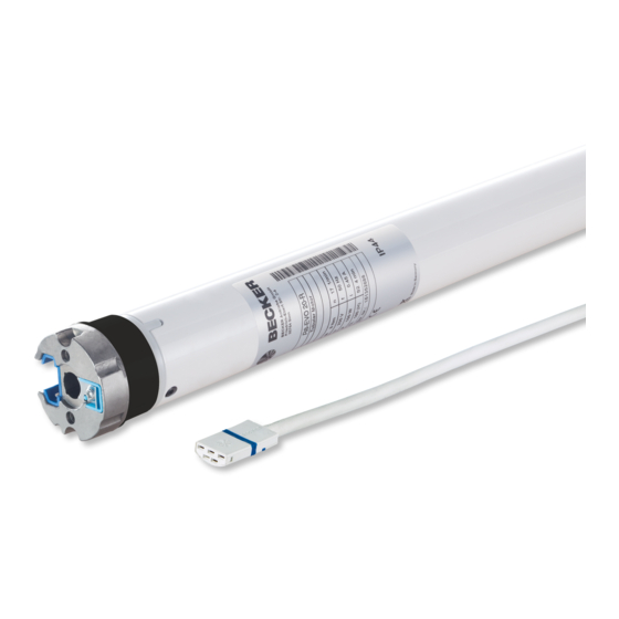
R8-17...R20-17
Model: EVO 20 R, EVO 20 R BT
Assembly and Operating Instructions
en
Tubular drive with variable output speeds for roller
shutter systems and vertical fabric shades.
Important information for:
• Fitters / • Electricians / • Users
Please forward accordingly!
These instructions must be kept safe for future reference.
1010 300 002 0j 10/11/2022
Becker-Antriebe GmbH
Friedrich-Ebert-Straße 2-4
35764 Sinn/Germany
www.becker-antriebe.com
Advertisement
Table of Contents


Need help?
Do you have a question about the R8-17-EVO 20 R and is the answer not in the manual?
Questions and answers