Advertisement
Quick Links
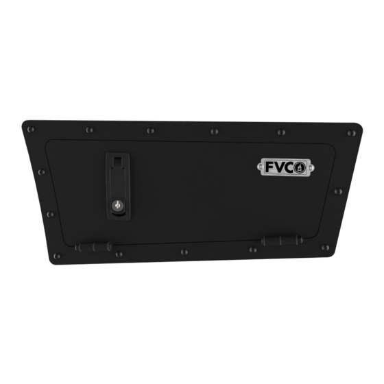
S PRI NTER PANE L STOR AGE LOCKE R
SP1123 B + SP1 124B
INSTALLATION
GUIDE
F L AT L I N E VA N C O • S U P P O R T @ F L AT L I N EVA N C O . C O M • 8 8 8 - 6 6 7- 5 5 7 6
TOOLS REQUIRED
(NOT INCLUDED)
+
PAINT
+
TAPE MEASURE
+
10MM Wrench
+
MARKER
+
8MM Wrench
+
POWER DRILL
+
3MM Allen Wrench
+
7/32" DRILL BIT
+
2.5MM Allen Wrench
+
CENTER PUNCH
+
DIE GRINDER (optional)
+
HAMMER
+
ANGLE GRINDER or BODY SAW
+
STEP BIT
+
METAL CUTOFF WHEEL or BLADE
+
METAL FILE
+
MASKING TAPE
INSTALL INFO
TIME TO INSTALL THIS PRODUCT: 2 HOURS
Additional help is suggested for a few of the install
steps.
BEFORE YOU START
Please inspect the product and packaging upon
delivery to ensure there are no issues and that all
parts and hardware are accounted for.
Contact us ASAP if anything is missing at:
support@flatlinevanco.com
0 1
Advertisement

Related Manuals for FVC SPRINTER SP1123B


Summary of Contents for FVC SPRINTER SP1123B
- Page 1 INSTALLATION GUIDE S PRI NTER PANE L STOR AGE LOCKE R SP1123 B + SP1 124B TOOLS REQUIRED (NOT INCLUDED) PAINT TAPE MEASURE 10MM Wrench MARKER 8MM Wrench POWER DRILL 3MM Allen Wrench 7/32” DRILL BIT 2.5MM Allen Wrench CENTER PUNCH DIE GRINDER (optional) HAMMER ANGLE GRINDER or BODY SAW...
-
Page 2: Before You Start
BEFORE YOU START All Flatline Van Co products must be properly assembled and secured before attaching to your vehicle. Improper attachment could result in an automobile accident, and could cause serious bodily injury or death to you or to others involved. You are responsible for assembling and securing Flatline Van Co products to your vehicle, checking the mounting points and attachments prior to use, and regularly inspecting the products for wear and or damage. -
Page 3: Package Contents
PACKAGE CONTENTS DRIVER SIDE DOOR FRAME ASSEMBLY BACKING PLATE 1 BACKING PLATE 2 DRILL/CUT TEMPLATE DOOR FRAME GASKET QTY: 1 QTY: 1 QTY: 1 QTY: 1 QTY: 1 PASSENGER SIDE DOOR FRAME ASSEMBLY BACKING PLATE 1 BACKING PLATE 2 DRILL/CUT TEMPLATE DOOR FRAME GASKET QTY: 1 QTY: 1... - Page 4 HARDWARE M5 SCREW X 15 O.D. FLAT M5-0.8 X 20 BUTTON HEAD M5-0.8 X 12 BUTTON HEAD M5-0.8 NYLON LOCKNUT WASHER HEX DRIVE SCREW HEX DRIVE SCREW THREADLOCKER QTY: 20 QTY: 20 QTY: 20 QTY: 8 QTY: 2 F L AT L I N E VA N C O • S U P P O R T @ F L AT L I N EVA N C O . C O M • 8 8 8 - 6 6 7- 5 5 7 6...
- Page 5 INSTALL TOOLS REQUIRED FOR THIS STEP: TAPE MEASURE MARKER MASKING TAPE STEP | 01 LAYOUT AND INSTALL PREP 1.1 Clean Up: Start by cleaning the rear panels of any dirt and debris. 1.2 Marking Points: Measure and mark two spots 3/8” from the seam of the upper plastic panel and 1/2”...
- Page 6 POWER DRILL TOOLS REQUIRED FOR THIS STEP: 7/32” DRILL BIT CENTER PUNCH HAMMER STEP | 02 DRILLING MOUNT HOLES 2.1 Center Punch: Lightly center punch holes using a Center Punch (FIG 5,6). 2.2 Drilling: Drill out holes using a 7/32” Drill Bit (FIG 7,8). NOTE - When drilling the holes next to the wheel well, be sure to only drill through one layer of sheet metal.
- Page 7 POWER DRILL TOOLS REQUIRED FOR THIS STEP: STEP BIT (MARKED AT 1/2”) BODY SAW OR ANGLE GRINDER METAL CUTOFF WHEEL OR BLADE STEP | 03 CUTTING PANEL 3.1 Corner Guides: Drill out corner guide holes with a step bit to 1/2”...
- Page 8 METAL FILE TOOLS REQUIRED FOR THIS STEP: MASKING TAPE PAINT STEP | 04 DEBURR AND CLEANUP 4.1 Deburr and Cleanup: Deburr the newly cut hole and clean up shavings inside compartment (FIG 13,14). NOTE - If you find that the cut is uneven, you can clean up the edge with a die grinder.
- Page 9 TOOLS REQUIRED FOR THIS STEP: 8MM Wrench 2.5MM Allen Wrench STEP | 05 LOCKER ASSEMBLY 5.1 Gather Components: Gather the face plate, gasket, and backer plates (FIG 17). CUT PANEL 5.2 Mount Face Plate: Insert M5-0.8 X 20 Button Head Hex Drive Screws in the locations shown in FIG 17 to hold the door against the van body (mirrored for passenger side).
- Page 10 10MM Wrench TOOLS REQUIRED FOR THIS STEP: 3MM Allen Wrench STEP | 06 ADJUSTMENTS AND TUNING 6.1 Latch Compression: Using a 10MM Wrench, loosen the Jam Nut (FIG 21) to adjust the Compression Bolt and retighten the nut when adjustment is complete. NOTE - Screw the bolt out to increase seal compression and screw the bolt in to decrease seal compression.
- Page 11 FVC (and see) from you! Head to the products and following along and we will make it right. FVC is product page and click “Leave a company of van and outdoor with your adventures. Tag us Review.”...
Need help?
Do you have a question about the SPRINTER SP1123B and is the answer not in the manual?
Questions and answers