Advertisement
Quick Links
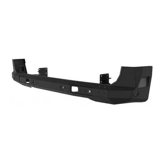
S PRI NTER VAN R E AR B UM PE R
SP1130 B
INSTALLATION
GUIDE
F L AT L I N E VA N C O • S U P P O R T @ F L AT L I N EVA N C O . C O M • 8 8 8 - 6 6 7- 5 5 7 6
TOOLS REQUIRED
+
AUTO PANEL REMOVAL TOOLS
+
9/16" WRENCH & SOCKET
+
8MM WRENCH OR SOCKET
+
18MM WRENCH OR SOCKET
+
19MM WRENCH OR SOCKET
INSTALL INFO
TIME TO INSTALL THIS PRODUCT: 2-3 HOURS
Additional help is suggested for a few of the install steps.
BEFORE YOU START
Please inspect the product and packaging upon
delivery to ensure there are no issues and that
all parts and hardware are accounted for.
Contact us ASAP if anything is missing at:
support@flatlinevanco.com
(NOT INCLUDED)
0 1
Advertisement

Related Manuals for FVC SP1130B


Summary of Contents for FVC SP1130B
- Page 1 INSTALLATION GUIDE S PRI NTER VAN R E AR B UM PE R SP1130 B TOOLS REQUIRED (NOT INCLUDED) AUTO PANEL REMOVAL TOOLS 9/16” WRENCH & SOCKET 8MM WRENCH OR SOCKET 18MM WRENCH OR SOCKET 19MM WRENCH OR SOCKET INSTALL INFO TIME TO INSTALL THIS PRODUCT: 2-3 HOURS Additional help is suggested for a few of the install steps.
-
Page 2: Before You Start
BEFORE YOU START All Flatline Van Co products must be properly assembled and secured before attaching to your vehicle. Improper attachment could result in an automobile accident, and could cause serious bodily injury or death to you or to others involved. You are responsible for assembling and securing Flatline Van Co products to your vehicle, checking the mounting points and attachments prior to use, and regularly inspecting the products for wear and or damage. - Page 3 BUMPER PACKAGE CONTENTS PASSENGER SIDE BUMPER REAR BUMPER ASSEMBLY DRIVER SIDE BUMPER BRACKET BRACKET QTY: 1 QTY: 1 QTY: 1 PASSENGER SIDE FRAME DRIVER SIDE FRAME SPRINTER PARK SENSOR BRACKET WELDMENT BRACKET WELDMENT BEZEL QTY: 1 QTY: 6 QTY: 1 F L AT L I N E VA N C O •...
- Page 4 BUMPER HARDWARE 3/8-16 NYLON INSERT 3/8-16 X 1 BUTTON HEAD 0.5-13 NYLON LOCKNUT 3/8 SCREW FLAT WASHER LOCKNUT HEX DRIVE SCREW QTY: 12 QTY: 8 QTY: 12 QTY: 12 M12-1.75 x 110mm HEX M12-1.75 NYLON M12 SCREW FLAT 0.5-13 x 1.5 HEX HEAD HEAD SCREW LOCKNUT WASHER...
- Page 5 INSTALL TOOLS REQUIRED FOR THIS STEP: STEP | 01 LAYOUT AND INSTALL PREP 1.1 Safety Check: Disconnect battery (both if applicable) prior to performing any electrical work and ensure you are working on a flat surface. 1.2 Review Install Outllne: Thoroughly read all instructions and warnings before beginning installation.
- Page 6 TOOLS REQUIRED FOR THIS STEP: AUTO PANEL PRY TOOL STEP | 02 REMOVE FACTORY BUMPER UPPER REAR BUMPER TRIM REAR SIDE TRIM 2.1 Access Upper Rear Bumper Trim: Using an Auto Panel Pry Tool, unclip the Rear Side Trim from the body to gain access to the plastic rivets that hold the Upper Rear Bumper Trim to the van body (FIG 3).
- Page 7 TOOLS REQUIRED FOR THIS STEP: AUTO PANEL PRY TOOL STEP | 02 REMOVE FACTORY BUMPER 2.4 Underside Plastic Rivets and Clips: Remove the plastic rivets and clips on the lower side of the bumper cover. There are two rivets on each outer side, two clips on the corners and two more rivets toward the center of the Factory Bumper Cover (FIG 6-8).
- Page 8 T40 TORX TOOLS REQUIRED FOR THIS STEP: RATCHET RATCHET EXTENSION FLATHEAD SCREWDRIVER STEP | 02 REMOVE FACTORY BUMPER 2.5 Remove Torx Bolts: Remove the (7) Torx Bolts holding the Factory Bumper Cover to the body. These are located just under the rear door weather strip and become visible once you open the rear doors (FIG 9-10).
- Page 9 T40 TORX TOOLS REQUIRED FOR THIS STEP: RATCHET RATCHET EXTENSION STEP | 02 REMOVE FACTORY BUMPER 2.7 Remove Factory Bumper Cover: The bumper cover can now be removed. Take care to note the orientation and position of the park sensors, as they will need to be reinstalled to the new bumper as they were in the Factory Bumper Cover.
- Page 10 TOOLS REQUIRED FOR THIS STEP: 7/32” ALLEN WRENCH 9/16” WRENCH OR SOCKET STEP | 03 PREP FVC BUMPER INSTALL 3.1 Install Bumper Brackets: Install the Driver and Passenger Side Bumper Brackets using (6ea) 3/8-16 x0.75 Button Head Hex Drive Screws, Flat Washers and Nylon Locknuts (FIG 14- 15).
- Page 11 TOOLS REQUIRED FOR THIS STEP: STEP | 03 PREP FVC BUMPER INSTALL 3.2 Install Park Sensor Bezels: Install the plastic Park Sensor Bezels to the locations shown in FIG 16. Install by aligning the notches in the Park Sensor Bezel to the cutouts in the Bumper (FIG 17).
- Page 12 TOOLS REQUIRED FOR THIS STEP: STEP | 03 PREP FVC BUMPER INSTALL 3.4 Install Blind Spot Sensor (Passenger Side): Install the Blind Spot Sensor to the bracket shown in FIG 19. 3.5 Install Park Sensors to Park Sensor Bezels (Passenger Side): Install the Park Sensors to the Park Sensor Bezels in the orientation that they were removed as shown in FIG 20.
- Page 13 TOOLS REQUIRED FOR THIS STEP: STEP | 03 PREP FVC BUMPER INSTALL 3.6 Install Blind Spot Sensor (Driver Side): Install the Blind Spot Sensor to the bracket shown in FIG 21. 3.7 Install Park Sensors to Park Sensor Bezels (Driver Side): Install the Park Sensors to the Park Sensor Bezels in the orientation that they were removed as shown in FIG 22.
- Page 14 TOOLS REQUIRED FOR THIS STEP: STEP | 03 PREP FVC BUMPER INSTALL 3.8 Install Off-Road Lights (Optional): If you purchased Off- Road Lights for this Rear Bumper, install them to the Light Brackets shown in FIG 23-24 at this time.
- Page 15 TOOLS REQUIRED FOR THIS STEP: 18MM WRENCH OR SOCKET 19MM WRENCH OR SOCKET STEP | 04 FVC BUMPER INSTALL 4.1 Install Van Frame Brackets: Install the Van Frame Brackets to the locations shown in FIG 25-26 by removing the factory bolts and replacing them one-at-a-time with M12-1.75 x 110mm...
- Page 16 TOOLS REQUIRED FOR THIS STEP: 8MM WRENCH OR SOCKET STEP | 04 FVC BUMPER INSTALL 4.2 Install Rear Bumper to Van Frame Brackets: Install the Rear Bumper to the Van Frame Brackets using (4ea) 0.5-13 x 1.5 Hex Head Screws, Flat Washers and Nylon Locknuts (FIG 27-28).
- Page 17 FVC (and see) from you! Head to the products and following along and we will make it right. FVC is product page and click “Leave a company of van and outdoor with your adventures. Tag us Review.”...
Need help?
Do you have a question about the SP1130B and is the answer not in the manual?
Questions and answers