
Subscribe to Our Youtube Channel
Related Manuals for Cincoze DS-1400 Series


Summary of Contents for Cincoze DS-1400 Series
- Page 1 DS-1400 Series User Manual Rugged Embedded Computer 12th Generation Intel® Core™ Series Processors, High Performance, Expandable and Modular Rugged Embedded Computer Version: V1.00...
-
Page 2: Table Of Contents
2.5 Optional Module Pin Definition & Settings ................34 2.5.1 CMI-M12LAN01-R12/UB1010 Module ..............34 2.5.2 CMI-XM12LAN01-R12/UB1030 Module ..............34 2.5.3 CMI-DIO02/UB1018 Module ..................35 2.5.4 CMI-COM02/UB1004 Module ................... 36 2.5.5 CMI-ICOM01/UB1004 Module .................. 37 2.5.6 CFM-IGN101 Module ....................38 DS-1400 Series | User Manual... - Page 3 Chapter 4 BIOS Setup ......................... 98 4.1 BIOS Introduction ......................... 99 4.2 Main Setup ......................... 100 4.3 Advanced Setup ......................... 101 4.3.1 CPU Configuration ....................101 4.3.2 Power & Performance ..................... 103 4.3.3 SATA Configuration ....................103 DS-1400 Series | User Manual...
- Page 4 4.7.8 Save as User Defaults ....................121 4.7.9 Restore User Defaults....................121 4.8 MEBx ..........................122 Chapter 5 Product Application ......................125 5.1 Where to download drivers? ..................... 126 5.2 Where to find the technical documents? ................126 DS-1400 Series | User Manual...
-
Page 5: Preface
2023/08/31 Copyright Notice © 2023 by Cincoze Co., Ltd. All rights are reserved. No parts of this manual may be copied, modified, or reproduced in any form or by any means for commercial use without the prior written permission of Cincoze Co., Ltd. All information and specification provided in this manual are for reference only and remain subject to change without prior notice. -
Page 6: Product Warranty Statement
(such as a fuse, battery, etc.), are not warranted. Before sending your product in, you will need to fill in Cincoze RMA Request Form and obtain a RMA number from us. Our staff is available at any time to provide you with the most friendly and immediate service. -
Page 7: Limitation Of Liability
Limitation of Liability Cincoze’ liability arising out of the manufacture, sale, or supplying of the product and its use, whether based on warranty, contract, negligence, product liability, or otherwise, shall not exceed the original selling price of the product. The remedies provided herein are the customer’s sole and exclusive remedies. -
Page 8: Safety Precautions
14. CAUTION: Risk of Explosion if Battery is replaced by an Incorrect Type. Dispose of Used Batteries According to the Instructions. ATTENTION: Risque d'explosion si la batterie est remplacée par un type incorrect. Mettre au DS-1400 Series | User Manual... -
Page 9: Ordering Information
12th Generation Intel Core Series Processors, High Performance, Expandable DS-1401-R10 and Modular Rugged Embedded Computer with 1x PCI/PCIe Expansion Slot 12th Generation Intel Core Series Processors, High Performance, Expandable DS-1402-R10 and Modular Rugged Embedded Computer with 2x PCI/PCIe Expansion Slot DS-1400 Series | User Manual... -
Page 10: Chapter 1 Product Introductions
Chapter 1 Product Introductions DS-1400 Series | User Manual... -
Page 11: Overview
I/O interfaces and robust functionalities. To meet various application needs, it can flexibly expand the required I/O and specific functions through Cincoze’s unique CMI, CFM, and MEC expansion modules. Moreover, the DS-1400 has passed multiple international certifications, ensuring stable and reliable performance in diverse harsh environments. - Page 12 DS-1400 Series | User Manual...
-
Page 13: Specifications
1x Line-out, Phone Jack 3.5mm • Mic-in 1x Mic-in, Phone Jack 3.5mm • 2x GbE LAN, RJ45 - GbE1: Intel® I219 - GbE2: Intel® I210 • 2x RS-232/422/485 with Auto Flow Control (Supports 5V/12V), DB9 DS-1400 Series | User Manual... - Page 14 Remote Power On/Off 1x Remote Power On/Off, 2-pin Terminal Block • Remote Power LED 1x Remote Power LED, 2-pin Terminal Block Physical • Dimension (W x D x H) 227 x 261 x 88 mm (DS-1400) DS-1400 Series | User Manual...
- Page 15 • Linux Supports by project * Product Specifications and features are for reference only and are subject to change without prior notice. For more information, please refer to the latest product datasheet from Cincoze's website. DS-1400 Series | User Manual...
-
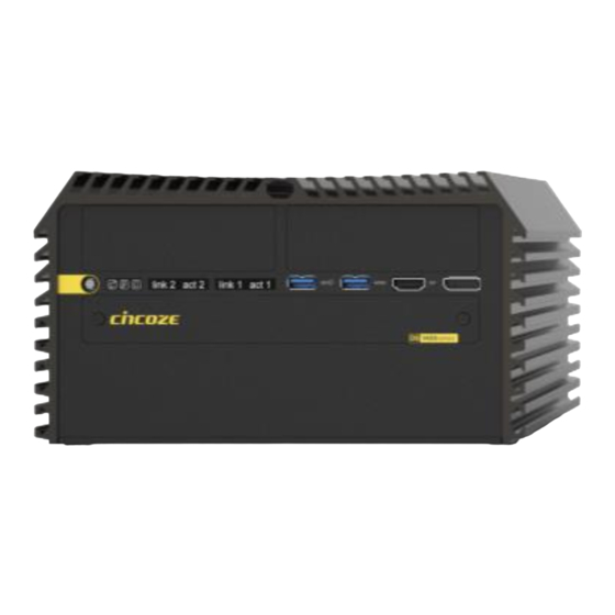
Page 16: External Layout
1.3 External Layout 1.3.1 Front DS-1400 DS-1401 DS-1402 DS-1400 Series | User Manual... -
Page 17: Rear
1.3.2 Rear DS-1400 DS-1401 DS-1402 DS-1400 Series | User Manual... -
Page 18: Dimensions
1.4 Dimensions DS-1400 Unit: mm DS-1401 Unit: mm DS-1400 Series | User Manual... - Page 19 DS-1402 Unit: mm DS-1400 Series | User Manual...
-
Page 20: Chapter 2 Introduction To Switches And Connectors
Chapter 2 Introduction to Switches and Connectors DS-1400 Series | User Manual... -
Page 21: Location Of Switches And Connectors
2.1 Location of Switches and Connectors 2.1.1 Top View DS-1400 Series | User Manual... -
Page 22: Bottom View
2.1.2 Bottom View DS-1400 Series | User Manual... -
Page 23: Switches And Connectors Definition
M.2 Key M Socket (Support AHCI or NVMe PCIe / SATA Storage) PCIE1 PCI-Express X16 Socket PCIE2 PCI-Express X1 Socket /FAN USB2_13_1 Internal USB 2.0 Ports DDR5 DDR5 SODIMM Socket IGN_PH1 IGN Board to Board connector SIM1, SIM2 SIM Card Socket DS-1400 Series | User Manual... - Page 24 AT_ATX1 AT / ATX Power Mode Switch RESET Reset button PWR_SW1 Power Switch DC_IN2 4-Pin DC Out BIOS SPI interface (Optional) RTC Battery board to board connector DS-1400 Series | User Manual...
-
Page 25: Definition Of Switches
SW2: SATA DOM / COM1 / COM2 Power Select Location Function DIP1 DIP2 Disable ON (Default) SATA Enable Location Function DIP3 DIP4 0V(RI) ON (Default) ON (Default) COM1 Location Function DIP5 DIP6 0V(RI) ON (Default) ON (Default) COM2 DS-1400 Series | User Manual... - Page 26 Push Reset System AT_ATX: AT / ATX Power Mode Switch Switch Definition Left AT Power Mode Right ATX Power Mode (Default) JP2: Clear BIOS Switch Definition 1-2 (Left) Normal Status (Default) 2-3 (Right) Clear BIOS DS-1400 Series | User Manual...
-
Page 27: Definition Of Connectors
2.4 Definition of Connectors CN5:Mini PCI-Express Socket (Support mPCIE/ mSATA) Definition Definition WAKE# 3.3V +1.5V SMB_CLK PETN/SATATN 1.5V SMB_DATA CLKREQ# PETP/SATATP USB_D- REFCLK- USB_D+ REFCLK+ 3.3V 3.3V 3.3V PERST# +1.5V PERN/SATARP +3.3VAUX PERP/SATARN +3.3V DS-1400 Series | User Manual... - Page 28 CN6:Mini PCI-Express Socket (Support mPCIE/ mSATA) Definition Definition WAKE# 3.3V +1.5V SMB_CLK PETN/SATATXN 1.5V SMB_DATA PETP/SATATXP USB_D- USB_D+ 3.3V 3.3V 3.3V PERST# +1.5V PERN/SATARXP 3.3V PERPSATARXN +3.3V DS-1400 Series | User Manual...
- Page 29 CN7:Mini PCI-Express Socket (Support mPCIE/ mSATA / USB3 + 4G module) Definition Definition WAKE# 3.3V +1.5V SMB_CLK PETN/SATATN/USB3TN 1.5V SMB_DATA UIM_RST2 PETP/SATAP/USB3TP SIM_PWR1 SIM_DATA1 USB_D- REFCLK- RESERVED SIM_CLK USB_D+ REFCLK+/SIM_PWR2 RESERVED SIM_Reset1 3.3V SIM_VPP1 SIM_CLK2 SIM_DATA2 3.3V PERST# +1.5V PERN/SATARP/USB3RN 3.3V PERP/SATARN/USB3RP +3.3V DS-1400 Series | User Manual...
- Page 30 PEWAKE# PERN1 REFCLKP +3.3V PERN3 PERP1 PERP3 PETN1 PETN3 PETP1 +3.3V DEVSLP PETP3 +3.3V SMB_CLK PERN0/SATARP0 +3.3V SMD_DATA SUSCLK PERN2 PERP0/SATARN0 PEDET +3.3V ALERT# +3.3V PERP2 +3.3V CFG0 PETN0/SATATN0 +3.3V PETN2 PETP0/SATATP0 CFG2 RESET# PETP2 DS-1400 Series | User Manual...
- Page 31 (Ne mettez pas sous tension ce connecteur! Ce port est utilisé pour connecter un SWITCH!) FAN1: CPU Smart Fan Connector Connector Type: Terminal Block 1X4 4-pin, 3.5mm pitch Definition +12V 2 3 4 SENSE Control DS-1400 Series | User Manual...
- Page 32 Please disconnect the power source before mounting the DC power cables or connecting the DC power connector to system. (Veuillez débrancher la source d'alimentation avant de monter les câbles d'alimentation CC ou de connecter le connecteur d'alimentation CC au système.) DS-1400 Series | User Manual...
- Page 33 LAN LED Status Definition Link LED Status Definition Steady Green 1 Gbps Network Link Steady Orange 100 Mbps Network Link 10 Mbps Network Link Act LED Status Definition Blinking Yellow Data Activity Steady Yellow No Activity DS-1400 Series | User Manual...
-
Page 34: Optional Module Pin Definition & Settings
CMI-M12 LAN Module Pin Definitions Connector Type: M12 A coded 8pin connector Definition Definition 2_LAN1_0+ 2_LAN1_0- 2_LAN1_1+ 2_LAN1_2+ 2_LAN1_2- 2_LAN1_1- 2_LAN1_3+ 2_LAN1_3- 2.5.2 CMI-XM12LAN01-R12/UB1030 Module CMI-XM12LAN01 Module Pin Definitions Connector Type: M12 X coded 8pin connector Definition Definition DS-1400 Series | User Manual... -
Page 35: Cmi-Dio02/Ub1018 Module
2.5.3 CMI-DIO02/UB1018 Module DIO1: Digital Input / Output Connector Connector Type: Terminal Block 2X5 10-pin, 3.5mm pitch Definition Definition XCOM+ XCOM- (DC INPUT) (GND) Definition Definition 2XCOM+ 2XCOM- (DC INPUT) (GND) DS-1400 Series | User Manual... -
Page 36: Cmi-Com02/Ub1004 Module
ON (Default) ON (Default) COM3 Location Function DIP3 DIP4 0V(RI) ON (Default) ON (Default) COM4 Location Function DIP5 DIP6 0V(RI) ON (Default) ON (Default) COM5 Location Function DIP7 DIP8 0V(RI) ON (Default) ON (Default) COM6 DS-1400 Series | User Manual... -
Page 37: Cmi-Icom01/Ub1004 Module
2.5.5 CMI-ICOM01/UB1004 Module COM3~COM6:RS232 Connector Connector Type: 9-pin D-Sub RS232 Definition COM3/4/5/6 are isolated COM, each pin5 (GND) is independent. (COM3/4/5/6 sont des COM isolés, chaque pin5 (GND) est indépendant.) DS-1400 Series | User Manual... -
Page 38: Cfm-Ign101 Module
Default setting of Pin1 to Pin4 is OFF / OFF / OFF / OFF. 24V_12V_1:IGN Module Voltage Mode Setting Switch 12V / 24V Car Battery Switch Switch Definition Left 12V Car Battery Input Right 24V Car Battery Input (Default) DS-1400 Series | User Manual... -
Page 39: Chapter 3 System Setup
Chapter 3 System Setup DS-1400 Series | User Manual... -
Page 40: Removing Top Cover
Turn over the unit to have the bottom side face up, loosen the 6 screws on the bottom cover and place them aside for later use. Step 2. Remove the bottom cover from the chassis. DS-1400 Series | User Manual... - Page 41 Unscrew the 2 screws at the rear bezel as indicated and place them aside for later use. Step 4. Loosen the 4 screws. Pull out the 4 latches as marked. Step 5. Lift up the unit vertically by holding the front and rear panel. DS-1400 Series | User Manual...
-
Page 42: Installing Cpu
Step 6. Turn over the body of the unit and place it gently. 3.2 Installing CPU Step 1. Locate the CPU socket. DS-1400 Series | User Manual... - Page 43 Step 2. Pull up the lever. Step 3. Lift up the holder. Step 4. Align the CPU with the fool-proof protrusions on the socket and put on the CPU. DS-1400 Series | User Manual...
- Page 44 Make sure that the CPU is clean, and apply the thermal paste onto the center of the CPU’s surface as shown below. For more information about the thermal paste application, please find the Intel official website. DS-1400 Series | User Manual...
-
Page 45: Installing So-Dimm
Place the CPU heatsink on with aligning the four mounting holes of the heatsink and the nut studs and then fasten the heatsink with the provided 4 screws. 3.3 Installing SO-DIMM Step 1. Turn the system to the bottom side. Unscrews the 4 screws and remove the bracket. DS-1400 Series | User Manual... - Page 46 Insert the SO-DIMM at a 45-degree angle until its edge connector is connected to the SO-DIMM socket firmly. 45° 45° Upper socket Lower socket Step 4. Press down the module until the retaining clips snap back in place. Upper socket Lower socket DS-1400 Series | User Manual...
-
Page 47: Installing Mini-Pcie Card
Locate the Mini PCIe socket CN7 on the top side and CN5/CN6 on the bottom side of the system. Step 2. Use provided two screws fasten the half size module and adapter bracket together as shown in Fig (a) below. (a) Half Size Mini-PCIe Card (b) Full Size Mini-PCIe Card DS-1400 Series | User Manual... -
Page 48: Installing M.2 M Key Card
Step 4. Press the card down and secure it with 2 screws. 3.5 Installing M.2 M Key Card Step 1. Turn the system to the bottom side, and locate the M.2 M Key slot (CN8). DS-1400 Series | User Manual... -
Page 49: Installing Antenna
Step 3. Press the card down and secure it with the screw. 3.6 Installing Antenna Step 1. Remove the antenna rubber cover on the rear panel. Step 2. Penetrate the antenna jack through the hole. DS-1400 Series | User Manual... - Page 50 Step 3. Put on the washer and fasten the nut of antenna jack. Step 4. Assemble the antenna and antenna jack together. Step 5. Attach the RF connector of the cable’s another end onto the card. DS-1400 Series | User Manual...
-
Page 51: Installing Sata Hard Drive On Top Side
4 screws to assemble HDD and HDD bracket together. Step 3. Turn over the HDD bracket. Connect the HDD bracket to the SATA connector and fasten the 3 screws. DS-1400 Series | User Manual... -
Page 52: Installing Pci/Pcie Add-On Card
3.8 Installing PCI/PCIe Add-on Card (For DS-1401 and DS-1402 only) The applicable riser cards for DS-1400 series are listed in the following table. Model No. Description Compatible Model RC-E16-01 Riser Card with 1 x PCIex16 Slot DS-1401 RC-PI-01 Riser Card with 1 x PCI Slot... - Page 53 Assemble the riser card with extension bracket together and fasten with the 4 screws. Step 4. (1) Loosen the screw(s) to remove I/O bracket(s). (2) Loosen the screws halfway to allow the card retainer to be adjustable. DS-1400 Series | User Manual...
- Page 54 (1) Insert PCI(e) add-on card to the slot. (2) Fasten the screw to secure it Step 6. (1) Push the card retainer forward to against the edge of the add-on card. (2) Fasten the screws to fix the card retainer. DS-1400 Series | User Manual...
- Page 55 Step 7. Locate the riser card slot on bottom side of system. Step 8. Install the module assembled in step 6 into the riser card slot, and fasten the 4 screws to secure it. DS-1400 Series | User Manual...
-
Page 56: Assembling Top Cover
Lift the body of the unit, make sure that the front and rear panels are in the chassis groves, and then assemble the body into the chassis. Step 3. Push into the 4 latches as indicated and fasten the 4 screws. DS-1400 Series | User Manual... - Page 57 Fasten the 2 screws at rear panel. Step 5. Be sure to align the grooves with fzront and rear panels. Put the bottom cover back on and fasten the 6 screws to fix the cover. DS-1400 Series | User Manual...
-
Page 58: Installing Sata Hard Drives At Front Panel
Pull the rotating arm and pull the HDD bracket out of system. Step 4. Make HDD bottom side face up, place the HDD bracket on it. Ensure the direction of bracket is correct and use 4 provided screws to assemble HDD and HDD bracket together. DS-1400 Series | User Manual... - Page 59 HDD connector is fully inserted into the SATA slot. Step 6. Place the rotating arm back and fasten the screw. Step 7. Fix the cover plate of maintenance zone by fastening the two screws. DS-1400 Series | User Manual...
-
Page 60: Installing Sim Card
Please pay attention to the insert orientation as illustrated. (When SIM cards are inserted into both sockets, the network connection will prioritize SIM1.) Step 3. Fix the cover plate of maintenance zone by fastening the two screws. DS-1400 Series | User Manual... -
Page 61: Replacing Cmos Battery
Locate the removable CMOS Battery and loosen the screw. Step 3. Pull out the CMOS battery bracket with assistance of a tweezer. Step 4. Remove the battery by pressing the metal tab backwards slightly as indicated. DS-1400 Series | User Manual... - Page 62 "-" side and pull the metal tab backwards to make the battery fully installed in the slot. Step 6. Insert the battery bracket firmly. Step 7. Fasten the screw. Step 8. Fix the cover plate of maintenance zone by fastening the two screws. DS-1400 Series | User Manual...
-
Page 63: Installing Wall Mount
3.13 Installing Wall Mount DS-1400 series offers wall mount kit that customers can install the system on the wall in a convenient and economical way. Step 1. The mounting holes are at the bottom side of the system. Use the provided 8 screws to fasten the bracket and the system together. - Page 64 Step 2. Fasten the screws through the bracket mounting holes to mount the system onto the wall. DS-1400 Series | User Manual...
-
Page 65: Connecting To Power Supply
In formal use, please use new Phoenix contacts and make sure the screws are tightened to avoid poor connection. (En utilisation formelle, veuillez utiliser de nouveaux contacts Phoenix et assurez-vous que les vis sont bien serrées pour éviter une mauvaise connexion.) DS-1400 Series | User Manual... -
Page 66: Installing Cmi Modules
Loosen the 2 hex nuts from back side of front bezel. Remove the front bezel. Step 2. Attach the CMI-LAN bracket, and fasten the 2 hex nuts to fix it as indicated. Step 3. Locate the connector(s) of CMI-LAN module on top side of system. BTB_FH1 BTB_FH4 DS-1400 Series | User Manual... -
Page 67: Cmi-M12Lan01-R12/Ub1010 Module
CMI-M12LAN01-R12/UB1010 Module Step 1. Loosen the 2 hex nuts from back side of front bezel. Remove the front bezel. Step 2. Attach the CMI-M12LAN bracket, and fasten the 2 hex nuts to fix it as indicated. DS-1400 Series | User Manual... - Page 68 Step 5. Penetrate the CMI-M12LAN ports through the holes on the bracket. Insert the CMI module vertically into the female connector on system’s mainboard until it’s connected firmly and fasten 4 screws to fix it. DS-1400 Series | User Manual...
-
Page 69: Cmi-Xm12Lan01-R10/Ub1030 Module
Step 6. Fasten the four hex rings to fix the cover plate. 3.15.3 CMI-XM12LAN01-R10/UB1030 Module Hex washers M12 I/O bracket Hex rings Rubber rings DS-1400 Series | User Manual... - Page 70 Penetrate hex rings through the M12 I/O bracket holes, and fix them with hex washers. Step 2. Loosen the 2 hex nuts from back side of front bezel. Remove the front bezel. Step 3. Locate the connector(s) of CMI-M12LAN module on top side of system. BTB_FH1 BTB_FH4 DS-1400 Series | User Manual...
- Page 71 4 screws to fix it. Step 5. Attach the assembled M12 I/O bracket on to the system, and fasten the hex nuts to fix it. Step 6. Put on the rubber rings to the four M12 LAN ports. DS-1400 Series | User Manual...
-
Page 72: Cmi-10Glan03-R10/Ub1028 Module
Selection] setting from default mode [4x1] to mode [1x4]. Step 1. Loosen the 2 hex nuts from back side of front bezel. Remove the front bezel. Step 2. Attach the CMI-10GLAN bracket, and fasten the 2 hex nuts to fix it as indicated. DS-1400 Series | User Manual... - Page 73 Before putting on the heatsink (in the next step), please make sure the protective film on the Thermal Pad has been removed! (Avant de mettre le bloc thermique (à l'étape suivante), veuillez vous assurer que le film protecteur sur le coussin thermique a été retiré!) DS-1400 Series | User Manual...
- Page 74 Before assembling the system’s chassis cover, please make sure the protective film on the Thermal Pad has been removed! (Avant d'assembler le couvercle du châssis du système, assurez-vous que le film protecteur sur le coussin thermique a été retiré !) DS-1400 Series | User Manual...
-
Page 75: Cmi-Dio02/Ub1018 Module
Loosen the 2 hex nuts from back side of front bezel. Remove the front bezel. Step 2. Attach the CMI-DIO bracket, and fasten the 2 hex nuts to fix it as indicated. Step 3. Locate the connector(s) of CMI-DIO module on top side of system. DS-1400 Series | User Manual... -
Page 76: Cmi-Com02/Ub1004 Module
Locate the connector(s) of the CMI-COM module on the top side of the system. Choose one connector to install the module. DS-1400 series supports one CMI-COM module installed on the system at most. (La série DS-1400 prend en charge au maximum un module CMI-COM installé sur le système.) - Page 77 2 screws to fix it. Step 4. Attach the CMI-COM bracket, and fasten the 2 hex nuts to fix it as indicated. Step 5. Fasten the 8 D-Sub jack screws to fix the module. DS-1400 Series | User Manual...
-
Page 78: Cmi-Icom01/Ub1004 Module
Locate the connector(s) of the CMI-ICOM module on the top side of the system. Choose one connector to install the module. DS-1400 series supports one CMI-ICOM module installed on the system at most. (La série DS-1400 prend en charge au maximum un module CMI-ICOM installé sur le système.) - Page 79 Step 4. Attach the CMI-ICOM bracket, and fasten the 2 hex nuts to fix it as indicated. Step 5. Fasten the 8 D-Sub jack screws to fix the module. DS-1400 Series | User Manual...
-
Page 80: Installing Cfm Modules
Penetrate the CMI-M12LAN ports through the holes on the bracket. Insert the CMI module vertically into the female connector on system’s mainboard until it’s connected firmly and fasten 4 copper pillars to fix CMI-M12LAN module. DS-1400 Series | User Manual... - Page 81 Before putting on the heatsink (in the next step), please make sure the protective film on the Thermal Pad has been removed! (Avant de mettre le bloc thermique (à l'étape suivante), veuillez vous assurer que le film protecteur sur le coussin thermique a été retiré!) DS-1400 Series | User Manual...
- Page 82 (Avant d'assembler le couvercle du châssis du système, assurez-vous que le film protecteur sur le coussin thermique a été retiré !) Once the steps are finished, after system power on, PoE LED (on CMI-LAN or CMI-M12 LAN module) will light blue as shown below. DS-1400 Series | User Manual...
- Page 83 DS-1400 Series | User Manual...
-
Page 84: Cfm-Ign101 Module
Insert the connector of IGN module to the female connector on system motherboard. (Make sure all the pins of IGN module’s connector are firmly connected.) Step 3. Fasten the two screws to secure the power ignition board. DS-1400 Series | User Manual... -
Page 85: Installing Mec Modules
DS-1400 or DS-1401 system. For more detailed information, please refer to the Ordering Information section of the DS-1400 or DS-1401 datasheet.) Step 2. Attach the MEC-COM brackets, and fasten the 4 screws to fix it as indicated. DS-1400 Series | User Manual... - Page 86 Tilt the Mini PCIe card at a 45-degree angle and insert it to the socket until the golden finger connector of the card seated firmly. 45° Step 5. Press the card down and secure it with 2 screws. DS-1400 Series | User Manual...
- Page 87 Connect the other end of the wire to the Mini PCIe card as indicated. Step 8. Attach the COM ports onto the back side of the cover plates, and then fasten the 4 D-Sub jack screws to secure the COM ports. DS-1400 Series | User Manual...
-
Page 88: Mec-Usb-M102-30/Ub0314 Module
Attach the MEC-USB bracket, and fasten the 2 screws to fix it as indicated. Step 3. Locate one of the Mini PCIe sockets on the bottom side of the system. In this chapter, we use CN6 for example. DS-1400 Series | User Manual... - Page 89 Tilt the Mini PCIe card at a 45-degree angle and insert it to the socket until the golden finger connector of the card seated firmly. 45° Step 5. Press the card down and secure it with 2 screws. Step 6. Connect the attached wire to the USB board. DS-1400 Series | User Manual...
- Page 90 Connect the other end of the wire to the Mini PCIe card as indicated. Step 8. Attach the USB board onto the back side of the cover plate, and then fasten the two screws to secure the module. DS-1400 Series | User Manual...
-
Page 91: Mec-Lan-M102-30/Ub0311 Module
Attach the MEC-LAN bracket, and fasten the 2 screws to fix it as indicated. Step 3. Locate one of the Mini PCIe sockets on the bottom side of the system. In this chapter, we use CN6 for example. DS-1400 Series | User Manual... - Page 92 Tilt the Mini PCIe card at a 45-degree angle and insert it to the socket until the golden finger connector of the card seated firmly. 45° Step 5. Press the card down and secure it with 2 screws. Step 6. Connect the attached wires to the LAN board. DS-1400 Series | User Manual...
- Page 93 Step 7. Connect the wires to the Mini PCIe card as indicated. Step 8. Attach the LAN board onto the back side of the cover plate, and then fasten the two screws to secure the module. DS-1400 Series | User Manual...
-
Page 94: Installing External Fan
Prepare an external fan. Loosen the 2 screws halfway on mounting frame before attempting to install it. Step 2. Slide the FAN into the middle groove of chassis as illustrated. Tighten the 2 screws to fix it onto chassis. DS-1400 Series | User Manual... - Page 95 Step 3. Move the fan to the center of chassis. Tighten the 2 screws marked on photo to secure it. Step 4. Connect the FAN cable to external fan power connector at rear panel. DS-1400 Series | User Manual...
-
Page 96: Installing Internal Fan
Unscrew 6 screws to remove 3 I/O brackets from rear panel. Step 2. Insert the fan connector to the power connector (power4). Step 3. Attach the FAN from back side of rear panel, and then fasten the 4 screws to fix it. DS-1400 Series | User Manual... - Page 97 Step 4. User can use cable ties to tie the wire from the cut holes as indicated. DS-1400 Series | User Manual...
-
Page 98: Chapter 4 Bios Setup
Chapter 4 BIOS Setup DS-1400 Series | User Manual... -
Page 99: Bios Introduction
( ↑↓ ) to highlight the field and press <Enter> to call up the sub-menu. Then you can use the control keys to enter values and move from field to field within a sub-menu. If you want to return to the main menu, just press the <Esc >. DS-1400 Series | User Manual... -
Page 100: Main Setup
Use arrow keys to move among the items and press <Enter> to accept or enter a sub-menu. 4.2.1 System Date Set the date. Please use <Tab> to switch between date elements. 4.2.2 System Time Set the time. Please use <Tab> to switch between time elements. DS-1400 Series | User Manual... -
Page 101: Advanced Setup
4.3 Advanced Setup 4.3.1 CPU Configuration DS-1400 Series | User Manual... - Page 102 With virtualization, one computer system can function as multiple virtual systems. ■ Active Performance-cores [All] Allows users to choose the number of active performance cores. Configuration options: [All] [1] [2] [3] [4] [5] ■ Hyper-threading Enables or disables for Hyper-Threading Technology. DS-1400 Series | User Manual...
-
Page 103: Power & Performance
■ SATA Controller(s) [Enabled] Enables or disables Serial ATA controller. ■ SATA Mode Selection [AHCI] This item only allows users to choose [AHCI] mode. ❑ Serial ATA Port 0 Port 0 [Enabled] Enables or disables SATA Port 0. DS-1400 Series | User Manual... -
Page 104: Pch-Fw Configuration
Enables or disables SATA Port 3. ❑ Serial ATA Port 4 Port 4 [Enabled] Enables or disables SATA Port 4. ❑ Serial ATA Port 5 Port 5 [Enabled] Enables or disables SATA Port 5. 4.3.4 PCH-FW Configuration DS-1400 Series | User Manual... -
Page 105: Trusted Computing
Allows users to enable or disable ME firmware image re-flash function. 4.3.5 Trusted Computing ■ Security Device Support [Enable] Allow users to enable or disable Security Device Support function. ■ SHA256 PCR Bank [Enabled] Enables or disables SHA256 PCR Bank function. DS-1400 Series | User Manual... -
Page 106: Acpi Settings
Allows users to select the highest Advanced Configuration Power Interface® (ACPI) sleep state that system will enter when suspend button is pressed. [Suspend Disabled]: Disables entering suspend state. [S3 (suspend to RAM)]: Enables suspend to RAM state. DS-1400 Series | User Manual... -
Page 107: F81966 Super Io Configuration
❑ Change Settings [Auto] This item allows users to change the address & IRQ settings of the specified serial port. ❑ Onboard Serial Port 1 Mode [RS232] This item allows users to select Serial Port Mode. DS-1400 Series | User Manual... -
Page 108: Hardware Monitor
■ External Smart Fan Configuration Allows users to setting external smart fan parameters. ■ Internal Smart Fan Function [Enabled] Enables or disables internal smart fan function. ■ Internal Smart Fan Configuration Allows users to setting internal smart fan parameters. DS-1400 Series | User Manual... -
Page 109: S5 Rtc Wake Settings
This item allows users to change the way to wake system from S5 state. [Fixed Time]: Set the specified time (HH:MM:SS) to wake system. [Dynamic Time]: Set the increase time from current time to wake system. 4.3.10 Serial Port Console Redirection DS-1400 Series | User Manual... -
Page 110: Usb Configuration
This item allows users to enable or disable XHCI (USB3.2) hand-off function. ■ USB Mass Storage Driver Support [Enabled] Enables or disables support for USB mass storage devices. 4.3.12 Network Stack Configuration ■ Network Stack [Disabled] Enables or disables UEFI Network Stack. DS-1400 Series | User Manual... -
Page 111: Csm Configuration
The screen allows users to select options for the NVMe configuration, and change the value of the selected option. If there is NVMe Device detected, the options will show as the NVMe Device is found. DS-1400 Series | User Manual... -
Page 112: Chipset Setup
4.4 Chipset Setup This section allows you to configure chipset related settings according to user’s preference. 4.4.1 System Agent (SA) Configuration DS-1400 Series | User Manual... - Page 113 Configuration options: [Auto] [IGFX] [PEG Slot] [PCIe] ❑ Internal Graphics [Auto] This item allows users to enable or disable Internal Graphics. When set to [Auto], it will detect by BIOS. Configuration options: [Auto] [Disabled] [Enabled] DS-1400 Series | User Manual...
- Page 114 ❑ PCI Express Root Port (CN8) ◼ PCI Express Root Port [Enabled] Allows you to enable or disable the PCI Express Port. ◼ PCIe Speed [Auto] Allows you to select PCI Express interface speed. Configuration options: [Auto] [Gen1] [Gen2] [Gen3]. DS-1400 Series | User Manual...
- Page 115 This item allows users to enable or disable Intel® Virtualization Technology for Directed I/O (VT-d) function. ■ Above 4GB MMIO BIOS assignment [Enabled] This item allows users to enable or disable Above 4GB MMIO BIOS assignment function. DS-1400 Series | User Manual...
-
Page 116: Pch-Io Configuration
❑ PCI Express Root Port (Slot x1) ◼ PCI Express Root Port [Enabled] Allows you to enable or disable the PCI Express Port. ◼ PCIe Speed [Auto] Allows you to select PCI Express interface speed. Configuration options: [Auto] [Gen1] [Gen2] [Gen3]. DS-1400 Series | User Manual... - Page 117 ❑ HD Audio [Enabled] Allows you to select HD Audio options. [Enabled]: HD Audio device is unconditionally enabled. [Disabled]: HD Audio device is unconditionally disabled. ■ LAN i219LM Controller [Enabled] Enables or disables i219LM LAN Controller. DS-1400 Series | User Manual...
- Page 118 Allows you to specify which power state system will enter when power is resumed after a power failure (G3 state). [Always on]: Enters to power on state. [Always off]: Enters to power off state. [Keep last state]: Enters to the last power state before a power failure. DS-1400 Series | User Manual...
-
Page 119: Security Setup
User Password controls access to the system at boot and to the BIOS Setup utility. 4.5.3 Security Boot ❑ Secure Boot [Disabled] Enable or disable Secure Boot function. ❑ Secure Boot Mode [Standard] Allows you to select Secure Boor Mode. Configuration options: [Standard] [Custom]. DS-1400 Series | User Manual... -
Page 120: Boot Setup
Allows users to select the power-on state for keyboard NumLock. 4.6.3 Quiet Boot [Disabled] Allows users to enable or disable Quiet Boot function. 4.6.4 Fast Boot [Disabled] Allows users to enable or disable Fast Boot function. DS-1400 Series | User Manual... -
Page 121: Save & Exit
4.7.8 Save as User Defaults This item allows users to save the changes done so far as user defaults. 4.7.9 Restore User Defaults This item allows users to restore the user defaults to all the options. DS-1400 Series | User Manual... -
Page 122: Mebx
This page is for ME function setting. Press the delete key to enter the BIOS menu then user can see the following MEBx page. Press enter key to enter the default password "admin" to enter the next step for password creation. DS-1400 Series | User Manual... - Page 123 Create a new password using 8 characters including uppercase and lowercase letters, numbers and special symbols. Enter the created password again for confirmation. DS-1400 Series | User Manual...
- Page 124 Then you can see the function setting page of MEBx. DS-1400 Series | User Manual...
-
Page 125: Chapter 5 Product Application
Chapter 5 Product Application DS-1400 Series | User Manual... -
Page 126: Where To Download Drivers
5.1 Where to download drivers? Please go to the CINCOZE website to download the drivers for DS-1400 series. 5.2 Where to find the technical documents? Please go to the CINCOZE website to find the technical documents for DS-1400 series. Catalog... - Page 127 © 2023 Cincoze Co., Ltd. All rights reserved. The Cincoze logo is a registered trademark of Cincoze Co., Ltd. All other logos appearing in this catalog are the intellectual property of the respective company, product, or organization associated with the logo.
Need help?
Do you have a question about the DS-1400 Series and is the answer not in the manual?
Questions and answers