
Subscribe to Our Youtube Channel
Related Manuals for Cincoze DX-1200


Summary of Contents for Cincoze DX-1200
- Page 1 DX-1200 User Manual Rugged Embedded Computer 12th Gen. Intel® Core™ Series High Performance and Compact Rugged Embedded Computer Version: V1.00...
-
Page 2: Table Of Contents
3.4 Installing Mini-PCIe/mSATA Card ................... 41 3.5 Installing M.2 E Key Card ......................42 3.6 Installing Antenna(s) ......................43 3.6.1 For Antenna 1 or 2 ...................... 43 3.6.2 For Antenna 3 ......................45 3.7 Installing Top Cover ........................ 47 DX-1200 | User Manual... - Page 3 5.1.1 Digital I/O Programming Guide ................... 79 5.2 DIO Hardware Specification ....................86 Chapter 6 Optional Modules and Accessories ..................89 6.1 Pin Definition & Settings ......................90 6.1.1 CMI-M12LAN01-R12/ UB1710-R10 ................90 6.1.2 CMI-XM12LAN01-R10/ UB0930-R10 ................90 6.1.3 CMI-COM01/UB1303 ....................91 DX-1200 | User Manual...
- Page 4 6.4.2 CFM-IGN01 ........................ 110 6.5 Installing MEC Modules......................111 6.5.1 MEC-COM-M212-TDB9/UB1303 ................111 6.5.2 MEC-COM-M334-TDB9/2xUB1303 ................113 6.5.3 MEC-LAN-M102-30/UB1311 ..................115 6.6 Installing Optional Accessories .................... 117 6.6.1 SIDE-DX ........................117 6.6.2 DIN01 ........................118 6.6.3 FAN-EX101 ......................... 119 DX-1200 | User Manual...
-
Page 5: Preface
2023/05/05 Copyright Notice © 2023 by Cincoze Co., Ltd. All rights are reserved. No parts of this manual may be copied, modified, or reproduced in any form or by any means for commercial use without the prior written permission of Cincoze Co., Ltd. All information and specification provided in this manual are for reference only and remain subject to change without prior notice. -
Page 6: Product Warranty Statement
(such as a fuse, battery, etc.), are not warranted. Before sending your product in, you will need to fill in Cincoze RMA Request Form and obtain an RMA number from us. Our staff is available at any time to provide you with the most friendly and immediate service. -
Page 7: Technical Support And Assistance
Limitation of Liability Cincoze’ liability arising out of the manufacture, sale, or supplying of the product and its use, whether based on warranty, contract, negligence, product liability, or otherwise, shall not exceed the original selling price of the product. The remedies provided herein are the customer’s sole and exclusive remedies. -
Page 8: Conventions Used In This Manual
11. If the equipment is not used for a long time, disconnect it from the power source to avoid damage by transient overvoltage. 12. Never pour any liquid into an opening. This may cause fire or electrical shock. 13. Never open the equipment. For safety reasons, the equipment should be opened only by DX-1200 | User Manual... -
Page 9: Package Contents
DVI-I to VGA Adaptor Note: Notify your sales representative if any of the above items are missing or damaged. Ordering Information Model No. Product Description 12th Gen. Intel® Core Series High Performance and Compact Rugged DX-1200-R10 Embedded Computer DX-1200 | User Manual... - Page 10 DX-1200 | User Manual...
-
Page 11: Chapter 1 Product Introductions
Chapter 1 Product Introductions DX-1200 | User Manual... -
Page 12: Overview
1.1 Overview The DX-1200 is a fanless embedded computer that packs extreme performance into a rugged, compact chassis, making it the ideal choice for smart manufacturing, machine vision, and edge AI applications. A 12th gen Intel® Core™ (Alder Lake-S) processor (TDP up to 65W) and DDR5 4800 MHz memory provide high-speed computing performance, while additional functions, including rich native I/O and modular expansion design, meet the requirements for a wide range of applications. -
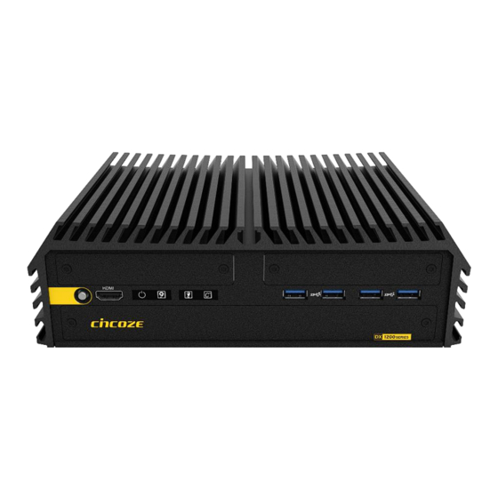
Page 13: Product Pictures
1x M.2 Key E Type 2230 Socket for Intel CNVi / Wireless Module ⚫ CMI Technology for Optional I/O Module Expansions ⚫ CFM Technology for Power Ignition Sensing & PoE Function ⚫ Wide Operating Temperature -40°C to 70°C ⚫ Safety Standard: UL, cUL, CB, IEC/EN62368-1 DX-1200 | User Manual... -
Page 14: Hardware Specification
• 1x DP Connector: 4096 x 2304 @ 60Hz * Verified maximum resolution: 3840 x 2160 @ 60Hz • 1x HDMI Connector: 3840 x 2160 @ 30Hz HDMI Audio • Realtek® ALC888, High Definition Audio Audio Codec • 1x Line-out, Phone Jack 3.5mm Line-out DX-1200 | User Manual... - Page 15 Reset Button • Support 0.2sec Instant Reboot Technology Instant Reboot • Software Programmable Supports 256 Levels System Reset Watchdog Timer Power • 1x ATX Power On/Off Button Power Button • 1x AT/ATX Mode Switch Power Mode Switch DX-1200 | User Manual...
- Page 16 • 65W TDP Processor: -40°C to 50°C (With External Fan Kit) Operating Temperature * With extended temperature peripherals; Ambient with air flow * According to IEC60068-2-1, IEC60068-2-2, IEC60068-2-14 • -40°C to 85°C Storage Temperature • 95% RH @ 70°C (Non-condensing) Relative Humidity • MIL-STD-810G(Pending) Shock DX-1200 | User Manual...
- Page 17 Safety • EN 45545-2 Fire Protection * Product Specifications and features are for reference only and are subject to change without prior notice. For more information, please refer to the latest product datasheet from Cincoze's website. DX-1200 | User Manual...
-
Page 18: System I/O
(High Speed CMI Interface) AT/ATX Mode Select Switch Used to customized I/O output with optional Used to select AT or ATX power mode modules 2.5” Hot Swap HDD/SSD Bay Used to insert a 2.5” SATA HDD/SSD DX-1200 | User Manual... -
Page 19: Rear
(Low Speed CMI Interface) Used to connect a monitor with DisplayPort interface Used to customized I/O output with optional DVI-I modules Used to connect a DVI monitor or connect optional split cable for dual display mode DX-1200 | User Manual... -
Page 20: Mechanical Dimension
1.7 Mechanical Dimension Unit: mm DX-1200 | User Manual... -
Page 21: Chapter 2 Switches & Connectors
Chapter 2 Switches & Connectors DX-1200 | User Manual... -
Page 22: Location Of Switches And Connectors
2.1 Location of Switches and Connectors 2.1.1 Top View DX-1200 | User Manual... -
Page 23: Bottom View
2.1.2 Bottom View DX-1200 | User Manual... -
Page 24: Switches And Connectors Definition
DIO or COM (COM5/COM6) Module Board to Board Connector SATA1 / SATA2 SATA Connector IGN_PH1 IGN Module Board to Board Connector SIM1 SIM Card Socket RTC Battery Board to Board Connector IGN Module Time Setting Switch 24V_12V_1 IGN Module Voltage Mode Setting Switch DX-1200 | User Manual... -
Page 25: Definition Of Switches
Reset System PWR_SW1: ATX Power on/off Button Switch Definition Push Power on System SW1: Super CAP Switch Function Super CAP Enable (Default) Disable CLR_CMOS1: Clear CMOS Switch Definition 1-2 (Left) Normal Status (Default) 2-3 (Right) Clear CMOS DX-1200 | User Manual... - Page 26 0V(RI) ON (Default) ON (Default) COM1 Location Function DIP3 DIP4 0V(RI) ON (Default) ON (Default) COM2 Location Function DIP5 DIP6 0V(RI) ON (Default) ON (Default) COM3 Location Function DIP7 DIP8 0V(RI) ON (Default) ON (Default) COM4 DX-1200 | User Manual...
-
Page 27: Definition Of Connectors
3.3V 1.5V UIM_PWR UIM_DATA REFCLK‐ UIM_CLK REFCLK+ UIM_RST UIM_VPP Mechanical Key 3.3V PERST# 3.3V SATA_RXP/ PCIE_RXN/ USB3_RXN SATA_RXN/ PCIE_RXP/ USB3_RXP 1.5V SMB_CLK SMB_DATA SATA_TXN/ PCIE_TXN/ USB3_TXN SATA_TXP/ PCIE_TXP/ USB3_TXP USB_D‐ USB_D+ 3.3V 3.3V 1.5V SATA_DET 3.3V DX-1200 | User Manual... - Page 28 Pin No. PIN Name Pin No. Pin name WAKE# 3.3V 1.5V REFCLK‐ REFCLK+ Mechanical Key 3.3V PERST# SATA_RXP/ PCIE_RXN 3.3V SATA_RXN/ PCIE_RXP 1.5V SMB_CLK SMB_DATA SATA_TXN/ PCIE_TXN SATA_TXP/ PCIE_TXP USB_D‐ USB_D+ 3.3V 3.3V 1.5V SSD_DET 3.3V DX-1200 | User Manual...
- Page 29 WGR_D1N PCM_SYNC WGR_D1P PCM_IN PCM_OUT WGR_D0N WGR_D0P UART_WAKE WGR_CLKN BRI_RSP WGR_CLKP RGI_DT RGI_RSP PETP0 BRI_DT PETN0 CLINK_REST CLINK_DATA PERP0 CLINK_CLK PERN0 COEX3 COEX_TXD REFCLKP0 COEX_RXD REFCLKN0 SUSCLK PERST0# PEWAKE0# W_DISABLE1# I2C_DATA WTD1N/PETP1 I2C_CLK WTD1P/PETN1 WT_D0N/PERP1 WT_D0P/PERN1 DX-1200 | User Manual...
- Page 30 CN4 / CN5: LAN1 / 2 LED Status Definition Act LED Status Definition Blinking Yellow Data Activity No Activity Link LED Status Definition Steady Green 1Gbps Network Link Steady Orange 100Mbps Network Link 10Mbps Network Link DX-1200 | User Manual...
- Page 31 Connector Type: 9-pin D-Sub RS422 / 485 RS485 RS232 Definition Full Duplex Half Duplex Definition Definition DATA - DATA + Power1/ Power3: +5V / +12V Power Output Connectors Connector Type: 1x4 4-pin Wafer, 2.0mm pitch Pin 1 Definition +12V DX-1200 | User Manual...
- Page 32 TEMP LED 70°C < System Temp ≤ 75°C 75°C < System Temp Blinking Red The TEMP LED is only available when IGN module is installed. (La LED TEMP n'est disponible que lorsque le module IGN est installé.) DX-1200 | User Manual...
-
Page 33: Chapter 3 System Setup
Chapter 3 System Setup DX-1200 | User Manual... -
Page 34: Removing Top Cover
1. Turn over the unit and have the bottom side face up, loosen the 6 screws on the bottom cover and place them aside for later use. 2. Remove the bottom cover from the chassis. DX-1200 | User Manual... - Page 35 3. Loosen the 4 screws. Pull out the 4 latches as marked on photo. 4. Hold the front and rear panels and lift up the body of unit vertically. 5. Turn over the body of the unit and place it gently. DX-1200 | User Manual...
-
Page 36: Installing Cpu
3.2 Installing CPU Locate the CPU socket, remove the protection cover on it. Pull up the lever. Lift up the holder. DX-1200 | User Manual... - Page 37 Align the CPU with the fool-proof protrusions on the socket and put on the CPU. Press down the holder, and the cover will be automatically removed. Press the lever back to its original place to lock the CPU. DX-1200 | User Manual...
- Page 38 Put on the thermal block horizontally gently with aligning the 4 screw holes. Next, gently rotate the thermal block clockwise. (This is to ensure even distribution of the thermal paste onto the CPU’s surface.) Note that the “Front” sign should be close to the system front panel. Fasten the 4 screws. DX-1200 | User Manual...
- Page 39 10. Peel off the protective transparent films on both sides of the thermal pad, and paste the thermal pad onto the thermal block. Please note to have the purple side face down and the grey side face up. DX-1200 | User Manual...
-
Page 40: Installing So-Dimm Memory
2. Insert a SO-DIMM at a 45-degree angle until its edge connector is connected to SO-DIMM socket firmly. 45° 45° Upper socket Lower socket 3. Press down the module until the retaining clips snap back in place. Upper socket Lower socket DX-1200 | User Manual... -
Page 41: Installing Mini-Pcie/Msata Card
Insert the Mini-PCIe card at a 45-degree angle until its edge connector is connected firmly into slot. For 3G/4G Mini-PCIe card, please install onto CN6 slot. 45° Press the card down and secure it with 2 screws. DX-1200 | User Manual... -
Page 42: Installing M.2 E Key Card
2. Tilt the M.2 E Key card at a 45-degree angle and insert it to the socket until the golden finger connector of the card seated firmly. 45° 3. Press the card down and secure it with 1 screw. DX-1200 | User Manual... -
Page 43: Installing Antenna(S)
For Antenna number 3, please refer to the chapter 3.6.2 to install the antenna. 3.6.1 For Antenna 1 or 2 4. Remove the antenna rubber cover on the rear panel. 5. Penetrate the antenna jack through the hole. DX-1200 | User Manual... - Page 44 7. Assemble the antenna and antenna jack together. 8. Attach the RF connector at the other end of cable onto the module’s main or auxiliary port. (The main port’s signal is stronger than the auxiliary’s signal.) DX-1200 | User Manual...
-
Page 45: For Antenna 3
2. Loosen the 10 D-Sub jack screws on rear panel to remove the rear panel 3. Penetrate the antenna jack. 4. Put on the rear panel back and fasten the 10 D-Sub jack screws on it. DX-1200 | User Manual... - Page 46 6. Assemble the antenna and antenna jack together. 4. Attach the RF connector at the other end of cable onto the module’s main or auxiliary port. (The main port’s signal is stronger than the auxiliary’s signal.) DX-1200 | User Manual...
-
Page 47: Installing Top Cover
3.7 Installing Top Cover 1. Hold the front and rear panels and put the body of unit back to chassis vertically. 2. Push into the 4 latches and fasten the 4 screws. DX-1200 | User Manual... -
Page 48: Installing Bottom Cover
3.8 Installing Bottom Cover 1. Place the bottom cover back to system. 2. Fasten the bottom cover with 6 screws. DX-1200 | User Manual... -
Page 49: Removing Maintenance Cover
1. Loosen the 2 screws on the front panel to remove the maintenance cover plate. 3.10 Installing SATA HDD/SSD 1. After removing the maintenance cover, locate the removable HDD bay and loosen the screw(s). 2. Pull the rotating arm and pull the HDD bracket out of system. DX-1200 | User Manual... - Page 50 4. Align the HDD bracket assembly with the entrance of removable HDD bay. Holding the rotating arm and insert the HDD bracket until the connector of HDD contact the SATA connector firmly. 5. Place the rotating arm back and fasten the screw(s). DX-1200 | User Manual...
-
Page 51: Installing Sim Card
1. After removing the maintenance cover, locate the SIM card slot at front side. 2. Insert a SIM card into SIM slot with the gold contacts facing up. Please pay attention to the insert orientation as illustrated. DX-1200 | User Manual... -
Page 52: Replacing Cmos Battery
4. Pay attention to the direction of “+” and “– “signs on the battery. Push the battery into the slot from the "-" side and pull the metal tab backwards to make the battery fully installed in the slot. DX-1200 | User Manual... -
Page 53: Installing Maintenance Cover
It’s advised to fasten the 2 screws manually. If fastened with an electrical screw driver, please set the torque of the driver to 2.5KgF. (Il est conseillé de serrer les 2 vis manuellement. S'il est fixé avec un tournevis électrique, veuillez régler le couple du tournevis à 2,5 KgF.) DX-1200 | User Manual... -
Page 54: Installing Wall Mount
3.14 Installing Wall Mount DX-1200 offers wall mount brackets that customers can install system on the wall in convenient and economical ways. 1. The mounting holes are at the bottom side of system. Use provided 8 screws to fasten the bracket on each side. -
Page 55: Installing Vesa Mount
3.15 Installing VESA Mount DX-1200 supports VESA mounting that user can mount the system with any panels complying with VESA 75mm or 100 mm standard for various usage. The 75mm VESA uses blue-circle-marked screw holes. The 100mm VESA uses red-circle-marked screw holes. -
Page 56: Chapter 4 Bios Setup
Chapter 4 BIOS Setup DX-1200 | User Manual... -
Page 57: Bios Introduction
( ↑↓ ) to highlight the field and press <Enter> to call up the sub-menu. Then you can use the control keys to enter values and move from field to field within a sub-menu. If you want to return to the main menu, just press the <Esc >. DX-1200 | User Manual... -
Page 58: Main Setup
Use arrow keys to move among the items and press <Enter> to accept or enter a sub-menu. ◼ System Date Set the date. Please use <Tab> to switch between date elements. ◼ System Time Set the time. Please use <Tab> to switch between time elements. DX-1200 | User Manual... -
Page 59: Advanced Setup
4.3 Advanced Setup 4.3.1 CPU Configuration ❑ Efficient-core Information Displays the efficient core Information. ❑ Performance-core Information Displays the performance core Information. DX-1200 | User Manual... -
Page 60: Power & Performance
Configuration options: [All] [3] [2] [1] [0]. ◼ Hyper-threading Enables or disables for Hyper-Threading Technology. 4.3.2 Power & Performance ◼ SKU Power Config [Auto] Allows users to choose the upper limit of CPU power. Configuration options: [Auto] [35W] DX-1200 | User Manual... -
Page 61: Sata And Rst Configuration
Port 1 [Enabled] Enables or disables SATA Port 1. ❑ Serial ATA Port 2 Port 1 [Enabled] Enables or disables SATA Port 2. ❑ Serial ATA Port 3 Port 1 [Enabled] Enables or disables SATA Port 3. DX-1200 | User Manual... -
Page 62: Pch-Fw Configuration
Enables or disables ME firmware Image Re-Flash function. 4.3.5 Trusted Computing Settings ◼ Security Device Support [Enabled] Enables or disables Security Device Support function. ◼ SHA256 PCR Bank [Enabled] Enables or disables SHA256 PCR Bank function. ◼ SHA384 PCR Bank [Enabled] DX-1200 | User Manual... -
Page 63: Acpi Settings
Allows users to select the highest Advanced Configuration Power Interface® (ACPI) sleep state that system will enter when suspend button is pressed. [Suspend Disabled]: Disables entering suspend state. [S3 (suspend to RAM)]: Enables suspend to RAM state. DX-1200 | User Manual... -
Page 64: F81966 Super Io Configuration
Allows you to change the IO Address & IRQ settings of the specified serial port. ❑ Onboard Serial Port 1~6 Mode [RS232] Allows you to select Serial Port Mode. Configuration options: [RS232] [RS422/RS485 Full Duplex] [RS485 Half Duplex] ◼ Watch Dog [Disabled] Enables or disables watch dog function. DX-1200 | User Manual... -
Page 65: Hardware Monitor
◼ External Smart Fan Function [Enabled] Enables or disables External Smart Fan function. ◼ External Smart Fan Configuration [Enabled] Configure External Smart Fan Parameters. ❑ Smart Fan Mode [Auto] Allows you to select Smart Fan Mode. DX-1200 | User Manual... -
Page 66: S5 Rtc Wake Settings
[Disabled]: Disables wake system from S5. [Fixed Time]: Sets a fixed time (HH:MM:SS) to wake system from S5. [Dynamic Time]: Sets an increase minute(s) from current time to wake system from S5. 4.3.10 Serial Port Console Redirection DX-1200 | User Manual... -
Page 67: Usb Configuration
XHCI Hand-off [Enabled] Enables or disables XHCI (USB3.0) hand-off function. Use this feature as a workaround for operating systems without XHCI hand-off support. ◼ USB Mass Storage Driver Support [Enabled] Enables or disables USB mass storage driver support. DX-1200 | User Manual... -
Page 68: Network Stack Configuration
4.3.12 Network Stack Configuration ◼ Network Stack [Disabled] Enables or disables UEFI Network Stack. 4.3.13 CSM Configuration ◼ CSM Support [Disabled] Enables or disables compatibility support module. DX-1200 | User Manual... -
Page 69: Chipset Setup
4.4 Chipset Setup This section allows you to configure chipset related settings according to user’s preference. 4.4.1 System Agent (SA) Configuration ❑ Memory Configuration This item displays detailed memory configuration in the system. DX-1200 | User Manual... -
Page 70: Pch-Io Configuration
◼ VT-d [Enabled] Enables or disables Intel® Virtualization Technology for Directed I/O (VT-d) capability. ◼ Above 4GB MMIO BIOS assignment [Enabled] Enables or disables Above 4GB MMIO BIOS assignment. 4.4.2 PCH-IO Configuration ◼ PCI Express Configuration DX-1200 | User Manual... - Page 71 Allows users to select [4x1] or [1x4] for BTB_FH1 Mode. ◼ BTB_FH3 Mode Selection [4x1] Allows users to select [4x1] or [1x4] for BTB_FH3 Mode. ◼ Audio Amplifier [Enabled] Enables or disables Audio Amplifier Function. ◼ Power Failure [Keep last state] DX-1200 | User Manual...
-
Page 72: Security Setup
This section allows users to configure BIOS security settings. ◼ Administrator Password Administrator Password controls access to the BIOS Setup utility. ◼ User Password User Password controls access to the system at boot and to the BIOS Setup utility. ◼ Security Boot DX-1200 | User Manual... -
Page 73: Boot Setup
Allows you to enable or disable Quiet Boot function. ◼ Fast Boot Allows you to enable or disable Fast Boot function. If enabled, system boots with initialization of a minimal set of devices required to launch active boot option. DX-1200 | User Manual... -
Page 74: Save & Exit
Save as User Defaults This item allows you to save the changes done so far as user defaults. ◼ Restore User Defaults This item allows you to restore the user defaults to all the setup options. DX-1200 | User Manual... -
Page 75: Mebx
This page is for ME function setting. Press the delete key to enter the BIOS menu then user can see the following MEBx page. Press enter key to enter the default password "admin" to enter the next step for password creation. DX-1200 | User Manual... - Page 76 Create a new password using 8 characters including uppercase and lowercase letters, numbers and special symbols. Enter the created password again for confirmation. DX-1200 | User Manual...
- Page 77 Then you can see the function setting page of MEBx. DX-1200 | User Manual...
-
Page 78: Chapter 5 Product Application
Chapter 5 Product Application DX-1200 | User Manual... -
Page 79: Digital I/O (Dio) Application
GPIO 74(PIN 107) GPIO 75(PIN 108) GPIO 76(PIN 109) GPIO 77(PIN 110) GPIO 80(PIN 111) GPIO 81(PIN 112) GPIO 82(PIN 113) GPIO 83(PIN 114) GPIO 84(PIN 115) GPIO 85(PIN 116) GPIO 86(PIN 117) GPIO 87(PIN 118) DX-1200 | User Manual... - Page 80 Following is an example to enable configuration and to disable configuration by using debug. -o 4e 87 -o 4e 87 (enable configuration) -o 4e aa (disable configuration) 5.1.1.3 Relative Registers To program the F81966D configuration registers, see the following configuration procedures. DX-1200 | User Manual...
- Page 81 Information about GPIO access ways & Base Address DX-1200 | User Manual...
- Page 82 5.1.1.4 Sample Code in C Language 5.1.1.4.1 Control of GP70 to GP77 (DI1~DI8) #define AddrPort 0x4E #define DataPort 0x4F DX-1200 | User Manual...
- Page 83 // Set bit(0~7) = 1 ,thus select GP 80~87 as Output mode <Output Value> WriteByte(AddrPort, 0x89) // Select configuration register 89h WriteByte(DataPort, Value) // Set bit(0~7) = (0/1) to output GP 80~87 as Low or High <Leave the Extended Function Mode> DX-1200 | User Manual...
- Page 84 // Select configuration register 60h (High Byte address) WriteByte(DataPort, (0x0A)) WriteByte(AddrPort, 0x61) // Select configuration register 61h (Low Byte address) WriteByte(DataPort, (0x00)) <Leave the Extended Function Mode> WriteByte(AddrPort, 0xAA) Cincoze default GPIO Port base address is 0xA00h DX-1200 | User Manual...
- Page 85 +2) (0xA02) = DI7 = DO7 (Base address Base address +3) (0xA03) +2) (0xA02) = DI8 = DO8 (Base address Base address +3) (0xA03) +2) (0xA02) 5.1.1.7 DIO I/O Port Address (Default Address 0xA00) Pin Definition DX-1200 | User Manual...
-
Page 86: Dio Hardware Specification
DO Signal have to pull up resistor to XCOM+ for external device, the resistance will affect the pull up current Signal High Level: Pull up resistor to XCOM+ Signal Low Level: = XCOM- Sink Current: 1A (Max) DX-1200 | User Manual... - Page 87 DIO1/DIO2: Digital Input / Output Connector Connector Type: Terminal Block 2X10 10-pin, 3.5mm pitch Pin1 Pin1 DIO1 (Digital Input) DIO2 (Digital Output) Location Definition Location Definition DC INPUT DC INPUT (XCOM+) (XCOM+) DIO1 DIO2 (XCOM-) (XCOM-) DX-1200 | User Manual...
- Page 88 Reference Input Circuit Reference Output Circuit DX-1200 | User Manual...
-
Page 89: Chapter 6 Optional Modules And Accessories
Chapter 6 Optional Modules and Accessories DX-1200 | User Manual... -
Page 90: Pin Definition & Settings
6.1.2 CMI-XM12LAN01-R10/ UB0930-R10 Model No. Product Description CMI-XM12LAN01-R10/ CMI Module with M12 X-Coded Connector, 4x Intel I210 GbE LAN UB0930-R10 Ports / Universal Bracket with 4x M12 X-Coded Cutout Connector Type: M12 X coded 8pin connector Definition Definition DX-1200 | User Manual... -
Page 91: Cmi-Com01/Ub1303
Half Duplex Definition Definition DATA - DATA + SW2: COM5/COM6 Power Select Location Function DIP1 DIP2 0V(RI) ON (Default) ON (Default) COM5 CMI-COM Module Location Function DIP3 DIP4 0V(RI) ON (Default) ON (Default) COM6 CMI-COM Module DX-1200 | User Manual... -
Page 92: Cfm-Ign01
30 minutes OFF (IGN Disabled) 1 hour 2 hours Reserved (0 second) 24V_12V_1: IGN Module Voltage Mode Setting Switch 12V / 24V Car Battery Switch Definition 1-2(right) 24V Car Battery Input (Default) 2-3(left) 12V Car Battery Input DX-1200 | User Manual... -
Page 93: Installing A High Speed Cmi Module
été retiré!) 2. Put on the heatsink and turn over the module. Fasten the screw to fix the heatsink. Loosen screws on the front bezel to remove the cover plate 1 or 2. DX-1200 | User Manual... - Page 94 BTB_FH3 5. Replace the indicated screw(s) by copper pillar(s). (copper pillar: M3x10) 6. Insert the CMI module vertically into the connector BTB_FH1 or BTB_FH3 until it’s connected firmly and fasten screws to fix it. (screw: M3x12) DX-1200 | User Manual...
- Page 95 Before the application of CMI-10GLAN05 module, please be noted to change the [BTB_FH1 Mode Selection] or [BTB_FH3 Mode Selection] setting, at the page of PCH-IO Configuration, from default mode [4x1] to mode [1x4] to enable the function. DX-1200 | User Manual...
-
Page 96: Cmi-Lan01-R12/Ub1712-R10
1. Loosen screws on the front bezel to remove the cover plate 1 or 2. 2. Locate the CMI connector(s) BTB_FH1 or BTB_FH3 on the top side of system. BTB_FH1 BTB_FH3 3. Replace the indicated screw(s) by copper pillar(s). (copper pillar: M3x10) DX-1200 | User Manual... - Page 97 4. Insert the CMI module vertically into the connector BTB_FH1 or BTB_FH3 until it’s connected firmly and fasten screws to fix it. (screw: M3x5) 5. Attach the I/O bracket, and fasten the two screws to fix it for each cover plate. DX-1200 | User Manual...
-
Page 98: Cmi-M12Lan01-R12/Ub1710-R10
1. Remove the nuts and O-rings on the respective M12 connectors. O-ring 2. Loosen screws on the front bezel to remove the cover plate 1 or 2. 3. Locate the CMI connector(s) BTB_FH1 or BTB_FH3 on the top side of system. BTB_FH1 BTB_FH3 DX-1200 | User Manual... - Page 99 5. Insert the CMI module vertically into the connector BTB_FH1 or BTB_FH3 until it’s connected firmly and fasten screws to fix it. (screw: M3x5) 6. Attach the I/O bracket, and fasten the two screws to fix it for each cover plate. DX-1200 | User Manual...
- Page 100 7. Put the 4 O-rings back. 8. Put the 4 nuts back. DX-1200 | User Manual...
-
Page 101: Cmi-Xm12Lan01-R10/Ub0930-R10
2. Assemble the hex rings, M12 I/O bracket and hex washers together as indicated below: Penetrate hex rings through the M12 I/O bracket holes, and fix them with hex washers. 3. Loosen screws on the front bezel to remove the cover plate 1 or 2. DX-1200 | User Manual... - Page 102 BTB_FH3 5. Replace the indicated screw(s) by copper pillar(s). (copper pillar: M3x10) 6. Insert the CMI module vertically into the connector BTB_FH1 or BTB_FH3 until it’s connected firmly and fasten screws to fix it. (screw: M3x5) DX-1200 | User Manual...
- Page 103 7. Attach the assembled I/O bracket, and fasten the two screws to fix it for each cover plate. 8. Put on the O-rings back to the four M12 LAN ports. DX-1200 | User Manual...
-
Page 104: Installing Low Speed Cmi Module
2. Locate the CMI connector BTB_FH2 on the bottom side of system. BTB_FH2 3. Penetrate the bracket hole and then insert the CMI module vertically into the connector BTB_FH2 until it’s connected firmly and fasten screws to fix it. (screw1: M3x5, Countersunk, screw2: M3x5, Mushroom) DX-1200 | User Manual... -
Page 105: Cmi-Dio01/Ub1318
CMI Module with 16DIO (8in 8out) / Universal Bracket with DIO CMI-DIO01/UB1318 Cutout 1. Loosen screws on the front bezel to remove the cover plate 4. 2. Locate the CMI connector BTB_FH2 on the bottom side of system. BTB_FH2 DX-1200 | User Manual... -
Page 106: Installing Cfm Modules
The following installing steps will take the CMI-LAN01 module for example. 1. If you use CMI-LAN module, please paste the shading tape to the place which was marked by red circle. If you use CMI-M12LAN module please skip this step. DX-1200 | User Manual... - Page 107 3. Fasten the four copper pillars. (copper pillar: M3x5) 4. Insert the CFM-PoE01 module vertically into the female connector on the CMI module until it’s connected firmly. 5. Turn over the heatsink of CFM-PoE01 and locate the two places marked by red squares. DX-1200 | User Manual...
- Page 108 (Avant de mettre le bloc thermique (à l'étape suivante), veuillez vous assurer que le film protecteur sur le coussin thermique a été retiré!) 7. Paste the heatsink onto the CMI-PoE module carefully and connect the PoE module to the LAN module. 8. Fasten 4 screws to fix it. DX-1200 | User Manual...
- Page 109 The yellow surface is part of the thermal pad. Do not tear it off as it would affect the thermal conductivity. (La surface jaune fait partie du coussin thermique. Ne l'arrachez pas car cela affecterait la conductivité thermique.) DX-1200 | User Manual...
-
Page 110: Cfm-Ign01
1. Locate the IGN connector on the bottom side of system. IGN_PH1 2. Fasten 1 copper pillar before insert IGN module. (copper pillar: M3x9) 3. Insert IGN module vertically to the female connector on the system’s mainboard, and fasten 2 screws to fix it. DX-1200 | User Manual... -
Page 111: Installing Mec Modules
1. Loosen screws on the front bezel to remove the cover plate 3 or 4. Locate the mPCIE connector CN6 or CN7 on the bottom side of system. 3. Insert the mPCIE card at 45 degrees until its edge connector is connected firmly into the slot. 45° DX-1200 | User Manual... - Page 112 5. Insert the female connector of the flat ribbon cable to the connector on the mPCIE card. 6. Fasten the 4 D-Sub jack screws onto the I/O bracket. 7. Attach the I/O bracket, and fasten the two screws to fix it for each cover plate. DX-1200 | User Manual...
-
Page 113: Mec-Com-M334-Tdb9/2Xub1303
1. Loosen screws on the front bezel to remove the cover plate 3 and 4. Locate the mPCIE connector CN6 or CN7 on the bottom side of system. 3. Insert the mPCIE card at 45 degrees until its edge connector is connected firmly into the slot. 45° DX-1200 | User Manual... - Page 114 5. Insert the female connectors of the flat ribbon cable to the connectors on the mPCIE card. 6. Fasten the D-Sub jack screws onto the I/O brackets. 7. Attach the I/O brackets, and fasten the four screws to fix it for each cover plate. DX-1200 | User Manual...
-
Page 115: Mec-Lan-M102-30/Ub1311
2. Locate the mPCIE connector CN6 on the bottom side of system. 3. Insert the mPCIE card at 45 degrees until its edge connector is connected firmly into the slot. 45° 4. Press the card down and secure it with 2 screws. DX-1200 | User Manual... - Page 116 6. Insert the female connectors of the flat ribbon cable to the connectors on the LAN card. 7. Attach the I/O bracket, and fasten the two screws to fix the LAN module. 8. Attach the I/O bracket, and fasten the two screws to fix it for each cover plate. DX-1200 | User Manual...
-
Page 117: Installing Optional Accessories
SIDE-DX DX Series side mount kit DX-1200 offers Side Mount that customer can install system to the right or left side of wall to create effective of space. 1. The mounting holes are at the bottom of system. Fasten the 8 screws to fix the side mount bracket with system together. -
Page 118: Din01
DIN01 DIN-RAIL Mount Kit, KMRH-K175 DX-1200 offers DIN-Rail Mount Kit that customer can install system onto the DIN Rail. 1. Please refer to chapter 3.14 to install wall mount bracket at both sides of system, and fasten each DIN rail mounting clip onto each side of wall mount brackets with 2 screws (screw size: T3x10.5). -
Page 119: Fan-Ex101
1. Prepare an external fan. Loosen the 2 screws halfway on mounting frame before attempting to install it. 2. Slide the FAN into the middle groove of chassis as illustrated. Tighten the 2 screws to fix it onto chassis. DX-1200 | User Manual... - Page 120 3. Move the fan to the center of chassis. Tighten the 2 screws marked on photo to secure it. 4. Connect the FAN cable to external fan power connector at rear panel. DX-1200 | User Manual...
- Page 121 © 2023 Cincoze Co., Ltd. All rights reserved. The Cincoze logo is a registered trademark of Cincoze Co., Ltd. All other logos appearing in this catalog are the intellectual property of the respective company, product, or organization associated with the logo.
Need help?
Do you have a question about the DX-1200 and is the answer not in the manual?
Questions and answers