
Subscribe to Our Youtube Channel
Related Manuals for Cincoze DS-1100 Series


Summary of Contents for Cincoze DS-1100 Series
- Page 1 Rugged Embedded Computer Generation Intel® Core™ i3 / i5 / i7 (Skylake-S) High Performance, Modular and Expandable Rugged Embedded Computer DS-1100 Series DOC No: DS-20161107002...
-
Page 2: Table Of Contents
Contents DS-1100 Series | User’s Manual Rugged Embedded Computer Preface Revision …………………………………………….……..……………….……….. 04 Copyright Notice …………………………………………………………………… 04 Acknowledgement …………………………………………….………....04 Disclaimer ………………………………………………………….……………….. 04 Declaration of Conformity ……………………………………….………………… 05 Product Warranty Statement ……………………………………….…………….. 06 Technical Support and Assistance ………………………………….……………. 07 Conventions Used in this Manual …………………………………….………….. 07 Safety Precaution …..…………………………………….…………….………….. - Page 3 DS-1100 Series | User’s Manual Rugged Embedded Computer 3.18 Install an External Fan …….……..……….…..….………………..…... 75 3.19 Wall Mount Brackets ……..……..……….…..….…………….……... 78 Chapter 4 BIOS Setup 4.1 BIOS Introduction …….……….…………….…….…..….…………... 81 4.2 Main Setup ……..……….………………….…..….………………..82 4.2.1 Unlock Hide …….……………………………………………..82 4.2.2 System Date ……..……………………………………………..
-
Page 4: Preface Revision
2017/3/22 Copyright Notice © 2016 by Cincoze Co., Ltd. All rights are reserved. No parts of this manual may be copied, modified, or reproduced in any form or by any means for commercial use without the prior written permission of Cincoze Co., Ltd. -
Page 5: Declaration Of Conformity
DS-1100 Series | User’s Manual Rugged Embedded Computer Declaration of Conformity This equipment has been tested and found to comply with the limits for a Class A digital device, pursuant to Part 15 of the FCC Rules. These limits are designed to provide reasonable protection against harmful interference when the equipment is operated in a commercial environment. -
Page 6: Product Warranty Statement
(such as a fuse, battery, etc.), are not warranted. Before sending your product in, you will need to fill in Cincoze RMA Request Form and obtain a RMA number from us. Our staff is available at any time to provide you with the most friendly and immediate service. -
Page 7: Technical Support And Assistance
DS-1100 Series | User’s Manual Rugged Embedded Computer Technical Support and Assistance 1. Visit the Cincoze website at www.cincoze.com/warranty.php where you can find the latest information about the product. 2. Contact your distributor or our technical support team or sales representative for technical support if you need additional assistance. -
Page 8: Safety Precaution
DS-1100 Series | User’s Manual Rugged Embedded Computer Safety Precautions Before installing and using this device, please note the following precautions: 1. Read these safety instructions carefully. 2. Keep this User’s Manual for future reference. 3. Disconnected this equipment from any AC outlet before cleaning. -
Page 9: Package Contents
DS-1100 Series | User’s Manual Rugged Embedded Computer Package Contents Before installation, please ensure all the items listed in the following table are included in the package. Item Description Q’ty Embedded System Utility DVD Driver Heat Sink Pack Screw Pack... -
Page 10: Optional Modules & Accessories
DS-1100 Series | User’s Manual Rugged Embedded Computer Optional Modules & Accessories Model No. Description CFM-IGN101 CFM Module with Power Ignition Sensing Control Function, Selectable 12V/24V (43 x 36 mm) CMI Module with 4x RS-232/422/485 Serial Ports, 8x Optical Isolated DIO (4 in/4 out), 1x DS-1100... -
Page 11: Chapter 1 Product Introductions
Chapter 1 Product Introductions... -
Page 12: Overview
DS-1100 Series also supports maximum 2 PCI/PCIe expansion slots with different combination of interfaces for expanding all kinds of application add-on cards. DS-1100 Series is truly a rugged computing system with features of wide operating temperature (-40 ° C to 70 ° C), wide range DC power input (from 9V to 48V), high tolerance of shock and vibration, high- standard industrial protections and the integrated SuperCap for battery-free operation. -
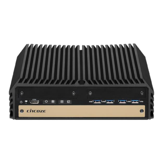
Page 13: Product Pictures
DS-1100 Series | User’s Manual Rugged Embedded Computer 1.3 Product Pictures Rear Front DS-1100 DS-1101 DS-1102 1.4 Key Features • Supports Intel® 6th-Gen Core™ i3 / i5 / i7 Socket-type CPU (LGA1151) • 2x DDR4 SO-DIMM Socket, 2,133MHz, Supports Up to 32 GB •... -
Page 14: Hardware Specification
DS-1100 Series | User’s Manual Rugged Embedded Computer 1.5 Hardware Specification System Expansion Processor • 1x CFM Interface • Intel® Core™ i7-6700TE Processor • 2x CMI Interfaces (8M Cache, up to 3.40 GHz, 35W TDP) • Intel® Core™ i5-6500TE Processor •... -
Page 15: System I/O
DS-1100 Series | User’s Manual Rugged Embedded Computer 1.6 System I/O 1.3.1 Front ATX power on/off switch Ethernet LED Press to power-on or power-off the system Indicates the status of the LAN ports AT/ATX Mode Select Switch USB 3.0 Port Used to select AT or ATX power mode Used to connect USB 3.0/2.0/1.1 device... -
Page 16: Rear
DS-1100 Series | User’s Manual Rugged Embedded Computer DS-1102 1.3.2 Rear DC IN Terminal Block Antenna Hole Used to plug a DC power input with terminal Used to install an antenna jack block COM Port External Fan Terminal Block COM 1 ~ COM 2 support RS232/422/485... - Page 17 DS-1100 Series | User’s Manual Rugged Embedded Computer DS-1100 DS-1101 DS-1102...
-
Page 18: Mechanical Dimension
DS-1100 Series | User’s Manual Rugged Embedded Computer 1.7 Mechanical Dimension DS-1100 Unit: mm DS-1101 Unit: mm... - Page 19 DS-1100 Series | User’s Manual Rugged Embedded Computer DS-1102 Unit: mm...
-
Page 20: Chapter 2 Pin Definitions And Settings
Chapter 2 Pin Definitions and Settings... -
Page 21: Jumper Settings
DS-1100 Series | User’s Manual Rugged Embedded Computer 2.1 Settings When setting the jumpers, ensure that the jumper caps are placed on the correct pins. When the jumper cap is placed on both pins, the jumper is short. If you remove the jumper cap, or place the jumper cap on just one pin, the jumper is open. -
Page 22: Location Of Jumpers, Switches And Connectors
DS-1100 Series | User’s Manual Rugged Embedded Computer 2.2 Location of the Connectors, Jumpers and Switches 2.2.1 Top View... -
Page 23: Bottom View
DS-1100 Series | User’s Manual Rugged Embedded Computer 2.2.2 Bottom View... -
Page 24: List Of Jumpers, Connectors And Switches
DS-1100 Series | User’s Manual Rugged Embedded Computer 2.3 Connector / Jumper / Switch Definition List of Connector / Jumper / Switch Connector Location Definition RTC/SATA DOM/COM1/COM2 Power Select RTC Battery board to board connector AT_ATX1 AT/ATX Power Mode Switch... -
Page 25: Definition Of Switches
DS-1100 Series | User’s Manual Rugged Embedded Computer 2.4 Definition of Switches AT_ATX1: AT / ATX Power Mode Switch Definition 1-2 (Left) AT Power Mode 2-3 (Right) ATX Power Mode (Default) SW1 Pin Defined: RTC / SATA DOM / COM1 / COM2 Power Select... -
Page 26: Definition Of Connectors
DS-1100 Series | User’s Manual Rugged Embedded Computer 2.5 Definition of Connectors CN8: Mini PCI-Express Socket (Support mSATA and SIM Card to Link feature) Definition Definition Definition WAKE# RESERVED 3.3V 3.3V USB_D+ RESERVED PERST# PERN/SATARP 3.3V 1.5V +3.3VAUX CLKREQ# PERP/SATARN... - Page 27 DS-1100 Series | User’s Manual Rugged Embedded Computer CN4/CN5: Mini PCI-Express Socket (Support mSATA feature) Definition Definition Definition WAKE# 3.3V 3.3V USB_D+ 3.3V PERST# PERN/SATARP 3.3V 1.5V +3.3VAUX PERP/SATARN +1.5V REFCLK- SMB_CLK +1.5V REFCLK+ PETN/SATATN SMB_DATA PETP/SATATP +3.3V USB_D- SATA5: SATA Connector(SATA DOM)
- Page 28 DS-1100 Series | User’s Manual Rugged Embedded Computer CLR_CMOS1: Clear BIOS Switch Definition 1-2 (Left) Normal Status (Default) 2-3 (Right) Clear BIOS LED PH1: PWR_LED1 LED Status LED PH1 Power LED LED PH1: TEMP / HDD / GPIO LED Status...
- Page 29 DS-1100 Series | User’s Manual Rugged Embedded Computer DC_IN1: DC Power Input Connector (+9~48V) Connector Type: Terminal Block 1X3 3-pin, 5.0mm pitch Definition +9~48VIN Ignition (IGN) FAN1: External PWM Fan Connector CN6:Remote Power On/Off, Reset Switch Connector Type: Terminal Block 1X3 3-pin, Definition 3.5mm pitch...
- Page 30 DS-1100 Series | User’s Manual Rugged Embedded Computer Optional Low Speed CMI Module (CMI-CD100) Model No. Description CMI Module with 4x RS-232/422/485 Serial Ports, 8x Optical Isolated DIO CMI-CD100/FB20 (4 in/4 out), 1x DS-1100 Front Bezel CMI Module with 4x RS-232/422/485 Serial Ports, 8x Optical Isolated DIO...
- Page 31 DS-1100 Series | User’s Manual Rugged Embedded Computer COM56_SEL1: COM5 / COM6 with Power Select Connector Type: 2X5 10-pin Header, 2.54mm pitch COM5 COM6 Definition Definition 1-3 On 2-4 On 3-5 On +12V 4-6 On +12V 7-9 On 8-10 On...
- Page 32 DS-1100 Series | User’s Manual Rugged Embedded Computer DIO1: Digital Input / Output Connector Connector Type: Terminal Block 2X5 10-pin, 3.5mm pitch Definition Definition DC INPUT Optional Low Speed CMI Module (CMI-ICD100) Model No. Description CMI Module with 4x Electrical Isolated RS-232/422/485 Serial Ports, 8x...
- Page 33 DS-1100 Series | User’s Manual Rugged Embedded Computer DTB-COM: RS232 / RS422 / RS485 Connector Connector Type: 9-pin D-Sub COM3/COM4/COM5/COM6 RS422 / 485 RS485 RS232 Full Duplex Half Duplex Definition Definition Definition DATA- DATA+ Isolated GND Note: COM3/4/5/6 are isolated COM, each pin5 (GND) is independent.
- Page 34 DS-1100 Series | User’s Manual Rugged Embedded Computer Optional CFM-IGN Power Ignition Module Model No. Description CFM Module with Power Ignition Sensing Control Function, 12V/24V Selectable CFM-IGN101 (43 x 36 mm) Power Ignition Setting Connector Location Definition Ignition Function Setting...
-
Page 35: Chapter 3 System Setup
Chapter 3 System Setup... -
Page 36: Disassembling The System For Installation
DS-1100 Series | User’s Manual Rugged Embedded Computer 3.1 Disassembling the System for Installation In order to prevent electric shock or system damage, before removing the chassis cover, must turn off power and disconnect the unit from power source. 1. Turn over the unit to have the bottom side face up, unscrew the 6 screws of bottom cover and place them aside for later use. - Page 37 DS-1100 Series | User’s Manual Rugged Embedded Computer 3. Unscrew the 2 screws at rear panel as marked on photo and place them aside for later use. 4. Loosen the 4 screws. Pull out 4 latches as marked on photo.
- Page 38 DS-1100 Series | User’s Manual Rugged Embedded Computer 5. Lift up the unit vertically by holding the front and rear panel. 6. Turn over the body of the unit and place it gently.
-
Page 39: Installing The Cpu
DS-1100 Series | User’s Manual Rugged Embedded Computer 3.2 Installing the CPU 1. Locate the CPU socket , remove the protection cover on it. 2. Press the CPU socket lever and pull it aside away from the socket to unlock it. Pull back the... - Page 40 DS-1100 Series | User’s Manual Rugged Embedded Computer 3. Align the notches on CPU with the alignment post on socket. 4. The notches of socket provide the space for fingers while lowering the CPU, hold the CPU by the edges toward the notches and insert the CPU gently.
- Page 41 DS-1100 Series | User’s Manual Rugged Embedded Computer 5. Place the thermal pad on the CPU heat spreader. Press down the socket lever to lock the CPU. Thermal pad 6. Align mounting holes of heat sink with the nut studs and fasten the heat sink with provided 4...
-
Page 42: Installing A Mini-Pcie/Msata Card On Top Side
DS-1100 Series | User’s Manual Rugged Embedded Computer 7. Place thermal pad on the top of CPU heatsink in order to provide a seamless contact with the body of chassis to create a efficient heat dissipation. 3.3 Installing a Mini-PCIe/mSATA Card on Top Side (Applicable for full or half size card) 1. - Page 43 DS-1100 Series | User’s Manual Rugged Embedded Computer 2. Use provided two screws fasten the half size module and adapter bracket together as shown in Fig (a) below. (a) Half Size Mini-PCIe Card (b) Full Size Mini-PCIe Card 3. Tilt the Mini PCIe module at a 45 degree angle and insert it to the slot until the gold-pated connector of module contacted firmly with the slot.
-
Page 44: Installing Antennas
DS-1100 Series | User’s Manual Rugged Embedded Computer 3.4 Installing Antennas Please installing a Mini PCIe Wireless Lan Card on top side before you put on washer and fasten the nut with antenna jack. 1. Remove the antenna hole covers at rear panel. - Page 45 DS-1100 Series | User’s Manual Rugged Embedded Computer 4. Assemble the antenna and antenna jack together. 5. Attach the RF connector at another end of cable onto the module.
-
Page 46: Installing A Sata Hard Drive On Top Side
DS-1100 Series | User’s Manual Rugged Embedded Computer 3.5 Installing a SATA Hard Drive on Top Side 1. Unscrew the 3 screws on HDD bracket and remove the bracket. 2. Make the PCB side of the HDD face up, place the HDD bracket on it. Ensure the direction of bracket is correct and use 4 provided screws to assemble HDD and HDD bracket together. - Page 47 DS-1100 Series | User’s Manual Rugged Embedded Computer 3. Turn over the HDD bracket. Connect the HDD bracket to the SATA connector and fasten the 3 screws .
-
Page 48: Installing A Low Speed Cmi Module
DS-1100 Series | User’s Manual Rugged Embedded Computer 3.6 Installing a Low Speed CMI Module The applicable low speed CMI modules for DS1100 series are listed in the following table. Model No. Description CMI Module with 4x RS-232/422/485 Serial Ports, 8x Optical Isolated DIO... - Page 49 DS-1100 Series | User’s Manual Rugged Embedded Computer 2. Locate the connector of CMI-module on top side of system. 3. Insert the CMI module carefully into the CMI connector on main board. Fix it with 4 screws. 4. Fasten the 8 D-Sub jack screws as marked on photo.
- Page 50 DS-1100 Series | User’s Manual Rugged Embedded Computer 5. Exchange with the front bezel of low speed CMI module as illustrated. front bezel for CMI-COM module 6. Fasten the 2 hex nuts from the back side of front bezel.
-
Page 51: Installing A High Speed Cmi Module
DS-1100 Series | User’s Manual Rugged Embedded Computer 3.8 Installing a High Speed CMI Module The applicable high speed CMI modules for DS1100 series are listed in the following table. Model No. Description CMI Module with 4x Intel GbE LAN, RJ45 Port, 1x Universal Bracket... - Page 52 DS-1100 Series | User’s Manual Rugged Embedded Computer 3. Remove the 4 ring nuts from M12 jack before attempting to install the module. 4. (1) Penetrate M12 jack of the module through the I/O hole. (2) Insert the LAN module...
- Page 53 DS-1100 Series | User’s Manual Rugged Embedded Computer 5. Fasten 3 screws to fix the module. 6. Attach the M12 I/O bracket, and fasten 2 hex nuts from the back side of the bracket. M12 I/O bracket...
- Page 54 DS-1100 Series | User’s Manual Rugged Embedded Computer 7.Fasten the 4 ring nuts onto M12 jacks.
-
Page 55: Installing A Mini-Pcie/Msata Card At Bottom Side
DS-1100 Series | User’s Manual Rugged Embedded Computer 3.8 Installing a Mini-PCIe /mSATA Card at Bottom Side (Applicable for full or half size card) 1. Turn over the body of the unit. Locate Mini-PCIe (mSATA) slots at the bottom. 2. Tilt the Mini-PCIe module at a 45 degree angle and insert it to the slot until the gold-pated connector of module contacted firmly with the slot. -
Page 56: Installing So-Dimm Memory
DS-1100 Series | User’s Manual Rugged Embedded Computer 3. Press down the module and use previous two screws to fix the module. 3.9 Installing SO-DIMM Memory 1. Locate the SO-DIMM sockets at the bottom side of system. Unscrews the 4 screws and... - Page 57 DS-1100 Series | User’s Manual Rugged Embedded Computer 2. Locate two SO-DIMM sockets at the bottom. 3. Tilt the SO-DIMM module at a 45 degree angle and insert it to SO-DIMM socket until the gold-pated connector of module contacted firmly with the socket.
- Page 58 DS-1100 Series | User’s Manual Rugged Embedded Computer 4. Press the modules down until it’s fixed firmly by the two locking latches on the sides. 5. Put the cover back and fix the cover with 4 screws.
-
Page 59: Installing A Cfm-Ign Power Ignition Module
DS-1100 Series | User’s Manual Rugged Embedded Computer 3.10 Installing a CFM-IGN Power Ignition Module 1. Locate power ignition connector on main board. 2. Insert the power ignition module carefully into the connector on main board. Fasten 2 screws to fix it. -
Page 60: Installing The Internal Fan
DS-1100 Series | User’s Manual Rugged Embedded Computer 3.11 Installing the Internal FAN (For DS-1102 only) 1. Unscrew 6 screws to remove 3 I/O brackets from rear panel. 2. Attach the FAN from back side of rear panel. Fasten 4 screws to fix it. - Page 61 DS-1100 Series | User’s Manual Rugged Embedded Computer 3. Connect the FAN power cable to the power connector on main board.as marked on photo.
-
Page 62: Installing A Pci/Pcie Add-On Card
DS-1100 Series | User’s Manual Rugged Embedded Computer 3.12 Installing a PCI/PCIe Add-on Card (For DS-1101 and DS-1102 only) The applicable riser cards for DS-1100 series are listed in the following table. Model No. Description RC-E16-01 Riser Card 1 x PCIex16... - Page 63 DS-1100 Series | User’s Manual Rugged Embedded Computer 1. Unscrew the 4 screws to remove the extension bracket. 2. Remove the extension bracket from the system.
- Page 64 DS-1100 Series | User’s Manual Rugged Embedded Computer 3. Assemble the riser card with extension bracket together and fasten with the 4 screws. Extension Bracket 4. (1) Loosen the screw to remove I/O bracket. (2) Loosen the 2 screws halfway to allow the...
- Page 65 DS-1100 Series | User’s Manual Rugged Embedded Computer 5. (1) Insert a PCI(e) add-on card to the slot. (2) Fasten the screw to secure it (3) Push the card retainer forward to against the edge of the add-on card. (4) Tighten the screw to fix the card retainer.
-
Page 66: Assembling The System
DS-1100 Series | User’s Manual Rugged Embedded Computer 7. Install the module assembled in step 4 into the riser card slot, and fasten the 4 screws to secure it. 3.13 Assembling the System 1. Make sure the notch on chassis and the front bezel of body are at the same side. - Page 67 DS-1100 Series | User’s Manual Rugged Embedded Computer 2. Lift up the body of unit. Make sure that both front and rear panels are in the chassis groves and assemble the body on to chassis firmly. 3. Push into the 4 latches as indicated and fasten the 4 screws.
- Page 68 DS-1100 Series | User’s Manual Rugged Embedded Computer 4. Fasten the 2 screws at rear panel. 5. Be sure to align the grooves with front and ear panels. Put the cover back on and fasten the 6 screws to fix the cover.
-
Page 69: Installing A Sata Hard Drive At Front Side
DS-1100 Series | User’s Manual Rugged Embedded Computer 3.14 Installing a SATA Hard Drive at Front Side 1. Loosen the screws in order to remove the front expansion plate. 2. Locate the removable HDD bay and loosen the screw. - Page 70 DS-1100 Series | User’s Manual Rugged Embedded Computer 3. Move the rotating arm out and pull the HDD bracket out. 4. Make the PCB side of the HDD face up, place the HDD bracket into it. Ensure the direction of bracket is correct and use 4 provided screws to assemble HDD and HDD bracket...
- Page 71 DS-1100 Series | User’s Manual Rugged Embedded Computer 5. Align the HDD bracket with the entrance of HDD bay. Holding the rotating arm and insert the HDD bracket until the connector of HDD contact the SATA connector firmly. 6. Place the rotating arm back and fasten the screw.
-
Page 72: Installing A Sim Card
DS-1100 Series | User’s Manual Rugged Embedded Computer 3.15 Installing a SIM Card 1. Locate SIM card slot on top of HDD bay. 2. Insert the SIM card according to the icon instruction aside. -
Page 73: Installing The Cmos Battery
DS-1100 Series | User’s Manual Rugged Embedded Computer 3.16 Installing the CMOS Battery 1. Locate the removable CMOS Battery and loosen the screw. 2. Pull out the CMOS battery bracket with assistance of a tweezer. - Page 74 DS-1100 Series | User’s Manual Rugged Embedded Computer 3. Insert a CMOS battery in the battery slot. 4. Insert the battery bracket firmly and fasten the screw.
-
Page 75: Fasten The Cover
DS-1100 Series | User’s Manual Rugged Embedded Computer 3.17 Fasten the Cover 1. Fasten the cover by using the two screws. 3.18 Install an External Fan 1. Prepare an external fan. Loosen the 2 screws halfway on mounting frame before attempting... - Page 76 DS-1100 Series | User’s Manual Rugged Embedded Computer 2. Slide the FAN into the middle groove of chassis as illustrated. Tighten the 2 screws to fix it onto chassis. 3. Move the fan to the center of chassis. Tighten the 2 screws marked on photo to secure it.
- Page 77 DS-1100 Series | User’s Manual Rugged Embedded Computer 4. Connect the FAN cable to external fan power connector at rear panel.
-
Page 78: Wall Mount Brackets
Rugged Embedded Computer 3.22 Wall Mount Brackets DS-1100 series offers wall mount that customers can install system on the wall in convenient and economical ways. 1. The mounting holes are at the bottom of system. Use provided 8 screws to fasten the... - Page 79 DS-1100 Series | User’s Manual Rugged Embedded Computer 2. Fasten the screws through the bracket mounting hole to mount system on the wall.
-
Page 80: Chapter 4 Bios Setup
Chapter 4 BIOS Setup... -
Page 81: Bios Introduction
DS-1100 Series | User’s Manual Rugged Embedded Computer 4.1 BIOS Introduction The BIOS (Basic Input/Output System) is a program located on a Flash Memory on the motherboard. When you start the computer, the BIOS program will gain control. The BIOS first... -
Page 82: Main Setup
DS-1100 Series | User’s Manual Rugged Embedded Computer 4.2 Main Setup Press <Del> to enter BIOS CMOS Setup Utility, the Main Menu (as shown below) will appears on the screen. Use arrow keys to move among the items and press <Enter> to accept or enter a sub-menu. -
Page 83: Advanced Setup
DS-1100 Series | User’s Manual Rugged Embedded Computer 4.3 Advanced Setup This section allows you to configure and improve your system and allows you to set up some system features according to your preference. 4.3.1 ACPI Settings... -
Page 84: Amt Configuration
DS-1100 Series | User’s Manual Rugged Embedded Computer ■ Enable ACPI Auto Configuration [Disabled] Enables or disables BIOS Advanced Configuration Power Interface® (ACPI) auto configuration. ■ Enable Hibernation [Enabled] Enables or disables system ability to hibernate state (OS/S4 state). This option may not be effective with some OS. -
Page 85: Pch-Fw Configuration
DS-1100 Series | User’s Manual Rugged Embedded Computer ■ Un-Configure ME [Disabled] Enables or disables Un-Configure-Management Engine(ME) without password. 4.3.3 PCH-FW Configuration ■ Firmware Update Configuration Configure Management Engine Parameters Me FW Image Re-Flash [Disabled] Enables or disables Me FW Image Re-Flash function. -
Page 86: F81866 Super Io Configuration
DS-1100 Series | User’s Manual Rugged Embedded Computer 4.3.4 F81866 Super IO Configuration Set Parameters of Serial Ports. User can Enable/Disable the serial port and Select an optimal settings for the Super IO Device ■ Serial Port 1~6 Configuration. -
Page 87: Hardware Monitor
DS-1100 Series | User’s Manual Rugged Embedded Computer Serial Port [Enabled] Enables or disables serial port. Change Settings [Auto] Allows users to change the address & IRQ settings of the specified serial port. Onboard Serial Port 1~6 Mode [RS232] Allows users to select Serial Port Mode. -
Page 88: S5 Rtc Wake Settings
DS-1100 Series | User’s Manual Rugged Embedded Computer PC Health Status ■ PWM Fan Function [Disabled] Enables or disables PWM Fan function. ■ PWM Fan Mode Configuration PWM Fan1 Duty [60%] This item allows users to change duty cycle value of PWM Fan1. -
Page 89: Serial Port Console Redirection
DS-1100 Series | User’s Manual Rugged Embedded Computer 4.3.7 Serial Port Console Redirection ■ Console Redirection [Disabled] These items allow users to enable or disable COM0, COM1, COM2, COM3, COM4, COM5 console redirection function. 4.3.8 CPU Configuration... -
Page 90: Sata Configuration
DS-1100 Series | User’s Manual Rugged Embedded Computer ■ Active Process Cores [All] Allows you to choose the number of active processor cores. Configuration options: [All] [1]. ■ Intel® Virtualization Technology [Enabled] Enables or disables Intel® Virtualization Technology, which will allow a platform to run multiple operating systems and applications in independent partitions. - Page 91 DS-1100 Series | User’s Manual Rugged Embedded Computer ■ Software Feature Mask Configuration RAID option ROM (OROM) / Intel® Rapid Storage Technology(RST) driver will refer to the software feature configuration to enable or disable the storage features. ■ Software Feature Mask Configuration RAID option ROM (OROM) / Intel®...
-
Page 92: Pci Subsystem Settings
DS-1100 Series | User’s Manual Rugged Embedded Computer ■ Serial ATA Port 0 Port 0 [Enabled] Enables or disables SATA Port 0. ■ Serial ATA Port 1 Port 1 [Enabled] Enables or disables SATA Port 1. Hot Plug [Disabled] Enables or disables Hot Plug support for port1. - Page 93 DS-1100 Series | User’s Manual Rugged Embedded Computer ■ PCI Latency Timer [32 PCI Bus Clocks] Allows you to set the value to be programed into PCI latency Timer Register. Configuration options: [32][64][96][128][160][192][224][248] PCI Bus Clocks. ■ PCI-X Latency Timer [64 PCI Bus Clocks] Allows you to set the value to be programed into PCI latency Timer Register.
-
Page 94: Csm Configuration
DS-1100 Series | User’s Manual Rugged Embedded Computer ■ BIOS Hot-Plug Support [Disabled] Enables or disables BIOS build in Hot-Plug support. Use this feature if OS does not support PCI Express and SHPC hot-plug natively. ■ PCI Buses Padding [1] Allows users to set PCI Buses Padding. - Page 95 DS-1100 Series | User’s Manual Rugged Embedded Computer Compatibility Support Module Configuration This option controls legacy/UEFI ROMs priority ■ Boot option filter [Legacy only] Allows you to select which type of operating system to boot. [UEFI and Legacy]: Allows booting from operating systems that support legacy option ROM or UEFI option ROM.
-
Page 96: Usb Configuration
DS-1100 Series | User’s Manual Rugged Embedded Computer 4.3.12 USB Configuration ■ Legacy USB Support [Enabled] This item allows users to enable or disable legacy USB support. When set to [Auto], legacy USB support will be disabled automatically if no USB devices are connected. -
Page 97: Chipset Setup
DS-1100 Series | User’s Manual Rugged Embedded Computer 4.4 Chipset Setup This section allows you to configure chipset related settings according to user’s preference. 4.4.1 System Agent (SA) Configuration... -
Page 98: Pch-Io Configuration
DS-1100 Series | User’s Manual Rugged Embedded Computer ■ VT-d [Enabled] Enables or disables Intel® Virtualization Technology for Directed I/O (VT-d) capability. ■ Above 4GB MMIO BIOS assignment [Disabled] Enables or disables Above 4GB Memory Mapped IO BIOS assignment. This is disabled automatically when Aperture Size is set to 2048MB. - Page 99 DS-1100 Series | User’s Manual Rugged Embedded Computer ■ PCI Express Configuration PCI Express x1 Slot PCI Express Root Port 1 [Enabled] Enables or disables PCI Express Root Port 1. PCIeSpeed [Auto] Allows you to select PCI Express port speed.
- Page 100 DS-1100 Series | User’s Manual Rugged Embedded Computer ■ LAN i219LM Controller [Enabled] Enables or disables i219LM LAN Controller. ■ LAN i210AT Controller [Enabled] Enables or disables i210AT LAN Controller. ■ Wake on LAN [Enabled] Enables or disables integrated LAN Wake On LAN function.
-
Page 101: Security Setup
DS-1100 Series | User’s Manual Rugged Embedded Computer 4.5 Security Setup This section allows users to configure BIOS security settings. 4.5.1 Administrator Password Allows you to set Administrator Password to control access to the BIOS Setup utility. 4.5.2 User Password Allows you to set User Password to control access to the system at boot and to the BIOS Setup utility. -
Page 102: Boot Setup
DS-1100 Series | User’s Manual Rugged Embedded Computer 4.6 Boot Setup This section allows you to configure Boot settings. 4.6.1 Setup Prompt Timeout [1] Use this item to set number of seconds (1..65535) to wait for setup activation key. 4.6.2 Bootup NumLock State [On] Allows you to set NumLock key to <On>... -
Page 103: Save & Exit
DS-1100 Series | User’s Manual Rugged Embedded Computer 4.7 Save & Exit 4.7.1 Save Changes and Exit This item allows you to exit system setup after saving changes. 4.7.2 Discard Changes and Exit This item allows you to exit system setup without saving changes. -
Page 104: Chapter 5 Product Application
Chapter 5 Product Application (For CMI-CD, CMI-ICD only) -
Page 105: Digital I/O (Dio) Application
DS-1100 Series | User’s Manual Rugged Embedded Computer This chapter descripts the DIO applications for CMI-CD, CMI-ICD only. 5.1 Digital I/O (DIO) Application This section describes DIO application of the product. The content and application development are better understood and implemented by well experienced professionals or developers. - Page 106 DS-1100 Series | User’s Manual Rugged Embedded Computer 5.1.1.3 Relative Registers To program the F81866A configuration registers, the following configuration procedures.
- Page 107 DS-1100 Series | User’s Manual Rugged Embedded Computer 5.1.1.4 Sample Code in C Language 5.1.1.4.1 Control of GP74 to GP77 (DI1 ~ DI4) #define AddrPort 0x4E #define DataPort 0x4F <Enter the Extended Function Mode> WriteByte(AddrPort, 0x87) WriteByte(AddrPort, 0x87) //Must write twice to entering Extended mode <Select Logic Device>...
- Page 108 // Select configuration register 60h (High Byte address) WriteByte(DataPort, ( 0x0A)) WriteByte(AddrPort, 0x61) // Select configuration register 61h (Low Byte address) WriteByte(DataPort, ( 0x00)) <Leave the Extended Function Mode> WriteByte(AddrPort, 0xAA) Cincoze default DIO Port base address is set to 0x0A00h...
- Page 109 DS-1100 Series | User’s Manual Rugged Embedded Computer 5.1.1.6 DATA Bit Table (DIO) 7 6 5 4 3 2 1 0 = DI1 0 0 0 1 - - - - value (Base address +3) (0xA03) 7 6 5 4 3 2 1 0...
-
Page 110: Cmi-Cd, Cmi-Icd Digital I/O (Dio) Hardware Specification
DS-1100 Series | User’s Manual Rugged Embedded Computer 5.1.1.7 DIO I/O Port Address (Default Address 0xA00) Pin Definition Data Bits 0xA03 0xA02 I/O Port address 5.2 CMI-CD, CMI-ICD Digital I/O (DIO) Hardware Specification • 4x Digital Input (Source Type) • Input Voltage (Dry Contact) -
Page 111: Cmi-Cd, Cmi-Icd Connector Definitions
DS-1100 Series | User’s Manual Rugged Embedded Computer 5.2.1 CMI-CD, CMI-ICD Connector Definition DIO1: Digital Input / Output Connector Connector Type: Terminal Block 2X5 10-pin, 3.5mm pitch Definition Definition DC INPUT... - Page 112 © 2014 Cincoze Co., Ltd. All rights reserved. The Cincoze logo is a registered trademark of Cincoze Co., Ltd. All other logos appearing in this catalog are the intellectual property of the respective company, product, or organization associated with the logo.
Need help?
Do you have a question about the DS-1100 Series and is the answer not in the manual?
Questions and answers