
Related Manuals for Cincoze DI-1100 Series


Summary of Contents for Cincoze DI-1100 Series
- Page 1 DI-1100 Series User Manual Rugged Embedded Computer Compact, High Performance, Modular Embedded Computer with 8th Gen Intel® Core™ U CPU (Whiskey Lake) Version: V1.00...
-
Page 2: Table Of Contents
3.8 Installing SIM Card ......................42 3.9 Installing Wall Mount ......................43 3.10 VESA Mount ........................45 3.11 Connecting to Power Supply ................... 46 Chapter 4 BIOS Setup ......................47 4.1 BIOS Introduction ......................48 DI-1100 Series | User Manual... - Page 3 Chapter 5 Product Application ..................66 5.1 Digital I/O (DIO) application ....................67 5.1.1 Digital I/O Programming Guide ................67 5.2 DIO Hardware Specification ....................76 5.2.1 DIO Connector Definition ..................77 Chapter 6 Optional Modules & Accessories ............... 79 DI-1100 Series | User Manual...
- Page 4 6.5.3 MEC-COM-M212-TDB9/UB1503-R10 Module ............107 6.6 Installing External FAN ....................110 6.6.1 FAN-EX103 ......................110 6.7 Installing DIN-Rail Mount Kit................... 112 6.7.1 DINRAIL-R10 ......................112 6.8 Installing Side Mount Kit ....................113 6.8.1 SIDE01 ......................... 113 DI-1100 Series | User Manual...
-
Page 5: Preface
2021/11/15 Copyright Notice © 2021 by Cincoze Co., Ltd. All rights are reserved. No parts of this manual may be copied, modified, or reproduced in any form or by any means for commercial use without the prior written permission of Cincoze Co., Ltd. -
Page 6: Product Warranty Statement
Product Warranty Statement Warranty Cincoze products are warranted by Cincoze Co., Ltd. to be free from defect in materials and workmanship for 2 years from the date of purchase by the original purchaser. During the warranty period, we shall, at our option, either repair or replace any product that proves to be defective under normal operation. - Page 7 Before sending your product in, you will need to fill in Cincoze RMA Request Form and obtain an RMA number from us. Our staff is available at any time to provide you with the most friendly and immediate service. ◼...
-
Page 8: Technical Support And Assistance
Technical Support and Assistance 1. Visit the Cincoze website at www.cincoze.com where you can find the latest information about the product. 2. Contact your distributor or our technical support team or sales representative for technical support if you need additional assistance. Please have following information ready before you call: ⚫... -
Page 9: Safety Precautions
The equipment has obvious signs of breakage. 14. CAUTION: Danger of explosion if battery is incorrectly replaced. Replace only with the same or equivalent type recommended by the manufacturer. 15. Equipment intended only for use in a RESTRICTED ACCESS AREA. DI-1100 Series | User Manual... -
Page 10: Ordering Information
DI-1100 Embedded System x1 Heatsink Pack x1 Utility DVD Driver x1 Screw Pack x1 Wall Mount Kit x1 Power Terminal Block Connector x1 Remote Function Terminal Block Connector x 2 Fan Terminal Block Connector x 1 DI-1100 Series | User Manual... -
Page 11: Chapter 1 Product Introductions
Chapter 1 Product Introductions DI-1100 Series | User Manual... -
Page 12: Overview
I/Os and other expansion options into a very compact chassis, making it the perfect high-performance rugged embedded computer for space-constrained environments. The DI-1100 is ideal for industrial applications, logistics and warehousing, transportation, security and surveillance, IoT deployments, and other applications. 1.2 Highlights DI-1100 Series | User Manual... - Page 13 DI-1100 Series | User Manual...
-
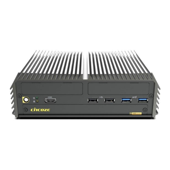
Page 14: Product Pictures
Optional CMI modules (2x 10 GbE LAN, M12 A-coded, or M12 X-coded) ⚫ Optional CFM modules (power ignition sensing, or 4x PoE) ⚫ Wide operating temperature -40°C to 70°C ⚫ MIL-STD-810G, E-mark and EN50155 (EN 50121-3-2 only) certified DI-1100 Series | User Manual... -
Page 15: Hardware Specification
• 2x 5 Gbps USB 3.2 Gen1, Type A • 2x 480 Mbps USB 2.0, Type A • 1x PS/2, 6 Pin Mini-DIN Female Connector PS/2 Storage • 1x 2.5” Front Accessible SATA HDD/SSD Bay (SATA 3.0) SSD/HDD DI-1100 Series | User Manual... - Page 16 Physical • 203 x 142 x 66.8 mm Dimension (W x D x H) • 1.74 KG Weight Information • Extruded Aluminum with Heavy Duty Metal Mechanical Construction • Wall/ Side/ DIN-RAIL/ VESA Mount Mounting DI-1100 Series | User Manual...
- Page 17 • CE, FCC, ICES-003 Class A, EN50121-3-2 (Railway), E-mark • IEC/EN 62368-1 Safety * Product Specifications and features are for reference only and are subject to change without prior notice. For more information, please refer to the latest product datasheet from Cincoze's website. DI-1100 Series | User Manual...
-
Page 18: System I/O
A switch used to clear CMOS to reset BIOS USB 3.2 Gen2 Reset Used to connect USB 3.2 Gen2/3.2 Gen1/2.0 A button used to reset the system device Universal I/O Bracket Used for customized I/O output DI-1100 Series | User Manual... - Page 19 A terminal block used to connect to remote LAN1, LAN2 power on/off LED Remote Power On/Off Used to connect to local area network PS/2 A terminal block used to connect to remote Used to connect the PS/2 device power on/off switch DI-1100 Series | User Manual...
-
Page 20: Mechanical Dimension
1.7 Mechanical Dimension Unit: mm DI-1100 Series | User Manual... -
Page 21: Chapter 2 Switches & Connectors
Chapter 2 Switches & Connectors DI-1100 Series | User Manual... -
Page 22: Location Of Switches And Connectors
2.1 Location of Switches and Connectors 2.1.1 Top View 2.1.2 Bottom View DI-1100 Series | User Manual... -
Page 23: Switches And Connectors List
DDR4 SO-DIMM connector FS_1 DC input power 15A/58V RESET1 Reset button CLR_CMOS1 Clear COMS switch setting AT_ATX1 AT_ATX1 switch setting f, g SIM1, SIM2 SIM Card socket A and B SATA2 22 Pins SATA connector DI-1100 Series | User Manual... -
Page 24: Definition Of Switches And Connectors
LED1 LED Color POWER POWER Green Yellow PWR_SW1: Power button Switch Definition Push Power System MODE_SEL1: Super CAP Function Setting Location Function DIP1 DIP2 Super CAP ON (Default) Enabled ON (Default) MODE_SEL1 Super CAP Disabled DI-1100 Series | User Manual... - Page 25 LAN LED Status Definition Link LED Status Definition Steady Green 1 Gbps Network Link Steady Orange 100 Mbps Network Link 10 Mbps Network Link Act LED Status Definition Blinking Yellow Data Activity Steady Yellow No Activity DI-1100 Series | User Manual...
- Page 26 3.3V PERST# PERN0/SATARP0 3.3V 1.5V 3.3V CLKREQ# PERP0/SATARN0 RESERVED 10 NA +1.5V 11 REFCLK- 12 NA SMB_CLK +1.5V 13 REFCLK+ PETN0/SATATN0 14 NA SMB_DATA 15 GND PETP0/SATATP0 16 NA +3.3V 17 NA 18 GND USB_D- DI-1100 Series | User Manual...
- Page 27 3.3V PERST# PERN1/SATARP1 3.3V 1.5V 3.3V CLKREQ# PERP1/SATARN1 SIM_PWR 10 SIM_DATA +1.5V 11 REFCLK- 12 SIM_CLK SMB_CLK +1.5V 13 REFCLK+ PETN1/SATATN1 14 SIM_RESET SMB_DATA 15 GND PETP1/SATATP1 16 SIM_VPP +3.3V 17 NA 18 GND USB_D- DI-1100 Series | User Manual...
- Page 28 CN1:Remote power button/ LED Connector Remote Power LED connector can connect an external LED indicator up to 10mA. Connector Type: Terminal Block 2X2 4-pin, 3.5mm pitch Definition PWR_SW RMT_PWR_LED_A Do not apply power to this connector! DI-1100 Series | User Manual...
- Page 29 DC_IN1: 3 PINs DC 9‐48V power input with power ignition connector Connector Type: Terminal Block 1x3 3-pin, 5.0mm pitch Definition +9~48VIN Ignition (IGN) 1 2 3 Please disconnect the power source before mounting the DC power cables or connecting the DC power connector to system. DI-1100 Series | User Manual...
-
Page 30: Chapter 3 System Setup
Chapter 3 System Setup DI-1100 Series | User Manual... -
Page 31: Removing Top Cover
1. Turn over the unit to have the bottom side face up, loosen the 6 screws on the bottom cover and place them aside for later use. 2. Remove the bottom cover from the chassis. DI-1100 Series | User Manual... - Page 32 3. Lift up the unit vertically by holding the front and rear panel. 4. Turn over the body of the unit and place it gently. DI-1100 Series | User Manual...
-
Page 33: Installing So-Dimm
1. Locate the SO-DIMM socket on the top side of system. 2. Insert the SO-DIMM at a 45-degree angle until its edge connector is connected to the SO-DIMM socket firmly. 45° 3. Press down the module until the retaining clips snap back in place. DI-1100 Series | User Manual... -
Page 34: Installing Mini-Pcie Card
Tilt a Mini PCIe card at a 45-degree angle and insert it to the socket until the golden finger connector of the card seated firmly. 45° Press the card down and secure it with 2 screws. DI-1100 Series | User Manual... -
Page 35: Installing Antenna
Installing an antenna jack with a diameter greater than 9 mm on the right side of the system will collide with the terminal connector below. In this case, please try to install the antenna on the left side of the system. DI-1100 Series | User Manual... - Page 36 4. Assemble the antenna and antenna jack together. 5. Attach the RF connector of the cable’s another end onto the card. DI-1100 Series | User Manual...
-
Page 37: Installing The Thermal Pad
2. Remove the protective film on the thermal pad. Protective Film 3. Paste the thermal pad onto the heatsink carefully. Thermal pad Before assembling the system’s chassis cover, please make sure the transparent protective film on the Thermal Pad has been removed! DI-1100 Series | User Manual... -
Page 38: Assembling Top Cover
1. Make sure the notch on the chassis and the front bezel of the unit body are on the same side. 2. Lift the body of the unit, make sure that the front and rear panels are in the chassis groves, and then assemble the body into the chassis. DI-1100 Series | User Manual... - Page 39 3. Place the bottom cover back to system. 4. Fasten the 6 screws to fix the cover. DI-1100 Series | User Manual...
-
Page 40: Installing Sata Hard Drives At Front Panel
3. Pull the rotating arm and pull the HDD bracket out of system. 4. Make HDD bottom side face up, place the HDD bracket on it. Ensure the direction of bracket is correct and use 4 provided screws to assemble HDD and HDD bracket together. DI-1100 Series | User Manual... - Page 41 5. Align the HDD bracket with the entrance of HDD bay. Insert the HDD bracket and push it until the HDD connector is fully inserted into the SATA slot. 6. Place the rotating arm back and fasten the screw. 7. Fix the cover plate of maintenance zone by fastening the two screws. DI-1100 Series | User Manual...
-
Page 42: Installing Sim Card
2. Locate the SIM card slot at front side and insert a SIM card into a SIM slot with the gold contacts facing up. Please pay attention to the insert orientation as illustrated. 3. Fix the cover plate of maintenance zone by fastening the two screws. DI-1100 Series | User Manual... -
Page 43: Installing Wall Mount
3.9 Installing Wall Mount DI-1100 series offers wall mount that customers can install system on the wall in a convenient and economical way. 1. The mounting holes are at the bottom side of system. Use provided 4 screws to fasten the bracket on each side. - Page 44 2. There are 2 bracket mounting holes at left and right side for customer fix the system on the wall. DI-1100 Series | User Manual...
-
Page 45: Vesa Mount
VESA 75mm and 100 mm standard for various usage. The following picture illustrates the installation of DI-1100 series on a VESA stand. Align the 4 screw holes of VESA stand with the screw holes on bottom side of system. Fasten 4 screws to fix it. -
Page 46: Connecting To Power Supply
Then connect the phoenix contacts of the power supply to the DC_IN1 connector. 3. Fasten the two screws to fix the phoenix contacts. In formal use, please use new Phoenix contacts and make sure the screws are tightened to avoid poor connection. DI-1100 Series | User Manual... -
Page 47: Chapter 4 Bios Setup
Chapter 4 BIOS Setup DI-1100 Series | User Manual... -
Page 48: Bios Introduction
You can use arrow keys ( ↑↓ ) to highlight the field and press <Enter> to call up the sub-menu. Then you can use the control keys to enter values and move from field to field within a sub-menu. If you want to return to the main menu, just press the <Esc >. DI-1100 Series | User Manual... -
Page 49: Main Setup
Use arrow keys to move among the items and press <Enter> to accept or enter a sub-menu. 4.2.1 System Date Set the date. Please use <Tab> to switch between date elements. 4.2.2 System Time Set the time. Please use <Tab> to switch between time elements. DI-1100 Series | User Manual... -
Page 50: Advanced Setup
With virtualization, one computer system can function as multiple virtual systems. ■ Active Process Cores [All] Allows users to choose the number of active processor cores. Configuration options: [All] [1] [2] [3] ■ Hyper-threading Enables or disables for Hyper-Threading Technology. DI-1100 Series | User Manual... -
Page 51: Pch-Fw Configuration
Allows users to enable or disable Intel® Active Management Technology BIOS execution. (This function can be opened for customization.) ■ Firmware Update Configuration ❑ ME FW Image Re-Flash [Disabled] Allows users to enable or disable ME firmware image re-flash function. DI-1100 Series | User Manual... -
Page 52: Trusted Computing
Allows users to select the highest Advanced Configuration Power Interface® (ACPI) sleep state that system will enter when suspend button is pressed. [Suspend Disabled]: Disables entering suspend state. [S3 (suspend to RAM)]: Enables suspend to RAM state. DI-1100 Series | User Manual... -
Page 53: F81866 Super Io Configuration
This item allows users to change the address & IRQ settings of the specified serial port. ❑ Onboard Serial Port 1 Mode [RS232] This item allows users to select Serial Port Mode. Configuration options: [RS232] [RS422/RS485 Full Duplex] [RS485 Half Duplex] DI-1100 Series | User Manual... -
Page 54: Hardware Monitor
These items display the current status of all monitored hardware devices/ components such as voltages and temperatures. ■ External Smart Fan Function [Enabled] Enables or disables external smart fan function. ■ External Smart Fan Configuration Allows users to setting external smart fan parameters. DI-1100 Series | User Manual... -
Page 55: S5 Rtc Wake Settings
[Fixed Time]: Set the specified time (HH:MM:SS) to wake system. [Dynamic Time]: Set the increase time from current time to wake system. 4.3.8 Serial Port Console Redirection ■ Console Redirection [Disabled] These items allow users to enable or disable COM1, COM2 console redirection function. DI-1100 Series | User Manual... -
Page 56: Usb Configuration
This item allows users to enable or disable XHCI (USB3.2) hand-off function. ■ USB Mass Storage Driver Support [Enabled] Enables or disables support for USB mass storage devices. 4.3.10 CSM Configuration ■ CSM Support [Disabled] Enables or disables compatibility support module. DI-1100 Series | User Manual... -
Page 57: Network Stack Configuration
4.3.11 Network Stack Configuration ■ Network Stack [Disabled] Enables or disables UEFI Network Stack. DI-1100 Series | User Manual... -
Page 58: Chipset Setup
4.4 Chipset Setup This section allows you to configure chipset related settings according to user’s preference. 4.4.1 System Agent (SA) Configuration DI-1100 Series | User Manual... - Page 59 ■ Memory Configuration This item displays detailed memory information in the system. ■ VT-d [Enabled] This item allows users to enable or disable Intel® Virtualization Technology for Directed I/O (VT-d) function. DI-1100 Series | User Manual...
-
Page 60: Pch-Io Configuration
❑ PCI Express Root Port 6 (MiniPCIe2) ◼ PCI Express Root Port [Enabled] Allows you to enable or disable the PCI Express Port. ◼ PCIe Speed [Auto] Allows you to select PCI Express interface speed. Configuration options: [Auto] [Gen1] [Gen2] [Gen3]. DI-1100 Series | User Manual... - Page 61 This item allows users to choose [AHCI] or [RAID] mode. ❑ Serial ATA Port 0 Port 0 [Enabled] Enables or disables SATA Port 0 (Location: SATA2). ❑ Serial ATA Port 1 Port 1 [Enabled] Enables or disables SATA Port 1 (Location: MINIPCIE1). DI-1100 Series | User Manual...
- Page 62 Allows you to specify which power state system will enter when power is resumed after a power failure (G3 state). [Always on]: Enters to power on state. [Always off]: Enters to power off state. [Keep last state]: Enters to the last power state before a power failure. DI-1100 Series | User Manual...
-
Page 63: Security Setup
User Password controls access to the system at boot and to the BIOS Setup utility. 4.5.3 Security Boot ❑ Secure Boot [Disabled] Enable or disable Secure Boot function. ❑ Secure Boot Mode [Standard] Allows you to select Secure Boor Mode. Configuration options: [Standard] [Custom]. DI-1100 Series | User Manual... -
Page 64: Boot Setup
Allows users to select the power-on state for keyboard NumLock. 4.6.3 Quiet Boot [Disabled] Allows users to enable or disable Quiet Boot function. 4.6.4 Fast Boot [Disabled] Allows users to enable or disable Fast Boot function. DI-1100 Series | User Manual... -
Page 65: Save & Exit
4.7.8 Save as User Defaults This item allows users to save the changes done so far as user defaults. 4.7.9 Restore User Defaults This item allows users to restore the user defaults to all the options. DI-1100 Series | User Manual... -
Page 66: Chapter 5 Product Application
Chapter 5 Product Application DI-1100 Series | User Manual... -
Page 67: Digital I/O (Dio) Application
5.1.1.1 Pins for Digital I/O Item Standard GPIO30 (Pin36) GPIO31 (Pin37) GPIO32 (Pin38) GPIO33 (Pin39) GPIO34 (Pin40) GPIO35 (Pin41) GPIO36 (Pin42) GPIO37 (Pin43) GPIO50 (Pin9) GPIO51 (Pin10) GPIO52 (Pin11) GPIO53 (Pin12) GPIO54 (Pin13) GPIO55 (Pin14) GPIO56 (Pin15) GPIO57 (Pin16) DI-1100 Series | User Manual... - Page 68 Following is an example to enable configuration and to disable configuration by using debug. -o 4e 87 -o 4e 87 (enable configuration) -o 4e aa (disable configuration) 5.1.1.3 Relative Registers To program the F81866A configuration registers, see the following configuration procedures. DI-1100 Series | User Manual...
- Page 69 DI-1100 Series | User Manual...
- Page 70 DI-1100 Series | User Manual...
- Page 71 // Assume read (bit 0~7) to Value is FFh , thus GP30 ~37 are all high. // Assume read (bit 0~7) to Value is 00h , thus GP30 ~37 are all low. // Read Value range: 00h~FFh <Leave the Extended Function Mode> WriteByte(AddrPort, 0xAA) DI-1100 Series | User Manual...
- Page 72 <Output Value> WriteByte(AddrPort, 0xA1) // Select configuration register A1h WriteByte(DataPort, Value) // Set bit 0~7=(0/1) to output GP 50~57 as Low or High // Write Value Range: 0x00 ~0xFF <Leave the Extended Function Mode> WriteByte(AddrPort, 0xAA) DI-1100 Series | User Manual...
- Page 73 // Select configuration register 60h (High Byte address) WriteByte(DataPort, 0x0A) WriteByte(AddrPort, 0x61) // Select configuration register 61h (Low Byte address) WriteByte(DataPort, 0x00) <Leave the Extended Function Mode> WriteByte(AddrPort, 0xAA) Cincoze default GPIO Port base address is 0xA00 DI-1100 Series | User Manual...
- Page 74 = DI6 = DO6 (Base (Base address +9) address +5) (0xA09) (0xA05) = DI7 = DO7 (Base (Base address +9) address +5) (0xA09) (0xA05) = DI8 = DO8 (Base (Base address +9) address +5) (0xA09) (0xA05) DI-1100 Series | User Manual...
- Page 75 5.1.1.7 DIO I/O Port Address (Default Address 0xA00) Pin Definition Data Bits DIO Type Digital Input I/O Port Address 0xA09 Pin Definition Data Bits DIO Type Digital Output I/O Port Address 0xA05 DI-1100 Series | User Manual...
-
Page 76: Dio Hardware Specification
DO Signal have to pull up resistor to XCOM+ for external device, the resistance will affect the pull up current Signal High Level: Pull up resistor to XCOM+ Signal Low Level: = XCOM- Sink Current: 1A (Max) DI-1100 Series | User Manual... -
Page 77: Dio Connector Definition
5.2.1 DIO Connector Definition Pin1 Pin1 Digital Input Digital Output Digital Input/ Output Connector Connector Type: Terminal Block 2X10 20-pin, 3.5mm pitch Location Definition Location Definition DC INPUT DC INPUT (XCOM+) (XCOM+) Digital Input Digital Output (XCOM-) (XCOM-) DI-1100 Series | User Manual... - Page 78 Reference Input Circuit Reference Output Circuit DI-1100 Series | User Manual...
-
Page 79: Chapter 6 Optional Modules & Accessories
Chapter 6 Optional Modules & Accessories DI-1100 Series | User Manual... -
Page 80: Optional Module Pin Definition & Settings
CMI-M12 LAN Module Pin Definitions Connector Type: M12 A-coded 8pin connector Definition Definition 2_LAN1_0+ 2_LAN1_0- 2_LAN1_1+ 2_LAN1_2+ 2_LAN1_2- 2_LAN1_1- 2_LAN1_3+ 2_LAN1_3- 6.1.2 CMI-XM12LAN01-R10/UB1510-R10 Module CMI-XM12LAN01 Module Pin Definitions Connector Type: M12 X-coded 8pin connector Pin Definition Definition DI-1100 Series | User Manual... -
Page 81: Cmi-10Glan04-R10/Ub1528-R10 Module
6.1.3 CMI-10GLAN04-R10/UB1528-R10 Module LAN LED Definition Link LED Status Definition Steady Green 10 Gbps Network Link Steady Orange 1Gbps Network Link 100Mbps Network Link Act LED Status Definition Blinking Green Data Activity Steady Green No Activity DI-1100 Series | User Manual... -
Page 82: Cmi-Com05-R10/Ub1503-R10 Module
DATA + MODE3 on CMI-COM05 Module:COM3 Power Select Location Function DIP1 DIP2 0V(RI) ON (Default) ON (Default) MODE3 COM3 MODE4 on CMI-COM05 Module:COM4 Power Select Location Function DIP3 DIP4 0V(RI) ON (Default) ON (Default) MODE4 COM4 DI-1100 Series | User Manual... -
Page 83: Cfm-Ign102 Module
Default setting of Pin1 to Pin4 is OFF/ OFF/ OFF/ OFF. 24V_12V_1:IGN Module Voltage Mode Setting Switch 12V/ 24V Car Battery Switch Switch Definition Left 12V Car Battery Input Right 24V Car Battery Input (Default) DI-1100 Series | User Manual... -
Page 84: Installing High Speed Cmi Module
1. Loosen the 2 screws and remove the front bezel. 2. Locate the BTB_FH1 connector of the CMI module on the top side of system. 3. Insert the CMI module vertically until it’s connected firmly and fasten 2 screws to fix it. DI-1100 Series | User Manual... -
Page 85: Cmi-M12Lan01-R12/Ub1510-R10 Module
4. Attach the I/O bracket on to the system, and fasten the two screws to fix it. 6.2.2 CMI-M12LAN01-R12/UB1510-R10 Module 1. Loosen the 2 screws and remove the front bezel. 2. Locate the BTB_FH1 connector of the CMI module on the top side of system. DI-1100 Series | User Manual... - Page 86 Remove the four hex rings from the CMI-M12LAN module. 4. Insert the CMI module vertically until it’s connected firmly and fasten 2 screws to fix it. 5. Attach the I/O bracket on to the system, and fasten the two screws to fix it. DI-1100 Series | User Manual...
-
Page 87: Cmi-Xm12Lan01-R10/Ub1510-R10 Module
6. Fasten the four hex rings to fix the cover plate. 6.2.3 CMI-XM12LAN01-R10/UB1510-R10 Module Hex washers M12 I/O bracket Hex rings Rubber rings DI-1100 Series | User Manual... - Page 88 Penetrate hex rings through the M12 I/O bracket holes, and fix them with hex washers. 2. Loosen the 2 screws and remove the front bezel. 3. Locate the BTB_FH1 connector of the CMI module on the top side of system. DI-1100 Series | User Manual...
- Page 89 2 screws to fix it. 5. Attach the assembled M12 I/O bracket on to the system, and fasten the hex nuts to fix it. 6. Put on the rubber rings to the four M12 LAN ports. DI-1100 Series | User Manual...
-
Page 90: Cmi-10Glan04-R10/Ub1528-R10 Module
[BTB_FH4 Mode Selection] setting from default mode [4x1] to mode [1x4]. 1. Loosen the 2 screws and remove the front bezel. 2. Locate the BTB_FH1 connector of the CMI module on the top side of system. DI-1100 Series | User Manual... - Page 91 4. Put on the heatsink and turn over the module. Fasten the 3 screws (M3X5L) to fix the heatsink. Insert the CMI module vertically into the female connector on system’s mainboard until it’s connected firmly and fasten the 2 screws (M3X12L) to fix it. DI-1100 Series | User Manual...
- Page 92 Before assembling the system’s chassis cover, please make sure the transparent protective film on the Thermal Pad has been removed! 7. Attach the I/O bracket on to the system, and fasten the two screws to fix it. DI-1100 Series | User Manual...
-
Page 93: Installing Low Speed Cmi Module
1. Loosen the 2 screws and remove the front bezel. 2. Locate the BTB_FH2 connector of the CMI module on the top side of system. 3. Insert the CMI module vertically until it’s connected firmly and fasten the screw to fix it. DI-1100 Series | User Manual... -
Page 94: Cmi-Com05-R10/Ub1503-R10 Module
After installing CMI-COM05-R10 module, users need to enter BIOS to check the items for CMI-COM05-R10 module, which are “Serial Port 3 Configuration” and “Serial Port 4 Configuration”. Please find Chapter 4.3.5 for the detail setup regulations. DI-1100 Series | User Manual... - Page 95 1. Loosen the 2 screws and remove the front bezel. 2. Locate the BTB_FH2 connector of the CMI module on the top side of system. 3. Insert the CMI module vertically until it’s connected firmly and fasten the screw to fix it. DI-1100 Series | User Manual...
- Page 96 4. Attach the I/O bracket on to the system, and fasten the two screws to fix it. 5. Fasten the 4 D-Sub jack screws to fix the module. DI-1100 Series | User Manual...
-
Page 97: Installing Cfm Module
1. Penetrate the copper pillars through the two holes on the LAN module, and fasten each copper pillar by the hex nut. 2. Insert the LAN module vertically to the female connector on system’s mainboard until it is connected firmly, and fasten the two copper pillars. DI-1100 Series | User Manual... - Page 98 4. Turn over the heatsink of CFM-PoE06 and locate the two places marked by red squares. 5. Paste two thermal pads for CFM-PoE06 onto the heatsink carefully. Before putting on the thermal block (in the next step), please make sure the protective films on the Thermal Pads have been removed! DI-1100 Series | User Manual...
- Page 99 The yellow surface is part of the thermal pad. Do not tear it off as it would affect the thermal conductivity. Once the steps are finished, after system power on, PoE LED (on CMI-LAN, CMI-M12 LAN, or CMI-XM12 LAN module) will light blue as shown below. DI-1100 Series | User Manual...
-
Page 100: Cfm-Ign102 Module
Insert the connector of IGN module to the female connector on system motherboard. (Make sure all the pins of IGN module’s connector are firmly connected.) Fasten the two screws to secure the power ignition board. DI-1100 Series | User Manual... -
Page 101: Installing Mec Module
When the mPCIe card is installed onto the socket MINIPCIE1, then the USB board can be installed at bracket 1 or 2. When the mPCIe card is installed onto the socket MINIPCIE2, then the USB board can only be installed at bracket 1. DI-1100 Series | User Manual... - Page 102 4. Tilt the Mini PCIe card at a 45-degree angle and insert it to the socket until the golden finger connector of the card seated firmly. 45° 5. Press the card down and secure it with 2 screws. 6. Connect the attached wire to the USB board. DI-1100 Series | User Manual...
- Page 103 7. Connect the other end of the wire to the Mini PCIe card as indicated. 8. Attach the USB board onto the back side of the cover plate, and then fasten the two screws to secure the module. DI-1100 Series | User Manual...
-
Page 104: Mec-Lan-M102-30/Ub1511-R10 Module
When the mPCIe card is installed onto the socket MINIPCIE1, then the LAN board can be installed at bracket 1 or 2. When the mPCIe card is installed onto the socket MINIPCIE2, then the LAN board can only be installed at bracket 1. DI-1100 Series | User Manual... - Page 105 3. Tilt the Mini PCIe card at a 45-degree angle and insert it to the socket until the golden finger connector of the card seated firmly. 45° 4. Press the card down and secure it with 2 screws. 5. Connect the attached wires to the LAN board. DI-1100 Series | User Manual...
- Page 106 6. Connect the wires to the Mini PCIe card as indicated. 7. Attach the LAN board onto the back side of the cover plate, and then fasten the two screws to secure the module. DI-1100 Series | User Manual...
-
Page 107: Mec-Com-M212-Tdb9/Ub1503-R10 Module
1. Loosen the 2 screws on the bracket 1 (left side) or bracket 2 (right side) and then remove it. 2. Attach the MEC-COM bracket, and fasten the 2 screws to fix it as indicated. 3. Locate the Mini PCIe socket(s) on the bottom side of the system. MINIPCIE1 MINIPCIE2 DI-1100 Series | User Manual... - Page 108 4. Tilt the Mini PCIe card at a 45-degree angle and insert it to the socket until the golden finger connector of the card seated firmly. 45° 5. Press the card down and secure it with 2 screws. 6. Remove the hex screws from the module. DI-1100 Series | User Manual...
- Page 109 7. Connect the wire to the Mini PCIe card as indicated. 8. Penetrate the COM ports through the bracket from the back side. 9. Fasten the hex screws back. DI-1100 Series | User Manual...
-
Page 110: Installing External Fan
1. Prepare an external fan. Loosen the 2 screws halfway on mounting frame before attempting to install it. 2. Slide the FAN into the middle groove of chassis as illustrated. Tighten the 2 screws to fix it onto chassis. DI-1100 Series | User Manual... - Page 111 3. Move the fan to the center of chassis. Tighten the 2 screws marked on photo to secure it. 4. Connect the FAN cable to external fan power connector at rear panel. DI-1100 Series | User Manual...
-
Page 112: Installing Din-Rail Mount Kit
6.7 Installing DIN-Rail Mount Kit 6.7.1 DINRAIL-R10 1. The mounting holes are at the bottom of system. Fasten the 2 screws to fix the DIN-Rail mount bracket with system together. DI-1100 Series | User Manual... -
Page 113: Installing Side Mount Kit
6.8 Installing Side Mount Kit 6.8.1 SIDE01 1. The mounting holes are at the bottom of system. Fasten the 4 screws to fix the side mount bracket with system together. DI-1100 Series | User Manual... - Page 114 2. Fasten the screws through the bracket mounting hole to mount system on the wall. DI-1100 Series | User Manual...
- Page 115 © 2021 Cincoze Co., Ltd. All rights reserved. The Cincoze logo is a registered trademark of Cincoze Co., Ltd. All other logos appearing in this catalog are the intellectual property of the respective company, product, or organization associated with the logo.
Need help?
Do you have a question about the DI-1100 Series and is the answer not in the manual?
Questions and answers