
Related Manuals for Cincoze DA-1200


Summary of Contents for Cincoze DA-1200
- Page 1 DA-1200 User Manual Rugged Embedded Computer Intel Alder Lake-N Processor N97 Rugged Embedded Computer Version: V1.00...
-
Page 2: Table Of Contents
3.3.1 M.2 Key B type 3052 ....................31 3.3.2 M.2 Key B type 3042 ....................32 3.3.3 M.2 Key B type 2242 ....................34 3.3.4 M.2 Key E type 2230 ....................35 3.4 Installing Antenna(s) ......................37 DA-1200 Series | User Manual... - Page 3 4.3.8 S5 RTC Wake Settings ....................70 4.3.9 Serial Port Console Redirection ................. 71 4.3.10 USB Configuration ....................71 4.3.11 Network Stack Configuration .................. 72 4.3.12 CSM Configuration ....................72 4.3.14 NVMe Configuration ....................73 4.4 Chipset Setup ........................73 DA-1200 Series | User Manual...
- Page 4 4.5 Security Setup ........................77 4.6 Boot Setup ..........................79 4.7 Save & Exit ..........................80 Chapter 5 Product Application ......................81 5.1 Where to download drivers? ....................82 5.2 Where to find the technical documents? ................82 DA-1200 Series | User Manual...
-
Page 5: Preface
2024/04/12 Copyright Notice © 2024 by Cincoze Co., Ltd. All rights are reserved. No parts of this manual may be copied, modified, or reproduced in any form or by any means for commercial use without the prior written permission of Cincoze Co., Ltd. All information and specification provided in this manual are for reference only and remain subject to change without prior notice. -
Page 6: Product Warranty Statement
Before sending your product in, you will need to fill in Cincoze RMA Request Form and obtain an RMA number from us. Our staff is available at any time to provide you with the most friendly and immediate service. -
Page 7: Technical Support And Assistance
Limitation of Liability Cincoze’ liability arising out of the manufacture, sale, or supplying of the product and its use, whether based on warranty, contract, negligence, product liability, or otherwise, shall not exceed the original selling price of the product. The remedies provided herein are the customer’s sole and exclusive remedies. -
Page 8: Conventions Used In This Manual
11. If the equipment is not used for a long time, disconnect it from the power source to avoid damage by transient overvoltage. 12. Never pour any liquid into an opening. This may cause fire or electrical shock. DA-1200 Series | User Manual... -
Page 9: Package Checklist
9-48 VDC with minimum rated maximum ambient temperature 70°C, and has to be evaluated according to IEC/EN 60950-1 and/or IEC/EN 62368-1. If need further assistance, please contact Cincoze for further information. 17. Ensure to connect the power cord of power adapter to a socket-outlet with earthing connection. -
Page 10: Ordering Information
Ordering Information Model No. Description DA-1200-N97-R10 Intel Alder Lake-N Processor N97 Rugged Embedded Computer DA-1200 Series | User Manual... -
Page 11: Chapter 1 Product Introductions
Chapter 1 Product Introductions DA-1200 Series | User Manual... -
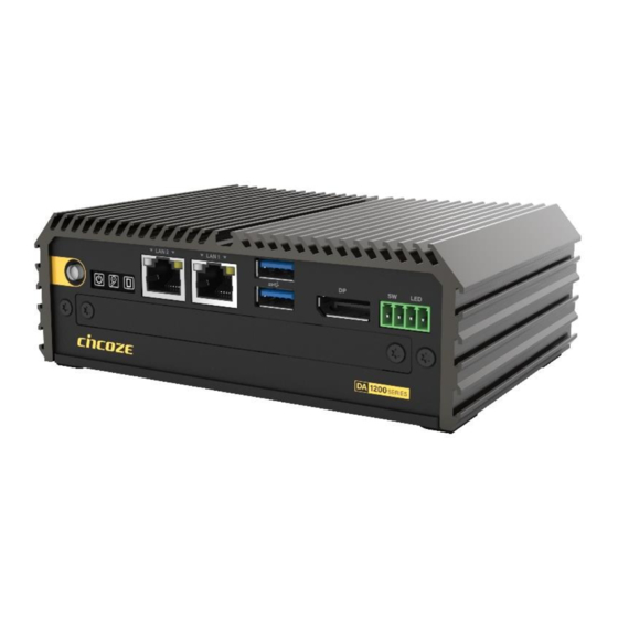
Page 12: Overview
1.1 Overview The palm-sized DA-1200, equipped with an Intel® N97 processor (Alder Lake-N platform), is the smallest and an affordable model in the DIAMOND product line. It inherits the rugged features consistent throughout the Cincoze lineup and has passed or complies with many international certification standards, such as EMC standards in industrial environments (IEC 61000-6-2 and IEC 61000-6-4) and US military shock vibration standards (MIL-STD-810H). - Page 13 Palm-Sized The DA-1200 measures 150 x 105 x 52.3 mm and can fit in the palm of your hand. Affordable High Performance The DA-1200 has an Intel® N97 processor based on the Intel® 7 process and up to 16GB of DDR5 memory, giving it excellent overall performance at a highly competitive price.
-
Page 14: Hardware Specification
Reliability & Protection • Yes Reverse Power Input Protection • Protection Range: 51-58V Over Voltage Protection • Protection Type: shut down operating voltage, re-power on at the present level to recover • 15A Over Current Protection DA-1200 Series | User Manual... - Page 15 • EN/IEC 61000-4-11 Voltage Dips & Voltage Interruptions: 1 cycles at 60 Hz * Product Specifications and features are for reference only and are subject to change without prior notice. For more information, please refer to the latest product datasheet from Cincoze's website. DA-1200 Series | User Manual...
-
Page 16: External Layout
Remote On/Off HDD LED LAN2 LAN1 Power On/Off Power LED GPIO LED DisplayPort USB 3.2 Gen2 x1 SIM Card Slot Clear CMOS Remote Reset Switch AT/ATX Switch Power LED 1.3.2 Rear DC IN Antenna Antenna DA-1200 Series | User Manual... -
Page 17: Dimensions
1.4 Dimensions Unit: mm DA-1200 Series | User Manual... -
Page 18: Chapter 2 Introduction To Switches & Connectors
Chapter 2 Introduction to Switches & Connectors DA-1200 Series | User Manual... -
Page 19: Location Of System Switches And Connectors
2.1 Location of System Switches and Connectors 2.1.1 Top View DC_IN1 CAP_PH1 PWR_SW1 LAN2 LAN1 USB3_1 PWR_SW2 GPIO_LED HDD_LED PWR_LED1 DA-1200 Series | User Manual... -
Page 20: Bottom View
2.1.2 Bottom View RESET1 CN13 SIM_BTB BTB_FH1 DA-1200 Series | User Manual... -
Page 21: Switches And Connectors Definition
SATA connector SIMA01 SIM Card socket AT/ATX Power Mode Switch, Clear CMOS Switch, SIM Card socket board-to- SIM_BTB board Connector SODIMM1 DDR5 SO-DIMM Connector Super CAP Control Switch USB3_1 Two USB 3.2 Gen2 X1 Connector DA-1200 Series | User Manual... -
Page 22: Definition Of Switches
Switch Definition Push Power up the System RESET1: System Reset Button Switch Definition Push Reset System SW1: Super CAP Control Switch Location Function DIP1 DIP2 Super CAP Enabled ON (Default) ON (Default) Super CAP Disabled DA-1200 Series | User Manual... -
Page 23: Definition Of Connectors
KEY Pin M.2_BT_PCMCLK CFG0 M.2_BT_PCMIN M.2_BT_PCMOUT M.2_BT_PCMFRM PCIE2_RXN/USB3 RXN USIM_RESET PCIE2_RXP/USB3 RXP USIM_CLK USIM_DATA PCIE2_TXN/USB3 TXN USIM_PWR PCIE2_TXP/USB3 TXP DEVSLP PCIE1_RXN/SATA_RXP PCIE1_RXP/SATA_RXN PCIE1_TXN/SATA_TXN PCIE1_TXP/SATA_TXP RESET# 100M_CLKN WAKE# 100M_CLKP SIM_DETECT RESET2# SUSCLK CFG1 +3.3V +3.3V +3.3V CFG2 DA-1200 Series | User Manual... - Page 24 KEY Pin KEY Pin KEY Pin KEY Pin KEY Pin KEY Pin KEY Pin M.2_BT_PCMCLK M.2_BT_PCMIN M.2_BT_PCMOUT M.2_BT_PCMFRM PCIE2_RXN PCIE2_RXP PCIE2_TXN PCIE2_TXP DEVSLP PCIE1_RXN PCIE1_RXP PCIE1_TXN PCIE1_TXP RESET# 100M_CLKN WAKE# 100M_CLKP RESET2# SUSCLK +3.3V +3.3V +3.3V DA-1200 Series | User Manual...
- Page 25 This port is used to connect a SWITCH! (Pour la télécommande de mise sous/hors tension (broche 1 et broche 2) : Ne fournissez aucune alimentation à ce connecteur ! Ce port est utilisé pour connecter un INTERRUPTEUR !) DA-1200 Series | User Manual...
-
Page 26: Optional Module Pin Definition & Settings
Connector Type: 9-pin D-Sub RS232 RS422 / 485 Full RS485 Half Definition Duplex Definition Duplex Definition DATA - DATA + COM34_SEL1 : COM3 and COM4 Power Select Switch Function COM3 7-9 (Default) COM4 8-10 (Default) DA-1200 Series | User Manual... -
Page 27: Cmi-Dio100 Module
2.5.2 CMI-DIO100 Module DIO1 (on the module): Digital IN Connector Connector Type: Terminal Block 1X10 10-pin, 3.5mm pitch Definition Definition XCOM+ (DC INPUT) XCOM- (GND) DA-1200 Series | User Manual... -
Page 28: Chapter 3 System Setup
Chapter 3 System Setup DA-1200 Series | User Manual... -
Page 29: Removing Top Cover
Step 1: Loosen the 4 screws on the bottom panel of the system. Step 2. Remove the bottom panel and then the system body from the chassis. Step 3. Place the system body aside gently. DA-1200 Series | User Manual... -
Page 30: Installing So-Dimm Memory
Step 2. Tilt the SO-DIMM module at a 45-degree angle and insert it to SO-DIMM socket until the gold-pated connector of module contacted firmly with the socket. 45° Step 3. Press the modules down until it’s fixed firmly by the two locking latches on each side. DA-1200 Series | User Manual... -
Page 31: Installing M.2 Key B Module
Step 2. Locate the M.2 Key B 3052 slot (CN1). Step 3. Insert the M.2 Key B module at a 45-degree angle and insert it to the slot until the gold- pated connector of module contacted firmly with the slot. 45° DA-1200 Series | User Manual... -
Page 32: Key B Type 3042
Step 4. Press down the module and fasten the screw to secure the module. 3.3.2 M.2 Key B type 3042 Step 1. Loosen the screws to remove the HDD bracket. Step 2. Locate the M.2 Key B 3052 slot (socket CN1). DA-1200 Series | User Manual... - Page 33 Step 4. Insert the M.2 Key B module at a 45-degree angle and insert it to the slot until the gold- pated connector of module contacted firmly with the slot. Step 5. Press down the module and fasten the screw to secure the module. DA-1200 Series | User Manual...
-
Page 34: Key B Type 2242
Step 2. Locate the M.2 Key B 2242 slot (socket CN13). Step 3. Insert the M.2 Key B module at a 45-degree angle and insert it to the slot until the gold- pated connector of module contacted firmly with the slot. 45° DA-1200 Series | User Manual... -
Page 35: Key E Type 2230
3.3.4 M.2 Key E type 2230 In this chapter, you'll learn how to install an M.2 Key E type 2230 device onto the DA-1200 system. To complete the installation, you'll need to purchase our M.2 Key B Type 2242 to M.2 Key E Type 2230 Adapter Card (Model: AC-BE01-R10). - Page 36 Step 3. Insert the M.2 Key B module at a 45-degree angle and insert it to the slot until the gold- pated connector of module contacted firmly with the slot. 45° Step 4. Press down the module and fasten the screw to secure the module. DA-1200 Series | User Manual...
-
Page 37: Installing Antenna(S)
Step 6. Press down the module and fasten the screw to secure the module. 3.4 Installing Antenna(s) Please refer to Chapter 3.3.1 to install a Wireless Module at connect CN1 before antenna installation. Step 1. Remove the antenna hole cover(s) on the rear panel of the system. DA-1200 Series | User Manual... - Page 38 Step 2. Have the antenna jack penetrate through the hole. Step 3. Put on the washer and fasten the nut with the antenna jack. Step 4. Assemble the antenna and antenna jack together. DA-1200 Series | User Manual...
-
Page 39: Installing Sata Hard Drive
Step 2. Make the PCB side of the HDD face up, place the HDD bracket on it. Ensure the direction of bracket is correct and use 4 provided screws to assemble HDD and HDD bracket together. DA-1200 Series | User Manual... -
Page 40: Installing A Half-Slim Ssd
Step 2. Make the PCB side of the HDD face up, place the HDD bracket on it. Ensure the direction of bracket is correct and use 4 provided screws to assemble HDD and HDD bracket together. DA-1200 Series | User Manual... -
Page 41: Bare Half-Slim Ssd Pcb
Step 3: Flip the HDD bracket over and connect it to the SATA connector, then fasten the four screws. 3.6.2 Bare Half-Slim SSD PCB Step 1. Loosen the screws to remove the HDD bracket. Step 2. Fasten the 4 copper pillars. DA-1200 Series | User Manual... -
Page 42: Installing Cpu Heatsink Thermal Pad
3.7 Installing CPU Heatsink Thermal Pad Step 1. Locate the CPU heatsink. Step 2. Remove the protective film from one side of the Thermal Pad and then place the thermal pad onto the CPU heatsink. DA-1200 Series | User Manual... -
Page 43: Installing Top Cover
(Avant d'assembler le couvercle du châssis du système, assurez-vous que le film protecteur sur le coussin thermique a été retiré !) 3.8 Installing Top Cover Step 1. Put the system body back into the chassis and then put on the bottom panel. DA-1200 Series | User Manual... -
Page 44: Installing Sim Card
5G/4G module at connect CN1 before the SIM card installation for the SIM application. Step 1. Loosen the 2 screws on the front panel without removing them to take off the cover plate. Step 2. Locate the SIM card slot. DA-1200 Series | User Manual... - Page 45 Step 3. Insert the SIM card into the SIM slot(s) with the gold contacts facing up. Please pay attention to the insert orientation as illustrated. Step 4. Fasten the 2 screws on the front panel. DA-1200 Series | User Manual...
-
Page 46: Installing Wall Mount
3.10 Installing Wall Mount The DA-1200 series offers a wall mount included with the system, allowing customers to install it on the wall in a convenient and economical way. Step 1. Locate the four screw holes on the bottom panel of the system. Attach the brackets by aligning them with the four screw holes, and use the provided four screws to secure the brackets on both sides of the system. -
Page 47: Installing Vesa Mount
3.11 Installing VESA Mount DA-1200 offers VESA Mount that customer can mount system with panel complying with VESA 75mm standard for various usage. Step 1. Align the stand with the screw holes on the system, then secure it in place by tightening the corresponding number of screws as shown below. -
Page 48: Installing Side Mount
3.12 Installing Side Mount The DA-1200 series offers an optional accessory for side mounting, Side Mount Kit (Model No. SIDE02) as shown below. If you have acquired this accessory, please refer to the installation instructions hereafter. Step 1. The mounting holes are at the bottom of system. Fasten the 4 screws (M3x4L) to fix the side mount bracket with system together. -
Page 49: Installing Din-Rail Mount
3.13 Installing DIN-Rail Mount 3.13.1 DIN-Rail Mount Clips (on Side Mount Bracket) DA-1200 series offers DIN-Rail Mount Clips (KMRH-K175) and side mount bracket that customer can install system on the DIN Rail. Step 1. Fasten 2 DIN rail mounting clips to the side mount bracket with provided 4 screws as illustrated. -
Page 50: Din-Rail Mounting Kit
3.13.2 DIN-Rail Mounting Kit DA-1200 series offers an optional accessory for DIN-Rail mounting, Side Mount Kit (Model No. DINRAIL-R10) as shown below. If you have acquired this accessory, please refer to the installation instructions hereafter. Step 1. Locate the two mounting holes for DIN-rail mounting on the bottom of system, and then fasten the 2 screws to fix the DIN-Rail mounting bracket with the system together. -
Page 51: Installing Cmi Modules
Step 2. Locate the BTB_FH1 connector on the top side of system. Step 3. Insert the CMI module vertically with aligning the pin holes. And then secure it with the two screws. Step 4. Attach the I/O bracket and fasten the screws to fix it. DA-1200 Series | User Manual... -
Page 52: Cmi-Dio100/Ub0415
Step 2. Locate the BTB_FH1 connector on the top side of system. Step 3. Insert the CMI module vertically with aligning the pin holes. And then secure it with the two screws. Step 4. Attach the I/O bracket and fasten the screws to fix it. DA-1200 Series | User Manual... -
Page 53: Cmi-Dp101/Ub0406
Step 4. Attach the I/O bracket on to the system, and fasten the screws to fix it. Please ensure the Graphics Configuration in the BIOS is set appropriately for successful display from this module. DA-1200 Series | User Manual... -
Page 54: Cmi-Dvi101/Ub0407
Step 4. Attach the I/O bracket on to the system, and fasten the screws to fix it. Please ensure the Graphics Configuration in the BIOS is set appropriately for successful display from this module. DA-1200 Series | User Manual... -
Page 55: Cmi-Hd01/Ub0408
Step 4. Attach the I/O bracket on to the system, and fasten the screws to fix it. Please ensure the Graphics Configuration in the BIOS is set appropriately for successful display from this module. DA-1200 Series | User Manual... -
Page 56: Cmi-Vga101/Ub0416
Step 4. Attach the I/O bracket on to the system, and fasten the screws to fix it. Please ensure the Graphics Configuration in the BIOS is set appropriately for successful display from this module. DA-1200 Series | User Manual... -
Page 57: Cmi-Lpps102/Ub0409
Step 3. Thread the module through the cavity designated for I/O bracket with an inclined angle and insert the CMI module vertically with aligning the right 76 pin holes. Step 4. Secure it with the two screws. DA-1200 Series | User Manual... -
Page 58: Ub0429-R10
Step 1. Loosen the 2 screws on the rear panel without removing them to take off the cover plate. Step 2. Attach the I/O bracket on to the system, and fasten the screws to fix it. For guidance on antenna installation methods, please refer to Chapter 3.4. DA-1200 Series | User Manual... -
Page 59: Chapter 4 Bios Setup
Chapter 4 BIOS Setup DA-1200 Series | User Manual... -
Page 60: Bios Introduction
( ↑↓ ) to highlight the field and press <Enter> to call up the sub-menu. Then you can use the control keys to enter values and move from field to field within a sub-menu. If you want to return to the main menu, just press the <Esc >. DA-1200 Series | User Manual... -
Page 61: Main Setup
Use arrow keys to move among the items and press <Enter> to accept or enter a sub-menu. ◼ System Date Set the date. Please use <Tab> to switch between date elements. ◼ System Time Set the time. Please use <Tab> to switch between time elements. DA-1200 Series | User Manual... -
Page 62: Advanced Setup
Enables or disables Intel Virtualization Technology. Virtualization enhanced by Intel Virtualization Technology will allow a platform to run multiple operating systems and applications in independent partitions. With virtualization, one computer system can function as multiple virtual systems. DA-1200 Series | User Manual... -
Page 63: Sata Configuration
SATA Controller(s) [Enabled] Enables or disables SATA device. ◼ Serial ATA Port 0 Port 0 [Enabled] Enables or disables SATA Port 0. ◼ Serial ATA Port 1 Port 1 [Enabled] Enables or disables SATA Port 1. DA-1200 Series | User Manual... -
Page 64: Pch-Fw Configuration
4.3.3 PCH-FW Configuration ◼ Firmware Update Configuration Configure Management Engine Parameters ◼ Me FW Image Re-Flash [Disabled] Enables or disables ME firmware Image Re-Flash function. DA-1200 Series | User Manual... -
Page 65: Trusted Computing Settings
Enables or disables Storage Hierarchy function. ◼ Endorsement Hierarchy [Enabled] Enables or disables Endorsement Hierarchy function. ◼ Physical Presence Spec Version [1.3] Allows you to select which mode Physical Presence Spec Version will operate. Configuration options: [1.2], [1.3] DA-1200 Series | User Manual... -
Page 66: Acpi Settings
Allows users to select the highest Advanced Configuration Power Interface® (ACPI) sleep state that system will enter when suspend button is pressed. [Suspend Disabled]: Disables entering suspend state. [S3 (suspend to RAM)]: Enables suspend to RAM state. DA-1200 Series | User Manual... -
Page 67: F81966 Super Io Configuration
Serial Port 1 Configuration. ◼ Serial Port [Enabled] Enables or disables serial port. ◼ Change Settings [Auto] Allows you to change the IO Address & IRQ settings of the specified serial port. ◼ Serial Port Mode [RS232] DA-1200 Series | User Manual... - Page 68 Allows you to change the IO Address & IRQ settings of the specified serial port. ◼ Serial Port Mode [RS232] Allows you to select Serial Port Mode. Configuration options: [RS232] [RS422/RS485 Full Duplex] [RS485 Half Duplex] DA-1200 Series | User Manual...
- Page 69 SPP Mode] [ECP Mode] [ECP and EPP 1.9 Mode] [ECP and EPP 1.7 Mode] ◼ Watch Dog Mode [Sec] Allows to set watchdog timer unit <Sec> or <Min>. ◼ Watch Dog Timer [0] Allows you to set watchdog timer’s value in the range of 0 to 255. DA-1200 Series | User Manual...
-
Page 70: Hardware Monitor
Enables or disables wake system from S5 (soft-off state). [Disabled]: Disables wake system from S5. [Fixed Time]: Sets a fixed time (HH:MM:SS) to wake system from S5. [Dynamic Time]: Sets an increase minute(s) from current time to wake system from S5. DA-1200 Series | User Manual... -
Page 71: Serial Port Console Redirection
Enables or disables XHCI (USB3.0) hand-off function. Use this feature as a workaround for operating systems without XHCI hand-off support. ◼ USB Mass Storage Driver Support [Enabled] Enables or disables USB mass storage driver support. DA-1200 Series | User Manual... -
Page 72: Network Stack Configuration
4.3.11 Network Stack Configuration ◼ Network Stack [Disabled] Enables or disables UEFI Network Stack. 4.3.12 CSM Configuration ■ CSM Support [Disabled] Enables or disables compatibility support module. DA-1200 Series | User Manual... -
Page 73: Nvme Configuration
The screen allows users to select options for the NVMe configuration, and change the value of the selected option. If there is NVMe Device detected, the options will show as the NVMe Device is found. 4.4 Chipset Setup This section allows you to configure chipset related settings according to user’s preference. DA-1200 Series | User Manual... -
Page 74: System Agent (Sa) Configuration
4.4.1 System Agent (SA) Configuration ◼ Memory Configuration This item displays detailed memory configuration in the system. DA-1200 Series | User Manual... - Page 75 This option enables users to choose the type of CMI Module. The default setting is VGA/DVI/DP. If the CMI-HDMI module is utilized, kindly ensure to configure this function as [HDMI] to ensure successful display from the CMI-HDMI module. Configuration options: [VGA/DVI/DP] [HDMI] DA-1200 Series | User Manual...
-
Page 76: Pch-Io Configuration
◼ PCIe Speed [Auto] Allows you to select PCI Express interface speed. Configuration options: [Auto] [Gen1] [Gen2] [Gen3]. ◼ PCI Express Root Port (CN1) ◼ PCI Express Root Port [Enabled] Enables or disables PCI Express Root Port. DA-1200 Series | User Manual... -
Page 77: Security Setup
[Always on]: Enters to power on state. [Always off]: Enters to power off state. [Keep last state]: Enters to the last power state before a power failure. 4.5 Security Setup This section allows users to configure BIOS security settings. DA-1200 Series | User Manual... - Page 78 ◼ Administrator Password Administrator Password controls access to the BIOS Setup utility. ◼ User Password User Password controls access to the system at boot and to the BIOS Setup utility. ◼ Security Boot DA-1200 Series | User Manual...
-
Page 79: Boot Setup
Allows you to enable or disable Quiet Boot function. ◼ Fast Boot Allows you to enable or disable Fast Boot function. If enabled, system boots with initialization of a minimal set of devices required to launch active boot option. DA-1200 Series | User Manual... -
Page 80: Save & Exit
Save as User Defaults This item allows you to save the changes done so far as user defaults. ◼ Restore User Defaults This item allows you to restore the user defaults to all the setup options. DA-1200 Series | User Manual... -
Page 81: Chapter 5 Product Application
Chapter 5 Product Application DA-1200 Series | User Manual... -
Page 82: Where To Download Drivers
5.1 Where to download drivers? Please go to the CINCOZE website to download the drivers for DA-1200 series. 5.2 Where to find the technical documents? Please go to the CINCOZE website to find the technical documents for DA-1200 series. Catalog... - Page 83 © 2024 Cincoze Co., Ltd. All rights reserved. The Cincoze logo is a registered trademark of Cincoze Co., Ltd. All other logos appearing in this catalog are the intellectual property of the respective company, product, or organization associated with the logo.
Need help?
Do you have a question about the DA-1200 and is the answer not in the manual?
Questions and answers