
Related Manuals for Cincoze DA-1000 Series


Summary of Contents for Cincoze DA-1000 Series
- Page 1 DA-1000 Series User Manual Fanless Computing Solution Intel® Atom™ or Celeron® Processor Affordable Fanless Embedded Computer Version: V1.52...
-
Page 2: Table Of Contents
2.1.1 Top View ……………………………….……………………………………...………..20 2.1.2 Bottom View ……………………………………………………………...……....21 2.2 Switches and Connectors Definition…………………..….……………………………….22 2.3 Definition of Switches.……...……………..........……....23 2.4 Definition of Connectors …...….……...……….....………………......24 Chapter 3 System Setup 3.1 Removing the Top Cover ……...……………………………….….…………………..29 3.2 Installing SO-DIMM Memory………………………..…………..…………….……………31 DA-1000 Series | User Manual... - Page 3 4.3.10 USB Configuration………….…………………………………………………..59 4.4 Chipset Setup …...……….…………………..…..….…..…………………………………...60 4.4.1 North Bridge ……………………………………..……………………………………..60 4.4.2 South Bridge…………….……………….……………………………………………..62 4.5 Security Setup …...……….………………….…..………………..……………………...…64 4.5.1 Administrator Password …….…...……………………………………………………64 4.5.2 User Password …….…………………………………………………..………………64 4.6 Boot Setup …...……….….……………………………...…..….…..………..…………..65 4.7 Save & Exit …...……….….………………….…..….…..………………………....66 DA-1000 Series | User Manual...
- Page 4 Chapter 5 Product Application (For CMI-DIO100 Only) 5.1 Digital I/O (DIO) application ………..………………………………………………………68 5.1.1 Digital I/O Programming Guide ……………………………………………………68 5.2 Digital I/O (DIO) Hardware Specification ……………………………………………………73 5.2.1 DIO Connector Definition ………………..……...…………….........74 DA-1000 Series | User Manual...
-
Page 5: Revision
2020/09/10 Copyright Notice © 2016 by Cincoze Co., Ltd. All rights are reserved. No parts of this manual may be copied, modified, or reproduced in any form or by any means for commercial use without the prior written permission of Cincoze Co., Ltd. All information and specification provided in this manual are for reference only and remain subject to change without prior notice. -
Page 6: Product Warranty Statement
Product Warranty Statement Warranty Cincoze products are warranted by Cincoze Co., Ltd. to be free from defect in materials and workmanship for 2 years from the date of purchase by the original purchaser. During the warranty period, we shall, at our option, either repair or replace any product that proves to be defective under normal operation. -
Page 7: Technical Support And Assistance
Limitation of Liability Cincoze’ liability arising out of the manufacture, sale, or supplying of the product and its use, whether based on warranty, contract, negligence, product liability, or otherwise, shall not exceed the original selling price of the product. The remedies provided herein are the customer’s sole and exclusive remedies. -
Page 8: Conventions Used In This Manual
11. If the equipment is not used for a long time, disconnect it from the power source to avoid damage by transient overvoltage. 12. Never pour any liquid into an opening. This may cause fire or electrical shock. DA-1000 Series | User Manual... - Page 9 The equipment has obvious signs of breakage. ⚫ 14. CAUTION: Danger of explosion if battery is incorrectly replaced. Replace only with the same or equivalent type recommended by the manufacturer. 15. Equipment intended only for use in a RESTRICTED ACCESS AREA. DA-1000 Series | User Manual...
-
Page 10: Package Contents
Note: Notify your sales representative if any of the above items are missing or damaged. Ordering Information Model No. Product Description Intel® Atom™ Processor E3826 Affordable Fanless Embedded DA-1000 Computer Intel® Atom™ Processor E3845 Affordable Fanless Embedded DA-1000-E45 Computer Intel® Celeron® Processor J1900 Affordable Fanless Embedded DA-1000-J19 Computer DA-1000 Series | User Manual... -
Page 11: Optional Modules & Accessories
Mini-PCIe Module with 2x LAN Ports, 1x Universal Bracket (96 B0411 x 15 mm) MEC-USB-M002/UB04 Mini-PCIe Module with 2x USB 3.0 Ports, 1x Universal Bracket (96 x 15 mm) SIDE-DA DA Series Side Mount Kit DINRAIL Diamond Series Din-Rail Mount Kit DA-1000 Series | User Manual... -
Page 12: Chapter 1 Product Introductions
Chapter 1 Product Introductions DA-1000 Series | User Manual... -
Page 13: Overview
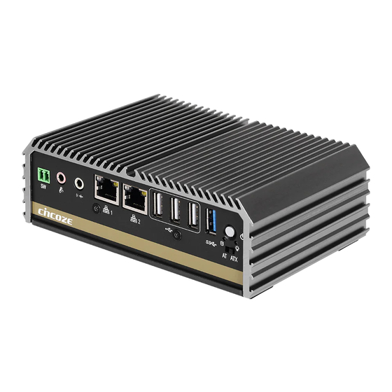
1.1 Overview DA-1000 Series is an ultra-compact size fanless embedded computer powered by Intel® Atom™ or Celeron® Processors; it integrated HD graphics processor supporting dual display. This can bring economic advantages on budget and also fulfill the needs for industrial computing tasks. DA-1000 Series manages to pack a diverse array of I/O into its small form factor, with one DVI-I port, two RS-232/422/485 COM ports, dual Gbe LAN ports, four USB ports and one set of Mic-in and Line-out. -
Page 14: Product Pictures
1.3 Product pictures Front Rear DA-1000 Series | User Manual... -
Page 15: Hardware Specification
• 1x SIM Socket (Internal) (With SSD According to IEC 60068-2-64, • 1x CMI (Combined Multiple I/O) Interface 5~500Hz, 1 hr/axis) Certification Watchdog Timer • Software Programmable Supports 256 Levels • CE System Reset • FCC Class A DA-1000 Series | User Manual... -
Page 16: System I/O
Indicates the status of the hard drive Mic-in Remote Power Terminal Block Used to connect a microphone Used to plug a remote power on/off switch Line-out with terminal block Used to connect a speaker DA-1000 Series | User Manual... -
Page 17: Rear
Universal I/O Bracket This expansion area is reserved for Mini-PCIe expansion or Cincoze own pin-defined interface (CMI). CMI interface supports various type of I/O modules such as COM / DIO / DisplayPort / DVI / LPT & PS2 / VGA. -
Page 18: Mechanical Dimension
1.6 Mechanical Dimension Unit: mm DA-1000 Series | User Manual... - Page 19 Chapter 2 Switches & Connectors DA-1000 Series | User Manual...
-
Page 20: Location Of Switches And Connectors
2.1 Location of Switches and Connectors 2.1.1 Top View DA-1000 Series | User Manual... -
Page 21: Bottom View
2.1.2 Bottom View DA-1000 Series | User Manual... -
Page 22: Switches And Connectors Definition
MIC_IN1 Microphone-in Jack MINIPCIE1 Mini PCI-Express Socket PWR_SW2 External Power Connector SATA1 SATA with Power Connector SIM1 SIM Card Socket (apply with MINIPCIE1) USB2_1 / USB2_2 / USB2_3 USB 2.0 Connector USB3_1 USB 3.0 Connector DA-1000 Series | User Manual... -
Page 23: Definition Of Switches
AT_ATX1: AT / ATX Power Mode Switch Switch Definition ATX Power Mode(Default) Right Left AT Power Mode CLR_CMOS1: Clear CMOS Switch Switch Definition Clear CMOS 1 (OFF) Normal Status (Default) PWR_SW1:Power Switch Switch Definition Push Power on/off System DA-1000 Series | User Manual... -
Page 24: Definition Of Connectors
2.4 Definition of Connectors CN1:Mini PCI-Express / mSATA Socket Pin Definition Pin Definition Pin Definition WAKE# +3.3V +3.3V USB_6P +3.3V MINIPCIE RST# MINIPCIE_RXN3/SATA_RXP1 +3.3V +1.5V +3.3V CLKREQ# MINIPCIE_RXP3/SATA_RXN1 +1.5V MINIPCIE_CLKN3 SMB_CLK +1.5V MINIPCIE_CLKP3 MINIPCIE_TXN3/SATA_TXN1 SMB_DATA MINIPCIE_TXP3/SATA_TXP1 +3.3V USB_6N DA-1000 Series | User Manual... - Page 25 MINIPCIE1 : Mini PCI-Express Socket DA-1000 Series | User Manual...
- Page 26 Chassis GND LAN1 / LAN2: LAN LED Status Definition Act LED Status Definition Blinking Yellow Data Activity No Activity Link LED Status Definition Steady Green 1Gbps Network Link Steady Orange 100Mbps Network Link 10Mbps Network Link DA-1000 Series | User Manual...
- Page 27 Full Duplex Half Duplex Definition Definition Definition DATA - DATA + NOTE: (For CMI-COM102 only) The optional CMI module having 2 COM ports <RS232 / RS422 / RS485> is with +5/+12VDC for RI pin (Pin 9). DA-1000 Series | User Manual...
-
Page 28: Chapter 3 System Setup
Chapter 3 System Setup DA-1000 Series | User Manual... -
Page 29: Removing The Top Cover
3.1 Removing the Top Cover 1. Turn over the unit to have the bottom side face up, loosen the 4 screws of bottom cover and place them aside. 2. Remove the bottom cover from the chassis. DA-1000 Series | User Manual... - Page 30 (right picture) as marked on photo and place them aside. 4. Hold front and rear panel and lift up the body of unit vertically. 5. Turn over the body of the unit and place it gently. DA-1000 Series | User Manual...
-
Page 31: Installing So-Dimm Memory
2. Tilt the SO-DIMM module at a 45-degree angle and insert it to SO-DIMM socket until the gold-pated connector of module contacted firmly with the socket. 45° 3. Press the modules down until it’s fixed firmly by the two locking latches on the sides. DA-1000 Series | User Manual... -
Page 32: Installing Mini-Pcie Cards On Bottom Side
Turn over the body of unit. Unscrew the 3 screws on HDD bracket and remove the bracket. Locate the Mini PCIe slots. Please note that the left connector is shared mSATA/Mini-PCIe interface, and right connector (with SIM socket underneath) is Mini-PCIe interface. DA-1000 Series | User Manual... - Page 33 Press down the module and fasten two screws to secure the module. If you have a Half-size Mini-PCIe card, make sure use extender to make it Full-size as shown below. DA-1000 Series | User Manual...
-
Page 34: Installing A Sata Hard Drive
3 provided screws to assemble HDD and HDD bracket together. 3. Turn over the HDD bracket. Connect the HDD bracket to the SATA connector of the unit and fasten the 3 screws. DA-1000 Series | User Manual... -
Page 35: Installing Antennas
3.5 Installing Antennas 1. Remove the antenna rubber covers on rear panel. 2. Have antenna jack penetrate through the hole. 3. Put on washer and fasten the nut with antenna jack. DA-1000 Series | User Manual... - Page 36 4. Assemble the antenna and antenna jack together. 5. Attach the RF connector at another end of cable onto the module. DA-1000 Series | User Manual...
-
Page 37: Assembling The System
2. Make sure the either sides of front and rear panels are in the chassis grooves and insert the body of unit into Chassis. Use the 3 screws to fasten the body and chassis together. DA-1000 Series | User Manual... - Page 38 3. Level the grooves on bottom cover with front and rear panels. Put on the cover. 4. Fasten the 4 screws to fix the cover. DA-1000 Series | User Manual...
-
Page 39: Installing A Sim Card
3.7 Installing a SIM Card 1. Locate the SIM card socket. 2. Insert the SIM card. 3. Press down the socket of SIM card to lock the location. DA-1000 Series | User Manual... -
Page 40: Wall Mount Brackets
1. The mounting holes are at the bottom side of system. Use provided 4 screws to fasten the bracket with each side on system together. 2. Fasten the screws through the bracket mounting hole to mount system on the wall. DA-1000 Series | User Manual... -
Page 41: Side Mount Bracket
1. The mounting holes are at the bottom of system. Remove the 2 screws at right side of bottom plate. 2. Replace them with 2 longer flat-head screws that come with the side mount screw pack. DA-1000 Series | User Manual... - Page 42 3. Place the side mount bracket on bottom of system as picture below, and fasten the rest of 4 screws to fix it with system together. 4. Fasten the screws through the bracket mounting hole to mount system on the wall. DA-1000 Series | User Manual...
-
Page 43: Din-Rail Mount Bracket
DA-1000 offers DIN-Rail Mount Bracket that customer can install system on the DIN Rail. 1. The mounting holes are at the bottom of system. Fasten the 2 screws to fix the DIN-Rail mount bracket with system together. DA-1000 Series | User Manual... -
Page 44: Vesa Mount Bracket
DA-1000 offers VESA Mount that customer can mount system with panel complying with VESA 75mm standard for various usage. 1. Provided below is the base of the system unit and screw holes specified to be mounted from VESA stand. 2. Provided below is mounted with VESA stand. DA-1000 Series | User Manual... - Page 45 3. Provided below is completion of mounting with VESA stand. DA-1000 Series | User Manual...
-
Page 46: Chapter 4 Bios Setup
Chapter 4 BIOS Setup DA-1000 Series | User Manual... -
Page 47: Bios Introduction
You can use arrow keys ( ↑↓ ) to highlight the field and press <Enter> to call up the sub-menu. Then you can use the control keys to enter values and move from field to field within a sub-menu. If you want to return to the main menu, just press the <Esc >. DA-1000 Series | User Manual... -
Page 48: Main Setup
Use arrow keys to move among the items and press <Enter> to accept or enter a sub-menu. 4.2.1 System Date Set the date. Please use <Tab> to switch between date elements. 4.2.2 System Time Set the time. Please use <Tab> to switch between time elements. DA-1000 Series | User Manual... -
Page 49: Advanced Setup
This section allows you to configure and improve your system and allows you to set up some system features according to your preference. 4.3.1 ACPI Settings ■ Enable ACPI Auto Configuration [Disabled] Enables or disables BIOS Advanced Configuration Power Interface® (ACPI) auto configuration. DA-1000 Series | User Manual... -
Page 50: Super Io Configuration
■ Watch Dog Timer [0] Allows you to set watchdog timer’s value in the range of 0 to 255. We’ll use serial port 1 configuration as an example in the manual. Similar settings apply to other serial ports configuration. DA-1000 Series | User Manual... - Page 51 Entering serial port 1 configuration allows you to enable or disable the port, and also to configure settings and mode of operations. To avoid conflicted setting with other serial ports, default setting is recommended. DA-1000 Series | User Manual...
- Page 52 Entering parallel port configuration allows you to enable or disable the port, and also to configure settings and mode of device operation. Default setting is recommended. DA-1000 Series | User Manual...
-
Page 53: Hardware Monitor
4.3.4 Serial Port Console Redirection This allows you to enable and disable serial (COM) port(s) for console use. Default setting is disabled. ■ Console Redirection [Disabled] Allow users to enable or disable COM1, COM2, COM3, COM4 console redirection function. DA-1000 Series | User Manual... -
Page 54: Cpu Configuration
■ Socket 0 CPU Information This section provides information on your CPU, frequency, and cache memory. ■ Limit CPUID Maximum Default is Disabled. ■ Execute Disable Bit Default is Enabled. ■ Intel Virtualization Technology Default is Enabled. DA-1000 Series | User Manual... -
Page 55: Thermal Configuration
This allows 90C (default), 87C, 85C, 79C, 71C, 63C, 55C, 47C, 39C, 31C, 23C, 15C. ■ Passive Trip Point This allows 90C, 87C, 85C (default), 79C, 71C, 63C, 55C, 47C, 39C, 31C, 23C, 15C. ■ DTS Default is Disabled. DA-1000 Series | User Manual... -
Page 56: Sata Configuration
Use of default setting is recommended in the section. ■ SATA Mode This allows to set AHCI mode (default) or IDE mode. ■ Serial-ATA Port 0 Default is Enabled. ■ Serial-ATA Port 1 Default is Enabled. DA-1000 Series | User Manual... -
Page 57: Os Selection
This allows to set All Other OS or Windows 7 (default). 4.3.9 CSM Configuration Following shows default settings. ■ CSM Support Enables or disables UEFI CSM (Compatibility Support Module) to support a legacy PC boot process. DA-1000 Series | User Manual... - Page 58 Allows user to select whether to enable the UEFI or legacy option ROM for the Video device controller. Do not launch: Disables option ROM. UEFI: Enables UEFI option ROM only. Legacy: Enables legacy option ROM only. DA-1000 Series | User Manual...
-
Page 59: Usb Configuration
XHCI (USB3.0) Hand-off support. ■ EHCI Hand-off Determines whether to enable EHCI Hand-off feature for an operating system without EHCI Hand-off support. ■ USB Mass Storage Driver Support Enables or disables support for USB storage devices. DA-1000 Series | User Manual... -
Page 60: Chipset Setup
This section allows you to configure chipset related settings according to user’s preference. 4.4.1 North Bridge This section provides information on the installed memory size and memory/onboard graphics-related configuration options. ■ Intel IGD Configuration This section provides onboard graphics-related configuration options. Following is default setting. DA-1000 Series | User Manual... - Page 61 This item will allow users to enable or disable DOP CG. ❑ GTT Size GTT size optimal between 1MB or 2MB. ❑ IGD Thermal This item will allow users to enable or disable IGD Thermal. DA-1000 Series | User Manual...
-
Page 62: South Bridge
This item will allow users to enable or disable USB Port 2. ❑ USB Port 3 This item will allow users to enable or disable USB Port 3. ■ PCI Express Configuration ❑ PCI Express Port 0 DA-1000 Series | User Manual... - Page 63 ■ Mini PCIe/mSATA Select This allows to set shared Mini PCIe slot for use as either Mini PCIe (default) or mSATA interface. ■ Wake on LAN Enable This enables or disables Wake on LAN feature. Default is Enabled. DA-1000 Series | User Manual...
-
Page 64: Security Setup
4.5.1 Administrator Password Administrator Password controls access to the BIOS Setup utility. 4.5.2 User Password User Password controls access to the system at boot and to the BIOS Setup utility. DA-1000 Series | User Manual... -
Page 65: Boot Setup
This item allows user to enable or disable full screen logo show. ■ Fast Boot This item allows user to enable or disable Fast Boot option. ■ UEFI Boot This allows to boot device with UEFI-based (not legacy) OS. DA-1000 Series | User Manual... -
Page 66: Save & Exit
■ Save as User Defaults This item allows you to save the changes done so far as user defaults. ■ Restore User Defaults This item allows you to restore the user defaults to all the setup options. DA-1000 Series | User Manual... -
Page 67: Chapter 5 Product Application (For Cmi-Dio100 Only)
Chapter 5 Product Application (For CMI-DIO100 only) DA-1000 Series | User Manual... -
Page 68: Digital I/O (Dio) Application
The configuration register is used to control the behavior of the corresponding devices. To configure the register, use the index port to select the index and then write data port to alter the parameters. The default index port and data port are 0x4E and 0x4F, respectively. DA-1000 Series | User Manual... - Page 69 Following is an example to enable configuration and to disable configuration by using debug. -o 4e 87 -o 4e 87 (enable configuration) -o 4e aa (disable configuration) 5.1.1.3 Relative Registers To program the F81866A configuration registers, see the following configuration procedures. DA-1000 Series | User Manual...
- Page 70 WriteByte(DataPort, (ReadByte(DataPort) ǀ 0x0X)) // Set (bit 4~7) = 0 to select GP 54~57 as Input mode. <Input Value> WriteByte(AddrPort, 0xA1) // Select configuration register A1h ReadByte(DataPort, Value) // Read bit 4~7 (0xFx)= GP54 ~57 as High. DA-1000 Series | User Manual...
- Page 71 // Must write twice to enter Extended mode <Select Logic Device> WriteByte(AddrPort, 0x07) WriteByte(dataPort, 0x06) // Select logic device 06h WriteByte(AddrPort, 0x60) // Select configuration register 60h WriteByte(DataPort, (ReadByte(DataPort) ǀ 0x03)) WriteByte(AddrPort, 0x61) // Select configuration register 61h WriteByte(DataPort, (ReadByte(DataPort) ǀ 0x20)) DA-1000 Series | User Manual...
- Page 72 7 6 5 4 3 2 1 0 1 0 0 0 - - - - value - - - - 1 0 0 0 value DIO I/O Port Address 5.1.1.7 Pin Definition Data Bits 0xA05 0xA03 I/O Port address DA-1000 Series | User Manual...
-
Page 73: Digital I/O (Dio) Hardware Specification
DO Signal have to pull up resistor to XCOM+ for external device, the resistance will affect the pull up current Signal High Level: Pull up resistor to XCOM+ Signal Low Level: = XCOM- Sink Current: 1A (Max) DA-1000 Series | User Manual... -
Page 74: Dio Connector Definition
5.2.1 DIO Connector Definition DIO1: Digital Input / Output Connector Connector Type: Terminal Block 1X10 10-pin, 3.5mm pitch Definition XCOM+ XCOM- Pin 1 Pin 1 DA-1000 Series | User Manual... - Page 75 © 2020 Cincoze Co., Ltd. All rights reserved. The Cincoze logo is a registered trademark of Cincoze Co., Ltd. All other logos appearing in this catalog are the intellectual property of the respective company, product, or organization associated with the logo.
Need help?
Do you have a question about the DA-1000 Series and is the answer not in the manual?
Questions and answers