
Related Manuals for Cincoze DI-1200 Series


Summary of Contents for Cincoze DI-1200 Series
- Page 1 DI-1200 Series User Manual Rugged Embedded Computer 12th Generation Intel® Core™ U Series High Performance, Compact and Modular Rugged Embedded Computer Version: V1.00...
-
Page 2: Table Of Contents
2.5.6 CMI-XM12LAN01-R10 Module .................. 29 2.5.7 CMI-10GLAN04-R10 Module ..................29 Chapter 3 System Setup ........................30 3.1 Removing Top Cover ......................31 3.2 Installing SO-DIMM Memory ....................32 3.3 Installing M.2 Key B Module ....................33 DI-1200 Series | User Manual... - Page 3 4.3.5 ACPI Settings ......................78 4.3.6 F81966 Super IO Configuration ................. 79 4.3.7 Hardware Monitor ....................80 4.3.8 S5 RTC Wake Settings ....................81 4.3.9 Serial Port Console Redirection ................. 82 4.3.10 USB Configuration ....................82 DI-1200 Series | User Manual...
- Page 4 4.6 Boot Setup ..........................91 4.7 Save & Exit ..........................92 4.8 MEBx ............................ 93 Chapter 5 Product Application ......................96 5.1 Where to download drivers? ....................97 5.2 Where to find the technical documents? ................97 DI-1200 Series | User Manual...
-
Page 5: Preface
2024/01/31 Copyright Notice © 2024 by Cincoze Co., Ltd. All rights are reserved. No parts of this manual may be copied, modified, or reproduced in any form or by any means for commercial use without the prior written permission of Cincoze Co., Ltd. All information and specification provided in this manual are for reference only and remain subject to change without prior notice. -
Page 6: Product Warranty Statement
Before sending your product in, you will need to fill in Cincoze RMA Request Form and obtain an RMA number from us. Our staff is available at any time to provide you with the most friendly and immediate service. -
Page 7: Technical Support And Assistance
Limitation of Liability Cincoze’ liability arising out of the manufacture, sale, or supplying of the product and its use, whether based on warranty, contract, negligence, product liability, or otherwise, shall not exceed the original selling price of the product. The remedies provided herein are the customer’s sole and exclusive remedies. -
Page 8: Conventions Used In This Manual
11. If the equipment is not used for a long time, disconnect it from the power source to avoid damage by transient overvoltage. 12. Never pour any liquid into an opening. This may cause fire or electrical shock. DI-1200 Series | User Manual... -
Page 9: Package Checklist
9-48 VDC with minimum rated maximum ambient temperature 70°C, and has to be evaluated according to IEC/EN 60950-1 and/or IEC/EN 62368-1. If need further assistance, please contact Cincoze for further information. 17. Ensure to connect the power cord of power adapter to a socket-outlet with earthing connection. -
Page 10: Ordering Information
12th Generation Intel Core i7-1265UE High Performance, Compact and DI-1200-i7-R10 Modular Rugged Embedded Computer 12th Generation Intel Core i5-1245UE High Performance, Compact and DI-1200-i5-R10 Modular Rugged Embedded Computer 12th Generation Intel Core i3-1215UE High Performance, Compact and DI-1200-i3-R10 Modular Rugged Embedded Computer DI-1200 Series | User Manual... -
Page 11: Chapter 1 Product Introductions
Chapter 1 Product Introductions DI-1200 Series | User Manual... -
Page 12: Overview
The DI-1200 has a footprint smaller than a sheet of A5 paper, with dimensions of only 203 x 142 x 66.8 mm. It is ideal for mobile devices such as AGVs and AMRs, tight spaces in vehicles, or small cabinets in factories. DI-1200 Series | User Manual... - Page 13 It complies with industrial EMC standards (IEC 61000-6-2 and IEC 61000-6-4), ensuring reliable operation in external electromagnetic interference from surrounding devices. The DI-1200 also meets the U.S. military standard, MIL-STD-810H, ensuring stable operation under extreme shock and vibration conditions. DI-1200 Series | User Manual...
-
Page 14: Hardware Specification
• 1x Remote Power On/Off, 2-pin Terminal Block Remote Power On/Off • 1x Remote Power LED, 2-pin Terminal Block Remote Power LED Physical • 203 x 142 x 66.8 mm Dimension (W x D x H) • 1.8 KG Weight Information DI-1200 Series | User Manual... - Page 15 • EN/IEC 61000-4-11 Voltage Dips & Voltage Interruptions: 1 cycles at 60 Hz * Product Specifications and features are for reference only and are subject to change without prior notice. For more information, please refer to the latest product datasheet from Cincoze's website. DI-1200 Series | User Manual...
-
Page 16: External Layout
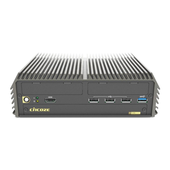
HDMI 2.5” Hot Swap HDD/SSD Bay IGN Setting Switch Reset Button On/Off 1.3.2 Rear Antenna Antenna LAN2 USB 3.2 Gen1 COM 2 Line-Out DC IN LAN1 COM 1 Mic-in Remote Power LED Remote Power On/Off DI-1200 Series | User Manual... -
Page 17: Dimensions
1.4 Dimensions Unit: mm DI-1200 Series | User Manual... -
Page 18: Chapter 2 Introduction To Switches & Connectors
Chapter 2 Introduction to Switches & Connectors DI-1200 Series | User Manual... -
Page 19: Location Of System Switches And Connectors
2.1 Location of System Switches and Connectors 2.1.1 Top View AUDIO1 COM1/1 DC_IN1 USB3_3 DUALDP1 CAP_PH1 DEBUG GDC1 BTB_FH1 BAT1 USB2_3 USB2_2 USB3_2 PWR_SW1 LED1 BTB_FH2 USB2_1 JHDMI1 2.1.2 Bottom View SATA2 IGN_PH1 RESET1 RTC1 AT_ATX1 SIM1 SIM2 DI-1200 Series | User Manual... -
Page 20: Switches And Connectors Definition
Super CAP Control Switch USB2_1 USB2.0 1-Port TYPE A connector USB2_2 USB2.0 1-Port TYPE A connector USB2_3 USB2.0 1-Port TYPE A connector USB3_2 USB3.2 GEN2 x1 1-Port TYPE A connector USB3_3 USB3.2 GEN1 x1 2-Port TYPE A connector DI-1200 Series | User Manual... -
Page 21: Definition Of Switches
Colorless POWER OFF Blinking Green Stand by Yellow HDD Read/Write HDD LED Colorless No Operation PWR_SW1: System Power Button Switch Definition Push Power up the System RESET1: System Reset Button Switch Definition Push Reset System DI-1200 Series | User Manual... -
Page 22: Definition Of Connectors
This port is used to connect a SWITCH! (Pour la télécommande de mise sous/hors tension (broche 1 et broche 3) : Ne fournissez aucune alimentation à ce connecteur ! Ce port est utilisé pour connecter un INTERRUPTEUR !) DI-1200 Series | User Manual... - Page 23 UART_CTS/RGI_RSP PETp0 UART_RTS/BRI_DT PETn0 CLINK_REST CLINK_DATA PERp0 CLINK_CLK PERn0 COEX3 COEX2 REFCLKP0 COEX1 REFCLKN0 SUSCLK PERST0# CLKREQ0# W_DISABLE2# PEWAKE0# W_DISABLE1# I2C_DATA WTD1N/PETP1 I2C_CLK WTD1N/PETN1 ALERT# REF_CLK WTD0N/PERP1 UIM_SWP/PERST1# WTD0P/PERN1 UIM_PWR_SNK/CLKREQ1# UIM_PWR_SRC/PEWAKE1# WTCLKN/REFCLKP1 +3.3V WTCLKP/REFCLKN1 +3.3V DI-1200 Series | User Manual...
- Page 24 USIM _DATA2 PERp0 / SATA_B- USIM_CLK2 USIM_RESET2 PETn0 /SATA_A- USIM _PWR2 PETp0 / SATA_A+ PERST# C LKREQ# REFCLKN PEWAKE# REFCLKP ANTCTL0 COEX3 ANTCTL1 COEX2 ANTCTL2 COEX1 ANTCTL3 USIM _DET RESET# SUSCLK CFG1 +3.3V +3.3V +3.3V CFG2 DI-1200 Series | User Manual...
- Page 25 Please disconnect the power source before mounting the DC power cables or connecting the DC power connector to system. (Veuillez débrancher la source d'alimentation avant de monter les câbles d'alimentation CC ou de connecter le connecteur d'alimentation CC au système.) DI-1200 Series | User Manual...
-
Page 26: Optional Module Pin Definition & Settings
MODE3 (on the module) : COM3 Power Select Switch Location Function DIP1 DIP2 ON (Default) ON (Default) MODE3 COM3 MODE4 (on the module) : COM4 Power Select Switch Location Function DIP1 DIP2 ON (Default) ON (Default) MODE4 COM4 DI-1200 Series | User Manual... -
Page 27: Cmi-Dio05-R10 Module
Connector Type: Terminal Block 1X10 10-pin, 3.5mm pitch Definition Definition XCOM+ (DC INPUT) XCOM- (GND) DIO2 (on the module) : Digital OUT Connector Connector Type: Terminal Block 1X10 10-pin, 3.5mm pitch Definition Definition XCOM+ (DC INPUT) XCOM- (GND) DI-1200 Series | User Manual... -
Page 28: Cfm-Ign102 Module
LAN LED Status Definition Link LED Status Definition Steady Green 1 Gbps Network Link Steady Orange 100 Mbps Network Link 10 Mbps Network Link Act LED Status Definition Blinking Yellow Data Activity Steady Yellow No Activity DI-1200 Series | User Manual... -
Page 29: Cmi-M12Lan01-R12 Module
* Before installing CMI-10GLAN04-R10 module, users need to enter BIOS to complete the following setting first. When entering BIOS, get to Chipset > PCH-IO Configuration page, and change the [BTB_FH1 Mode Selection] setting from default mode [4x1] to mode [1x4]. DI-1200 Series | User Manual... -
Page 30: Chapter 3 System Setup
Chapter 3 System Setup DI-1200 Series | User Manual... -
Page 31: Removing Top Cover
Step 1: Loosen the 6 screws on the bottom panel of the system. Step 2. Remove the bottom panel and then the system body from the chassis. Step 3. Place the system body aside gently. DI-1200 Series | User Manual... -
Page 32: Installing So-Dimm Memory
Step 2. Tilt the SO-DIMM module at a 45-degree angle and insert it to SO-DIMM socket until the gold-pated connector of module contacted firmly with the socket. 45° Step 3. Press the modules down until it’s fixed firmly by the two locking latches on each side. DI-1200 Series | User Manual... -
Page 33: Installing M.2 Key B Module
Step 2. Insert the M.2 Key B module at a 45-degree angle and insert it to the slot until the gold- pated connector of module contacted firmly with the slot. Step 3. Press down the module and fasten the screw to secure the module. DI-1200 Series | User Manual... -
Page 34: Key B Type 3042
Secure the bracket in place and fasten the screw. Step 3. Insert the M.2 Key B module at a 45-degree angle and insert it to the slot until the gold- pated connector of module contacted firmly with the slot. 45° DI-1200 Series | User Manual... -
Page 35: Installing M.2 Key E Module
Chapter 3.5 to finish the antenna installation first. Step 1. Loosen and remove the two screws, then proceed to carefully detach the CAP board. Step 2. Locate the M.2 Key E slot on the system board. DI-1200 Series | User Manual... - Page 36 Step 3. Press the card down and secure it with one screw. Step 4. Insert the CAP board with precision, ensuring that each pin is aligned with its corresponding hole on the socket. Secure the board in place by tightening the two screws. DI-1200 Series | User Manual...
-
Page 37: Installing Antenna(S)
Step 1. Remove the antenna hole cover(s) on the rear panel of the system. Step 2. Have the antenna jack penetrate through the hole. Step 3. Put on the washer and fasten the nut with the antenna jack. DI-1200 Series | User Manual... - Page 38 Step 4. Assemble the antenna and antenna jack together. Step 5. Attach the RF connector at another end of cable onto the module. DI-1200 Series | User Manual...
-
Page 39: Installing Cpu Heatsink Thermal Pad
Before assembling the system’s chassis cover, please make sure the protective films on the Thermal Pad have been removed! (Avant d'assembler le couvercle du châssis du système, assurez-vous que le film protecteur sur le coussin thermique a été retiré !) DI-1200 Series | User Manual... -
Page 40: Installing Top Cover
3.7 Installing Top Cover Step 1. Put the system body back into the chassis and then put on the bottom panel. Step 2. Fasten the 6 screws back to the bottom panel of the system. DI-1200 Series | User Manual... -
Page 41: Installing Sata Hard Drive
Step 4. Make the bottom side of the HDD face up, place the HDD bracket on it. Ensure the direction of bracket is correct and use 4 provided screws to assemble HDD and HDD bracket together. DI-1200 Series | User Manual... - Page 42 Step 5. Align the HDD bracket with the entrance of HDD bay. And insert the HDD bracket until the connector of HDD contact the SATA connector firmly. Step 6. Fasten the screw on the HDD bracket. Step 7. Fasten the 2 screws on the front panel. DI-1200 Series | User Manual...
-
Page 43: Installing Sim Card
Step 3. Insert the SIM card(s) into the SIM slot(s) with the gold contacts facing up. Please pay attention to the insert orientation as illustrated. (When SIM cards are inserted into both sockets, the network connection will prioritize SIM1.) Step 4. Fasten the 2 screws on the front panel. DI-1200 Series | User Manual... -
Page 44: Installing Wall Mount
3.10 Installing Wall Mount The DI-1200 series offers a wall mount included with the system, allowing customers to install it on the wall in a convenient and economical way. Step 1. Locate the four screw holes on the bottom panel of the system. Attach the brackets by... -
Page 45: Installing Vesa Mount
3.11 Installing VESA Mount The following picture indicates VESA mounting holes on the DI-1200 series, which is compliant with VESA mounting standard. The blue holes correspond to the 75x75mm VESA mounting standard, and the green holes correspond to the 100x100mm VESA mounting standard. -
Page 46: Installing Side Mount
3.12 Installing Side Mount The DI-1200 series offers an optional accessory for side mounting, Side Mount Kit (Model No. SIDE01) as shown below. If you have acquired this accessory, please refer to the installation instructions hereafter. Step 1. The mounting holes are at the bottom of system. Fasten the 4 screws to fix the side mount bracket with system together. -
Page 47: Installing Din-Rail Mount
3.13 Installing DIN-Rail Mount The DI-1200 series offers an optional accessory for DIN-Rail mounting, Side Mount Kit (Model No. DINRAIL-R10) as shown below. If you have acquired this accessory, please refer to the installation instructions hereafter. Step 1. Locate the two mounting holes for DIN-rail mounting on the bottom of system, and then fasten the 2 screws to fix the DIN-Rail mounting bracket with the system together. -
Page 48: Installing External Fan
3.13 Installing External FAN The DI-1200 series offers an optional accessory of the External FAN (Model No. FAN-EX103) as shown in step 1. If you have acquired this accessory, please refer to the installation instructions hereafter. Please note that the external fan must be correctly installed and used when using the CFM-PoE optional module. - Page 49 (the both screws will be in the groove at the same time). Step 4. Tighten the two screws. Step 5. Connect the FAN cable to external fan power connector firmly on the rear panel of the system. DI-1200 Series | User Manual...
-
Page 50: Installing Cmi Modules
Step 1. Locate the BTB_FH1 connector of the CMI module on the top side of system. Step 2. Loosen the 2 screws and remove the front bezel. Step 3. Insert the CMI module vertically until it’s connected firmly and fasten 2 screws to fix it. DI-1200 Series | User Manual... -
Page 51: Cmi-M12Lan01-R12/Ub1510-R11
Step 4. Attach the I/O bracket on to the system, and fasten the two screws to fix it. 3.14.3 CMI-M12LAN01-R12/UB1510-R11 Step 1. Locate the BTB_FH1 connector of the CMI module on the top side of system. Step 2. Loosen the 2 screws and remove the front bezel. DI-1200 Series | User Manual... - Page 52 Step 4. Insert the CMI module vertically until it’s connected firmly and fasten 2 screws to fix it. Step 5. Attach the I/O bracket on to the system, and fasten the two screws to fix it. DI-1200 Series | User Manual...
-
Page 53: Cmi-Xm12Lan01-R10/Ub1510-R11
Hex rings Rubber rings Step 1. Assemble the hex rings, M12 I/O bracket and hex washers together as indicated below: Penetrate hex rings through the M12 I/O bracket holes, and fix them with hex washers. DI-1200 Series | User Manual... - Page 54 Step 3. Loosen the 2 screws and remove the front bezel. Step 4. Insert the CMI module vertically into the female connector on system’s mainboard until it’s connected firmly and fasten 2 screws to fix it. DI-1200 Series | User Manual...
-
Page 55: Cmi-10Glan04-R10/Ub1528-R11
Step 5. Attach the assembled M12 I/O bracket on to the system, and fasten the hex nuts to fix it. Step 6. Tie the rubber rings back to each M12 LAN port. 3.14.5 CMI-10GLAN04-R10/UB1528-R11 Step 1. Locate the BTB_FH1 connector of the CMI module on the top side of system. DI-1200 Series | User Manual... - Page 56 (Avant de mettre le bloc thermique (à l'étape suivante), veuillez vous assurer que le film protecteur sur le coussin thermique a été retiré!) Step 4. Put on the heatsink and turn over the module. Fasten the 3 screws (M3X5L) to fix the heatsink. DI-1200 Series | User Manual...
- Page 57 été retiré ! La surface jaune fait partie du coussinet thermique. Ne le déchirez pas, car cela affecterait la conductivité thermique.) Step 7. Attach the I/O bracket on to the system, and fasten the two screws to fix it. DI-1200 Series | User Manual...
- Page 58 After installing the CMI-10GLAN04-R10 module, users need to enter BIOS > Chipset > PCH-IO Configuration page, and change the [BTB_FH1 Mode Selection] setting from default mode [4x1] to mode [1x4] to enable the function of the module. DI-1200 Series | User Manual...
-
Page 59: Cmi-Com05-R10/Ub1503-R11
Step 3: Align the pins on the module with the connector on the left side as indicated, and then insert the CMI module vertically until it is securely connected with ensuring that the screw holes are properly aligned. Step 4. Fasten the screw to secure it in place. DI-1200 Series | User Manual... - Page 60 After installing CMI-COM05-R10 module, users are required to navigate to BIOS > Advanced Setup > F81966 Super IO Configuration to verify the presence of the items related to the CMI-COM05-R10 module, specifically 'Serial Port 3 Configuration' and 'Serial Port 4 Configuration’. DI-1200 Series | User Manual...
-
Page 61: Cmi-Dio05-R10/Ub1518-R10
Step 3: Align the pins on the module with the connector on the left side as indicated, and then insert the CMI module vertically until it is securely connected with ensuring that the screw holes are properly aligned. DI-1200 Series | User Manual... -
Page 62: Cmi-Dp02/Ub1506-R10
Step 5. Attach the I/O bracket on to the system, and fasten the two screws to fix it. Step 6. Then the installation of the module is complete. 3.14.8 CMI-DP02/UB1506-R10 Step 1. Locate the BTB_FH2 connector of the CMI module on the top side of system. DI-1200 Series | User Manual... - Page 63 Step 3: Align the pins on the module with the connector on the right side as indicated, and then insert the CMI module vertically until it is securely connected with ensuring that the screw holes are properly aligned. Step 4. Fasten the screw to secure it in place. DI-1200 Series | User Manual...
-
Page 64: Cmi-Hd04/Ub1508-R10
Please ensure the Graphics Configuration in the BIOS is set appropriately for successful display from this module. 3.14.9 CMI-HD04/UB1508-R10 Step 1. Locate the BTB_FH2 connector of the CMI module on the top side of system. DI-1200 Series | User Manual... - Page 65 CMI module vertically until it is securely connected with ensuring that the screw holes are properly aligned. Step 4. Fasten the screw to secure it in place. Step 5. Attach the I/O bracket on to the system, and fasten the two screws to fix it. DI-1200 Series | User Manual...
-
Page 66: Cmi-Vga02/Ub1516-R10
BIOS is set appropriately for successful display from this module. 3.14.10 CMI-VGA02/UB1516-R10 Step 1. Locate the BTB_FH2 connector of the CMI module on the top side of system. Step 2. Loosen the 2 screws and remove the front bezel. DI-1200 Series | User Manual... - Page 67 Step 6. Fasten the 2 D-Sub jack screws to fix the module. Then the installation of the module is complete. Please ensure the Graphics Configuration in the BIOS is set appropriately for successful display from this module. DI-1200 Series | User Manual...
-
Page 68: Installing Cfm Modules
(Make sure all the pins of IGN module’s connector are firmly connected.) Step 3. Fasten the two screws to secure the power ignition board. Step 4. Next, you will find the function switches for the IGN module in the maintenance area. DI-1200 Series | User Manual... -
Page 69: Cfm-Poe06-R10
Step 1. Penetrate the copper pillars through the two holes on the LAN module, and fasten each copper pillar by the hex nut. Step 2. Insert the LAN module vertically to the female connector on system’s mainboard until it is connected firmly, and fasten the two copper pillars. DI-1200 Series | User Manual... - Page 70 (Avant de mettre le bloc thermique (à l'étape suivante), veuillez vous assurer que le film protecteur sur le coussin thermique a été retiré!) Step 6. Paste the heatsink onto the CFM-PoE06 module carefully, and fasten two screws to fix it. DI-1200 Series | User Manual...
- Page 71 Ne le déchirez pas, car cela affecterait la conductivité thermique.) Once the steps are finished, after system power on, PoE LED (on CMI-LAN, CMI-M12 LAN, or CMI- XM12 LAN module) will light blue as shown below. DI-1200 Series | User Manual...
-
Page 72: Chapter 4 Bios Setup
Chapter 4 BIOS Setup DI-1200 Series | User Manual... -
Page 73: Bios Introduction
( ↑↓ ) to highlight the field and press <Enter> to call up the sub-menu. Then you can use the control keys to enter values and move from field to field within a sub-menu. If you want to return to the main menu, just press the <Esc >. DI-1200 Series | User Manual... -
Page 74: Main Setup
Set the time. Please use <Tab> to switch between time elements. 4.3 Advanced Setup This section allows you to configure and improve your system and allows you to set up some system features according to your preference. DI-1200 Series | User Manual... -
Page 75: Cpu Configuration
Configuration options: [All] [1]. ◼ Active Efficient-cores Allows you to choose the number of active efficient cores. Configuration options: [All] [7] [6] [5] [4] [3] [2] [1]. ◼ Hyper-threading Enables or disables for Hyper-Threading Technology. DI-1200 Series | User Manual... -
Page 76: Sata Configuration
Allows you to select which mode SATA controller will operates. Configuration options: [AHCI] ◼ Serial ATA Port 0 Port 0 [Enabled] Enables or disables SATA Port 0. ◼ Serial ATA Port 1 Port 1 [Enabled] Enables or disables SATA Port 1. 4.3.3 PCH-FW Configuration DI-1200 Series | User Manual... -
Page 77: Trusted Computing Settings
Security Device Support [Enabled] Enables or disables Security Device Support function. ◼ SHA256 PCR Bank [Enabled] Enables or disables SHA256 PCR Bank function. ◼ SHA384 PCR Bank [Disabled] Enables or disables SHA384 PCR Bank function. DI-1200 Series | User Manual... -
Page 78: Acpi Settings
Allows users to select the highest Advanced Configuration Power Interface® (ACPI) sleep state that system will enter when suspend button is pressed. [Suspend Disabled]: Disables entering suspend state. [S3 (suspend to RAM)]: Enables suspend to RAM state. DI-1200 Series | User Manual... -
Page 79: F81966 Super Io Configuration
Enables or disables serial port. ◼ Change Settings [Auto] Allows you to change the IO Address & IRQ settings of the specified serial port. ◼ Serial Port Mode [RS232] Allows you to select Serial Port Mode. DI-1200 Series | User Manual... -
Page 80: Hardware Monitor
This screen displays the current status of all monitored hardware devices/components such as voltages, temperatures. ◼ External Smart Fan Function [Enabled] Enables or disables External Smart Fan function. ◼ External Smart Fan Configuration Configure External Smart Fan Parameters. DI-1200 Series | User Manual... -
Page 81: S5 Rtc Wake Settings
Enables or disables wake system from S5 (soft-off state). [Disabled]: Disables wake system from S5. [Fixed Time]: Sets a fixed time (HH:MM:SS) to wake system from S5. [Dynamic Time]: Sets an increase minute(s) from current time to wake system from S5. DI-1200 Series | User Manual... -
Page 82: Serial Port Console Redirection
Enables or disables XHCI (USB3.0) hand-off function. Use this feature as a workaround for operating systems without XHCI hand-off support. ◼ USB Mass Storage Driver Support [Enabled] Enables or disables USB mass storage driver support. DI-1200 Series | User Manual... -
Page 83: Network Stack Configuration
4.3.11 Network Stack Configuration ◼ Network Stack [Disabled] Enables or disables UEFI Network Stack. 4.3.12 CSM Configuration ■ CSM Support [Disabled] Enables or disables compatibility support module. DI-1200 Series | User Manual... -
Page 84: Nvme Configuration
The screen allows users to select options for the NVMe configuration, and change the value of the selected option. If there is NVMe Device detected, the options will show as the NVMe Device is found. 4.4 Chipset Setup This section allows you to configure chipset related settings according to user’s preference. DI-1200 Series | User Manual... -
Page 85: System Agent (Sa) Configuration
4.4.1 System Agent (SA) Configuration ◼ Memory Configuration This item displays detailed memory configuration in the system. DI-1200 Series | User Manual... - Page 86 DP/VGA. If the CMI-HDMI module is utilized, kindly ensure to configure this function as [HDMI] to ensure successful display from the CMI-HDMI module. Configuration options: [DP/VGA] [HDMI] ◼ VMD Configuration ◼ Enable VMD controller [Disable] Enable or Disable to VMD controller. DI-1200 Series | User Manual...
-
Page 87: Pch-Io Configuration
◼ PCIe Speed [Auto] Allows you to select PCI Express interface speed. Configuration options: [Auto] [Gen1] [Gen2] [Gen3] [Gen4]. ◼ VT-d [Enabled] Enables or disables Intel® Virtualization Technology for Directed I/O (VT-d) capability. 4.4.2 PCH-IO Configuration DI-1200 Series | User Manual... - Page 88 Enables or disables PCI Express Root Port. ◼ PCIe Speed [Auto] Allows you to select PCI Express interface speed. Configuration options: [Auto] [Gen1] [Gen2] [Gen3]. ◼ HD Audio Configuration ◼ HD Audio [Enabled] Enables or disables HD Audio function. DI-1200 Series | User Manual...
-
Page 89: Security Setup
[Always on]: Enters to power on state. [Always off]: Enters to power off state. [Keep last state]: Enters to the last power state before a power failure. 4.5 Security Setup This section allows users to configure BIOS security settings. DI-1200 Series | User Manual... - Page 90 Security Boot ◼ Secure Boot [Disabled] Enable or disable Secure Boot function. (Enable this function to change the following settings.) ◼ Secure Boot Mode [Standard] Allows you to select Secure Boor Mode. Configuration options: [Standard] [Custom]. DI-1200 Series | User Manual...
-
Page 91: Boot Setup
Allows you to enable or disable Quiet Boot function. ◼ Fast Boot Allows you to enable or disable Fast Boot function. If enabled, system boots with initialization of a minimal set of devices required to launch active boot option. DI-1200 Series | User Manual... -
Page 92: Save & Exit
Save as User Defaults This item allows you to save the changes done so far as user defaults. ◼ Restore User Defaults This item allows you to restore the user defaults to all the setup options. DI-1200 Series | User Manual... -
Page 93: Mebx
This page is dedicated to configuring the ME function. After the system powers on, press the delete key promptly to access the BIOS menu, allowing users to view the following MEBx page. Press enter key to enter the default password "admin" to enter the next step for password creation. DI-1200 Series | User Manual... - Page 94 Create a new password using 8 characters including uppercase and lowercase letters, numbers and special symbols. (For example, “Abc123!!”) Enter the created password again for confirmation. DI-1200 Series | User Manual...
- Page 95 Afterward, you will be directed to the MEBx function setting page." DI-1200 Series | User Manual...
-
Page 96: Chapter 5 Product Application
Chapter 5 Product Application DI-1200 Series | User Manual... -
Page 97: Where To Download Drivers
5.1 Where to download drivers? Please go to the CINCOZE website to download the drivers for DI-1200 series. 5.2 Where to find the technical documents? Please go to the CINCOZE website to find the technical documents for DI-1200 series. Catalog... - Page 98 © 2024 Cincoze Co., Ltd. All rights reserved. The Cincoze logo is a registered trademark of Cincoze Co., Ltd. All other logos appearing in this catalog are the intellectual property of the respective company, product, or organization associated with the logo.
Need help?
Do you have a question about the DI-1200 Series and is the answer not in the manual?
Questions and answers