
Related Manuals for Cincoze DV-1000 Series


Summary of Contents for Cincoze DV-1000 Series
- Page 1 DV-1000 Series User Manual Rugged Workstation 9/8th Generation Intel Core Series Processors, High Performance and Essential Rugged Embedded Computer Version: V1.00...
-
Page 2: Table Of Contents
3.9 Installing SATA Hard Drive ....................46 3.10 Installing Bottom Cover ....................48 3.11 Removing the Front Cover Plate ..................48 3.12 Installing a SIM Card ...................... 49 3.13 Replacing the CMOS Battery ..................50 DV-1000 Series | User Manual... - Page 3 4.7 Save & Exit ........................76 4.7.1 Save Changes and Exit ..................76 4.7.2 Discard Changes and Exit ..................76 4.7.3 Save Changes and Reset ..................76 4.7.4 Discard Changes and Reset .................. 76 4.7.5 Save Changes ....................... 76 DV-1000 Series | User Manual...
- Page 4 6.4 Installing CFM Module....................113 6.4.1 CFM-IGN04-R10 ....................113 6.5 Installing MEC Module ....................114 6.5.1 MEC-USB-M102-15 /UB1614-R10 ..............114 6.5.2 MEC-LAN-M102-15/UB1611-R10 ............... 117 6.6 Installing Optional Accessories ..................120 6.6.1 DINRAIL-R10 ...................... 120 6.6.2 FAN-EX104 ......................121 DV-1000 Series | User Manual...
-
Page 5: Preface
2022/06/10 Copyright Notice © 2022 by Cincoze Co., Ltd. All rights are reserved. No parts of this manual may be copied, modified, or reproduced in any form or by any means for commercial use without the prior written permission of Cincoze Co., Ltd. All information and specification provided in this manual are for reference only and remain subject to change without prior notice. -
Page 6: Product Warranty Statement
Product Warranty Statement Warranty Cincoze products are warranted by Cincoze Co., Ltd. to be free from defect in materials and workmanship for 2 years from the date of purchase by the original purchaser. During the warranty period, we shall, at our option, either repair or replace any product that proves to be defective under normal operation. -
Page 7: Technical Support And Assistance
Limitation of Liability Cincoze’ liability arising out of the manufacture, sale, or supplying of the product and its use, whether based on warranty, contract, negligence, product liability, or otherwise, shall not exceed the original selling price of the product. The remedies provided herein are the customer’s sole and exclusive remedies. -
Page 8: Conventions Used In This Manual
11. If the equipment is not used for a long time, disconnect it from the power source to avoid damage by transient overvoltage. 12. Never pour any liquid into an opening. This may cause fire or electrical shock. 13. Never open the equipment. For safety reasons, the equipment should be opened only DV-1000 Series | User Manual... -
Page 9: Package Contents
Note: Notify your sales representative if any of the above items are missing or damaged. Ordering Information Model No. Product Description 9/8th Generation Intel Core Series Processors, High Performance DV-1000-R10 and Essential Rugged Embedded Computer DV-1000 Series | User Manual... -
Page 10: Chapter 1 Product Introductions
Chapter 1 Product Introductions DV-1000 Series | User Manual... -
Page 11: Overview
The computer brings high-performance computing and industrial durability together in a compact footprint embedded computer, providing reliable long-time operation for mission-critical and space-limited applications in machine vision, manufacturing, railway infotainment, and smart city applications. 1.2 Highlights DV-1000 Series | User Manual... - Page 12 DV-1000 Series | User Manual...
-
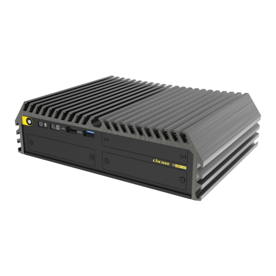
Page 13: Product Pictures
2 x Full-size Mini PCIe sockets for module expansion ⚫ Optional CMI/MEC modules for I/O expansion ⚫ Wide operating temperature: -40°C to 70°C ⚫ Military standard (MIL-STD-810G) shock & vibration proof ⚫ Railway EMC standard EN50155 (EN 50121-3-2 only) certified DV-1000 Series | User Manual... -
Page 14: Hardware Specification
• 1x DisplayPort Connector (4096 x 2304@60Hz) • 1x VGA Connector (1920 x 1200 @60Hz) Audio Audio Codec • Realtek® ALC888, High Definition Audio Line-out • 1x Line-out, Phone Jack 3.5mm Mic-in • 1x Mic-in, Phone Jack 3.5mm DV-1000 Series | User Manual... - Page 15 12V/24V (With Optional CFM Module) Clear CMOS Switch • 1x Clear CMOS Switch Reset Button • 1x Reset Button Instant Reboot • Support 0.2sec Instant Reboot Technology Watchdog Timer • Software Programmable Supports 256 Levels System Reset DV-1000 Series | User Manual...
- Page 16 CMOS Battery Backup • SuperCap Integrated for CMOS Battery Maintenance-free Operation • MTBF: 458,722 hours MTBF - Database: Telcordia SR-332 Issue3, Method 1, Case 3 Operating System Windows • Windows® 10 Linux • Supports by project DV-1000 Series | User Manual...
- Page 17 • CE, FCC, ICES-003 Class A, EN50121-3-2 (Railway), E-mark Safety • IEC/EN 62368-1 * Product Specifications and features are for reference only and are subject to change without prior notice. For more information, please refer to the latest product datasheet from Cincoze's website. DV-1000 Series | User Manual...
-
Page 18: System I/O
Used to insert a SIM card Reset Used to connect USB 2.0/1.1 device USB 3.2 GEN1 Used to reset the system Used to connect USB 3.2 GEN1/3.0/2.0/1.1 AT/ATX device Used to select AT or ATX power mode DV-1000 Series | User Manual... - Page 19 Used to connect a monitor with VGA Used to connect USB 3.2 GEN1/3.0/2.0/1.1 interface device Used to connect a monitor with DisplayPort Used to connect to local area network interface Used to connect to RS-232/422/485 serial devices DV-1000 Series | User Manual...
-
Page 20: Mechanical Dimension
1.7 Mechanical Dimension Unit: mm DV-1000 Series | User Manual... -
Page 21: Chapter 2 Switches & Connectors
Chapter 2 Switches & Connectors DV-1000 Series | User Manual... -
Page 22: Location Of Switches And Connectors
2.1 Location of Switches and Connectors 2.1.1 Top View 2.1.2 Bottom View DV-1000 Series | User Manual... -
Page 23: Switches And Connectors Definition
IGN Module Timing Setting Switch (only functional with IGN module) bottom view Location Definition AT_ATX1 AT / ATX Power Mode Switch COM1~2 Power Select Switch Super CAP Switch 24V_12V_1 IGN Module Voltage Mode Setting Switch Reset1 Reset Button CLR_CMOS1 Clear BIOS Switch DV-1000 Series | User Manual... - Page 24 IGN connector mini PCIE card connector (support mPCIE, mSATA interface) mini PCIE card connector (support mPCIE, mSATA, USB3 interface) DP_B1 DDI Signal connector support DP/HDMI (2K) interface BTB_FH1/BTB_FH2 DIO or COM Port Board to Board Connector DV-1000 Series | User Manual...
-
Page 25: Switches Definition
COM1 / 2 Voltage Function Setting via DIP Switch Location Function DIP1 DIP2 0V(RI) ON (Default) ON (Default) COM1 Location Function DIP3 DIP4 0V(RI) ON (Default) ON (Default) COM2 SW3: Super CAP Switch Function Super CAP Enable (Default) Disable DV-1000 Series | User Manual... - Page 26 Reset1: System Reset Button Button Definition Button Definition Push Reset System Push Reset System CLR_CMOS1: Clear CMOS Switch Definition 1-2 (Left) Normal Status (Default) 2-3 (Right) Clear CMOS DV-1000 Series | User Manual...
-
Page 27: Definition Of Connectors
46 NA 11 REFCLK- 47 NA 12 NA SMB_CLK 48 +1.5V 13 REFCLK+ PETN/SATATN 49 NA 14 NA SMB_DATA 50 GND 15 GND PETP/SATATP 51 NA 16 NA 52 +3.3V 17 NA 18 GND USB_D- DV-1000 Series | User Manual... - Page 28 48 +1.5V PETN/SATATN/ 13 REFCLK+/SIM_PWR2 31 49 NA USB3TN 14 SIM_Reset1 32 SMB_DATA 50 GND PETP/SATAP/ 15 GND 51 NA USB3TP 16 SIM_VPP1 34 GND 52 +3.3V 17 SIM_CLK2 35 GND 18 GND 36 USB_D- DV-1000 Series | User Manual...
- Page 29 W_DISABLE1# +3.3V (Pull-up) USB_D- UARTX/RGI_DT I2C_DATA WTD1N/PETP1 PCM_CLK UART_CTS/RGI_RSP I2C_CLK PETP0 WTD1P/PETN1 PCM_SYNC/LPC_RST UART_RTS/BRI_DT PETN0 PMC_IN WTD0N/PETP1 USB3_TX4- PERST1# PERP0 WTD0P/PERN1 USB3_TX4+ CLKREQ1# PERN0 PEWAKE1# WTCLKN/REFCLKP1 UART_WAKE# +3.3V REFCLKP0 WTCLKP/REFCLKN1 UART_RX/BRI_RSP +3.3V REFCLKN0 SUSCLK PERST0# DV-1000 Series | User Manual...
- Page 30 PEWAKE# PERN1 REFCLKP +3.3V PERN3 PERP1 PERP3 PETN1 PETN3 PETP1 +3.3V DEVSLP PETP3 +3.3V SMB_CLK PERN0/SATARP0 +3.3V SMD_DATA SUSCLK PERN2 PERP0/SATARN0 PEDET +3.3V ALERT# +3.3V PERP2 +3.3V CFG0 PETN0/SATATN0 +3.3V PETN2 PETP0/SATATP0 CFG2 RESET# PETP2 DV-1000 Series | User Manual...
- Page 31 CN1 / CN2: LAN1 / 2 LED Status Definition Act LED Status Definition Blinking Yellow Data Activity Steady Yellow No Activity Link LED Status Definition Steady Green 1Gbps Network Link Steady Orange 100Mbps Network Link 10Mbps Network Link DV-1000 Series | User Manual...
- Page 32 Connector Type: Terminal Block 2X2 4-pin, 3.5mm pitch Definition PWR_SW Do not apply power to this connector! This port is used to connect a SWITCH! FAN1: Smart Fan Connector Connector Type: Terminal Block 1X4 4-pin, 3.5mm pitch Definition +12V SENSE Control DV-1000 Series | User Manual...
- Page 33 Connector Type: 1x4 4-pin Wafer, 2.0mm pitch Pin 1 Definition +12V COM1 / COM2: RS232 / RS422 / RS485 Connector Connector Type: 9-pin D-Sub RS422 / 485 RS485 RS232 Full Duplex Half Duplex Definition Definition Definition DATA - DATA + DV-1000 Series | User Manual...
-
Page 34: Chapter 3 System Setup
Chapter 3 System Setup DV-1000 Series | User Manual... -
Page 35: Removing The Top Cover
1. Turn over the unit to have the bottom side face up, loosen the 6 screws on the bottom cover and place them aside for later use. 2. Remove the bottom cover from the chassis and place it aside. DV-1000 Series | User Manual... - Page 36 3. Loosen the indicated 2 screws and remove the HDD bracket. 4. Loosen the indicated 5 screws 5. Hold front and rear panel and lift up the body of unit vertically. DV-1000 Series | User Manual...
- Page 37 6. Turn over the body of the unit and place it gently. If the thermal pads are attached onto the top cover after disassembly, please paste the thermal pads back to mainboard as marked in the photo. DV-1000 Series | User Manual...
-
Page 38: Installing The Cpu
Place the protection cover back and fasten the two screws as indicated. This holder needs a total of four screws to complete the locking. For the locking steps of the other two, please refer to the chapter of Installing Top Cover. DV-1000 Series | User Manual... - Page 39 Place the thermal pad on the CPU. Make sure the protective film on the Thermal Pad has been removed before assembling the unit back to the cover! DV-1000 Series | User Manual...
-
Page 40: Installing So-Dimm
1. Locate the SODIMM socket on the top side of system. 2. Insert a SO-DIMM at a 45-degree angle until its edge connector is connected to SO-DIMM socket firmly. 45° 3. Press down the module until the retaining clips snap back in place. DV-1000 Series | User Manual... -
Page 41: Installing A Mini-Pcie/Msata Card
Insert a Mini-PCIe or mSATA card at a 45-degree angle until its edge connector is connected firmly into slot. For 3G/4G Mini-PCIe card, please install onto CN6 slot. 45° Press the card down and secure it with 2 screws. DV-1000 Series | User Manual... -
Page 42: Installing M.2 E Key Card
2. Tilt the M.2 E Key card at a 45-degree angle and insert it to the socket until the golden finger connector of the card seated firmly. 45° 3. Press the card down and secure it with 1 screw. DV-1000 Series | User Manual... -
Page 43: Installing M.2 M Key Card
2. Tilt the M.2 M Key card at a 45-degree angle and insert it to the socket until the golden finger connector of the card seated firmly. 45° 3. Press the card down and secure it with the screw. DV-1000 Series | User Manual... -
Page 44: Installing Antennas
Please install a Mini PCIe wireless LAN card at MINIPCIE socket before antenna installation. 1. Remove the antenna plug on the rear panel. 2. Penetrate the antenna jack through the hole. 3. Put on the washer and fasten the nut of antenna jack. DV-1000 Series | User Manual... - Page 45 4. Assemble the antenna and antenna jack together. 5. Attach the RF connector of the cable’s another end onto the card. DV-1000 Series | User Manual...
-
Page 46: Installing Top Cover
3.8 Installing Top Cover 1. Hold front and rear panel and put the body of unit back to chassis. 2. Fasten the indicated 7 screws 3.9 Installing SATA Hard Drive 1. Locate the HDD slot. DV-1000 Series | User Manual... - Page 47 4 provided screws to assemble HDD and HDD bracket together. 3. Insert the HDD bracket and push it until the HDD connector is fully inserted into the SATA slot. 4. Fix the HDD bracket by fastening the two screws. DV-1000 Series | User Manual...
-
Page 48: Installing Bottom Cover
3.10 Installing Bottom Cover 1. Place the bottom cover back to system and fasten it with the 6 screws. 3.11 Removing the Front Cover Plate 1. Loosen the 2 screws on the front cover plate and remove it. DV-1000 Series | User Manual... -
Page 49: Installing A Sim Card
3.12 Installing a SIM Card 1. Locate the SIM card slot at front side. 2. Insert a SIM card into SIM slot with the gold contacts facing up. Please pay attention to the insert orientation as illustrated. DV-1000 Series | User Manual... -
Page 50: Replacing The Cmos Battery
This chapter is to introduce how to replace the CMOS battery when it is dead. 1. Locate the removable CMOS Battery and loosen the screw. 2. Pull out the CMOS battery bracket. 3. Loosen the screw. DV-1000 Series | User Manual... - Page 51 4. Pull down the indicated portion and replace the CMOS battery with a new one. (please note the battery’s positive/negative pole orientation when you execute this step). Battery’s negative pole side 5. Fasten the screw back. 6. Insert the CMOS battery bracket. DV-1000 Series | User Manual...
-
Page 52: Fastening The Cover
7. Fasten the screw back. 3.14 Fastening the Cover 1. Fasten the cover by using the two screws. DV-1000 Series | User Manual... -
Page 53: Wall Mount Brackets
1. The mounting holes are at the bottom side of system. Use provided 8 screws to fasten the bracket on each side. 2. There are 2 mounting holes at each wall mount bracket for user to fix the system onto the wall. DV-1000 Series | User Manual... -
Page 54: Vesa Mount
1. The following picture illustrates the installation of the system on a VESA stand. Align the 4 screw holes of VESA stand with the screw holes on bottom side of system. Fasten the 4 screws to fix it. DV-1000 Series | User Manual... - Page 55 2. Provided below is the completion of mounting with the VESA stand. DV-1000 Series | User Manual...
-
Page 56: Chapter 4 Bios Setup
Chapter 4 BIOS Setup DV-1000 Series | User Manual... -
Page 57: Bios Introduction
You can use arrow keys ( ↑↓ ) to highlight the field and press <Enter> to call up the sub-menu. Then you can use the control keys to enter values and move from field to field within a sub-menu. If you want to return to the main menu, just press the <Esc >. DV-1000 Series | User Manual... -
Page 58: Main Setup
Use arrow keys to move among the items and press <Enter> to accept or enter a sub-menu. 4.2.1 System Date Set the date. Please use <Tab> to switch between date elements. 4.2.2 System Time Set the time. Please use <Tab> to switch between time elements. DV-1000 Series | User Manual... -
Page 59: Advanced Setup
With virtualization, one computer system can function as multiple virtual systems. ■ Active Process Cores Allows you to choose the number of active processor cores. Configuration options: [All] [1] [2] [3] [4] [5]. DV-1000 Series | User Manual... -
Page 60: Power & Performance
■ SATA Controller(s) [Enabled] Enables or disables SATA device. ■ SATA Mode Selection [AHCI] Allows you to select which mode SATA controller will operates. Configuration options: [AHCI], [RAID] ❑ Serial ATA Port 0 Port 0 [Enabled] DV-1000 Series | User Manual... -
Page 61: Pch-Fw Configuration
❑ Serial ATA Port 3 Port 1 [Enabled] Enables or disables SATA Port 3. PCH-FW Configuration 4.3.4 ■ Firmware Update Configuration Configure Management Engine Parameters ❑ Me FW Image Re-Flash [Disabled] Enables or disables ME firmware Image Re-Flash function. DV-1000 Series | User Manual... -
Page 62: Trusted Computing Settings
Enables or disables Storage Hierarchy function. ■ Endorsement Hierarchy [Enabled] Enables or disables Endorsement Hierarchy function. ■ Physical Presence Spec Version [1.3] Allows you to select which mode Physical Presence Spec Version will operate. Configuration options: [1.2], [1.3] DV-1000 Series | User Manual... -
Page 63: Acpi Settings
[S3 (suspend to RAM)]: Enables suspend to RAM state. F81866 Super IO Configuration 4.3.7 Set Parameters of Serial Ports. User can Enable/Disable the serial port and Select an optimal setting for the Super IO Device. DV-1000 Series | User Manual... - Page 64 Enables or disables watch dog function. ■ Watch Dog Mode [Sec] Allows to set watchdog timer unit <Sec> or <Min>. ■ Watch Dog Timer [0] Allows you to set watchdog timer’s value in the range of 0 to 255. DV-1000 Series | User Manual...
-
Page 65: Hardware Monitor
Configure External Smart Fan Parameters. ❑ Smart Fan Mode [Auto] Allows you to select Smart Fan Mode. Configuration options: [Auto] [Manual] ❑ Fan Speed Mode [RPM] Allows you to select Fan Speed Mode. Configuration options: [RPM] [Duty] DV-1000 Series | User Manual... -
Page 66: S5 Rtc Wake Settings
Enables or disables wake system from S5 (soft-off state). [Disabled]: Disables wake system from S5. [Fixed Time]: Sets a fixed time (HH:MM:SS) to wake system from S5. [Dynamic Time]: Sets an increase minute(s) from current time to wake system from S5. DV-1000 Series | User Manual... -
Page 67: Serial Port Console Redirection
Serial Port Console Redirection 4.3.10 ■ Console Redirection Allow users to enable or disable COM0, COM1 console redirection function. COM0 = Serial Port 1 COM1 = Serial Port 2 USB Configuration 4.3.11 DV-1000 Series | User Manual... -
Page 68: Network Stack Configuration
XHCI hand-off support. ■ USB Mass Storage Driver Support [Enabled] Enables or disables USB mass storage driver support. Network Stack Configuration 4.3.12 ■ Network Stack [Disabled] Enables or disables UEFI Network Stack. DV-1000 Series | User Manual... -
Page 69: Csm Configuration
[Legacy]: Enables legacy option ROM only. ■ Video [Legacy] Controls the execution of UEFI and Legacy Video option ROM. [Do not launch]: Disables option ROM execution. [UEFI]: Enables UEFI option ROM only. [Legacy]: Enables legacy option ROM only. DV-1000 Series | User Manual... -
Page 70: Nvme Configuration
The screen allows users to select options for the NVMe configuration, and change the value of the selected option. The options will show as the NVME Device is found. 4.4 Chipset Setup This section allows you to configure chipset related settings according to user’s preference. DV-1000 Series | User Manual... -
Page 71: System Agent (Sa) Configuration
■ Graphics Configuration ❑ Internal Graphics [Auto] Allows users to enable or disable Internal Graphics. Configuration options: [Auto] [Disabled] [Enabled] ■ VT-d [Enabled] Enables or disables Intel® Virtualization Technology for Directed I/O (VT-d) capability. 4.4.2 PCH-IO Configuration DV-1000 Series | User Manual... - Page 72 ❑ HD Audio [Enabled] Enables or disables HD Audio. ■ LAN i219V Controller [Enabled] Enables or disables I219 LAN Controller. ■ Wake on LAN (i219) [Enabled] Enables or disables integrated LAN Wake On LAN function. DV-1000 Series | User Manual...
- Page 73 Allows you to specify which power state system will enter when power is resumed after a power failure (G3 state). [Always on]: Enters to power on state. [Always off]: Enters to power off state. [Keep last state]: Enters to the last power state before a power failure. DV-1000 Series | User Manual...
-
Page 74: Security Setup
This section allows users to configure BIOS security settings. 4.5.1 Administrator Password Administrator Password controls access to the BIOS Setup utility. 4.5.2 User Password User Password controls access to the system at boot and to the BIOS Setup utility. DV-1000 Series | User Manual... -
Page 75: Boot Setup
Allows you to enable or disable Fast Boot function. If enabled, system boots with initialization of a minimal set of devices required to launch active boot option. 4.6.5 Hard Drive BBS Priority Allows you to set the order of the legacy devices in this group. DV-1000 Series | User Manual... -
Page 76: Save & Exit
4.7.8 Save as User Defaults This item allows you to save the changes done so far as user defaults. 4.7.9 Restore User Defaults This item allows you to restore the user defaults to all the setup options. DV-1000 Series | User Manual... -
Page 77: Chapter 5 Product Application
Chapter 5 Product Application DV-1000 Series | User Manual... -
Page 78: Digital I/O (Dio) Application
(3) Exit the Extended Function Mode The configuration register is used to control the behavior of the corresponding devices. To configure the register, use the index port to select the index and then write data port to alter DV-1000 Series | User Manual... - Page 79 Following is an example to enable configuration and to disable configuration by using debug. -o 4e 87 -o 4e 87 (enable configuration) -o 4e aa (disable configuration) 5.1.1.4 Relative Registers To program the F81866A configuration registers, see the following configuration procedures. DV-1000 Series | User Manual...
- Page 80 DV-1000 Series | User Manual...
- Page 81 DV-1000 Series | User Manual...
- Page 82 DV-1000 Series | User Manual...
- Page 83 <Output/Input Mode Selection> // Set GP80 to GP87 output Mode WriteByte(AddrPort, 0x88) // Select configuration register 88h WriteByte(DataPort, 0xXF)) // Set (bit 0~7) = 1 to select GP 80 ~87 as Output mode. <Output Value> DV-1000 Series | User Manual...
- Page 84 // Select configuration register 82h ReadByte(DataPort, Value) // Read bit 0~7(0xFx)= GP70~77 as High <input Value> WriteByte(AddrPort, 0xC2) // Select configuration register C2h ReadByte(DataPort, Value) // Read bit 0~7(0xFx)= GP30~37 as High <Leave the Extended Function Mode> WriteByte(AddrPort, 0xAA) DV-1000 Series | User Manual...
- Page 85 WriteByte(AddrPort, 0xAA) 5.1.1.6 Change base address <Enter the Extended Function Mode> WriteByte(AddrPort, 0x87) WriteByte(AddrPort, 0x87) // Must write twice to enter Extended mode <Select Logic Device> WriteByte(AddrPort, 0x07) WriteByte(dataPort, 0x06) // Select logic device 06h DV-1000 Series | User Manual...
- Page 86 // Select configuration register 60h (High Byte address) WriteByte(DataPort, (0x0A)) WriteByte(AddrPort, 0x61) // Select configuration register 61h (Low Byte address) WriteByte(DataPort, (0x00)) <Leave the Extended Function Mode> WriteByte(AddrPort, 0xAA) Cincoze default GPIO Port base address is 0xA00h DV-1000 Series | User Manual...
- Page 87 = DI7 = DO7 (Base Base address address +3) +2) (0xA02) (0xA03) = DI8 = DO8 (Base Base address address +3) +2) (0xA02) (0xA03) = DI9 = DO9 (Base (Base address +9) address +10) (0xA09) (0xA10) DV-1000 Series | User Manual...
- Page 88 = DI14 = DO14 (Base Base address address +9) +10) (0xA10) (0xA09) = DI15 = DO15 (Base Base address address +9) +10) (0xA10) (0xA09) = DI16 = DO16 (Base Base address address +9) +10) (0xA10) (0xA09) DV-1000 Series | User Manual...
- Page 89 0xA02 Pin Definition DI16 DI15 DI14 DI13 DI12 DI11 DI10 Data Bits Digital Input I/O Port Address 0xA09 Pin Definition DO16 DO15 DO14 DO13 DO12 DO11 DO10 Data Bits Digital Output I/O Port Address 0xA010 DV-1000 Series | User Manual...
-
Page 90: Dio Hardware Specification
DO Signal have to pull up resistor to XCOM+ for external device, the resistance will affect the pull up current Signal High Level: Pull up resistor to XCOM+ Signal Low Level: = XCOM- Sink Current: 1A (Max) DV-1000 Series | User Manual... -
Page 91: Dio Connector Definition
5.2.1 DIO Connector Definition BTB_FH1 DIO1 DIO2 Pin1 DIO1/DIO2: Digital Input / Output Connector Connector Type: Terminal Block 1X20 20-pin, 3.5mm pitch Pin Definition Definition XCOM+ XCOM+ (DC INPUT) (DC INPUT) XCOM- XCOM- (GND) (GND) DV-1000 Series | User Manual... - Page 92 BTB_FH2 DIO1 DIO2 Pin1 DIO1/DIO2: Digital Input / Output Connector Connector Type: Terminal Block 1X20 20-pin, 3.5mm pitch Pin Definition Definition XCOM+ XCOM+ (DC INPUT) (DC INPUT) XCOM- XCOM- (GND) (GND) DV-1000 Series | User Manual...
- Page 93 Definition XCOM+ XCOM+ XCOM+ XCOM+ (DC INPUT) (DC INPUT) (DC INPUT) (DC INPUT) DI10 DO10 DI11 DO11 DI12 DO12 DI13 DO13 DI14 DO14 DI15 DO15 DI16 DO16 XCOM- XCOM- XCOM- XCOM- (GND) (GND) (GND) (GND) DV-1000 Series | User Manual...
- Page 94 Reference Input Circuit Reference Output Circuit DV-1000 Series | User Manual...
-
Page 95: Gpio Led Application
0xAA to the index port. Following is examples to enable configuration and to disable configuration by using debug. Example to enable configuration: -o 4e 87 -o 4e 87 Example to disable configuration: -o 4e aa DV-1000 Series | User Manual... - Page 96 Relative Registers for GPIO LED ( GPIO10) Following example to set output enable for GPIO00 ( LED ON/OFF) by using debug. First step, read the original value from output enable register (index F0) -o 4e f0 -I 4f DV-1000 Series | User Manual...
- Page 97 01 . Second step: write the new value 01 to set bit0 for control output -o 4e f1 -o 4f 01 ( Note, the bit0 (GPIO00) can be set 0 or 1 ) DV-1000 Series | User Manual...
- Page 98 // Set (bit 0) =0 to output GPIO00 as Low WriteByte(AddrPort, 0xF1) // Select configuration register F1h WriteByte(DataPort, Value | 0x01 ) // Set (bit 0) =1 to output GPIO00 as High <Leave the Extended Function Mode> WriteByte(AddrPort, 0xAA) DV-1000 Series | User Manual...
- Page 99 5.3.1.5 Change base address Cincoze default GPIO Port base address is 0xA00 <Enter the Extended Function Mode> WriteByte(AddrPort, 0x87) WriteByte(AddrPort, 0x87) // Must write twice to enter Extended mode <Select Logic Device> WriteByte(AddrPort, 0x07) WriteByte(dataPort, 0x06) // Select logic device 06h...
-
Page 100: Gpio Led Status Definition
I/O Port data register address = Base address + 6 = 0xA06 = LED (Base address +6) (0xA06) 5.4 GPIO LED Status Definition GPIO LED LED Type Status LED Color GPIO activity Green GPIO LED No activity DV-1000 Series | User Manual... -
Page 101: Chapter 6 Optional Modules
Chapter 6 Optional Modules Pin Definitions and Settings DV-1000 Series | User Manual... -
Page 102: Optional Module Pin Definition & Settings
COM number is COM3~COM6 as shown below. DV-1000’s front bezel COM3~COM6: RS232 / RS422 / RS485 Connector Connector Type: 9-pin D-Sub RS422 / 485 RS485 RS232 Full Duplex Half Duplex Definition Definition Definition DATA - DATA + DV-1000 Series | User Manual... - Page 103 SW1: COM3~6 Power Select Location Function DIP1 DIP2 0V(RI) ON (Default) ON (Default) COM4/6 CMI-COM Module Location Function DIP3 DIP4 0V(RI) ON (Default) ON (Default) COM3/5 CMI-COM Module DV-1000 Series | User Manual...
-
Page 104: Cfm-Ign04-R10 Module
Default setting of Pin1 to Pin4 is OFF / OFF / OFF / OFF. 24V_12V_1: IGN Module Voltage Mode Setting Switch 12V / 24V Car Battery Switch Definition 12V Car Battery Input 24V Car Battery Input (Default) DV-1000 Series | User Manual... -
Page 105: Installing High Speed Cmi Module
When fixing the copper pillars, please be careful not to lock them too tightly so as not to damage the boss. It is recommended to use a 4kgf torque wrench to tighten the copper pillars. DV-1000 Series | User Manual... - Page 106 4. Insert the module vertically to the connector, and then fasten the 2 screws to fix it. 5. Attach on the CMI-DP01 bracket, and fasten the screws as indicated. DV-1000 Series | User Manual...
-
Page 107: Cmi-Hd03-R10/Ub1608-R10 Module
When fixing the copper pillars, please be careful not to lock them too tightly so as not to damage the boss. It is recommended to use a 4kgf torque wrench to tighten the copper pillars. DV-1000 Series | User Manual... - Page 108 4. Insert the module vertically to the connector, and then fasten the 2 screws to fix it. 5. Attach on the CMI-HD03 bracket, and fasten the screws as indicated. DV-1000 Series | User Manual...
-
Page 109: Installing Low Speed Cmi Module
When fixing the copper pillars, please be careful not to lock them too tightly so as not to damage the boss. It is recommended to use a 4kgf torque wrench to tighten the copper pillars. DV-1000 Series | User Manual... - Page 110 4. Insert the module vertically to the connector and fix it with the 2 screws. 5. Attach on the CMI-COM bracket. Fasten the 2 screws and 4 D-Sub jack screws to fix it. DV-1000 Series | User Manual...
-
Page 111: Cmi-Dio06-R10/Ub1618-R10
When fixing the copper pillars, please be careful not to lock them too tightly so as not to damage the boss. It is recommended to use a 4kgf torque wrench to tighten the copper pillars. DV-1000 Series | User Manual... - Page 112 4. Insert the module vertically to the connector and fix it with the 2 screws. 5. Attach on the CMI-DIO bracket and fasten the 2 screws to fix it. DV-1000 Series | User Manual...
-
Page 113: Installing Cfm Module
6.4 Installing CFM Module 6.4.1 CFM-IGN04-R10 1. Locate the IGN_PH1 connector. 2. Insert the module vertically to the connector 3. fasten the screw to fix it. DV-1000 Series | User Manual... -
Page 114: Installing Mec Module
3. Locate the Mini PCIe socket(s) on the top side of the system. MEC-USB module’s mPCIe card can only be installed onto connector CN6, then the USB board can be installed at bracket 1 or 2. DV-1000 Series | User Manual... - Page 115 4. Tilt the Mini PCIe card at a 45-degree angle and insert it to the socket until the golden finger connector of the card seated firmly. 45° 5. Press the card down and secure it with 2 screws. 6. Connect the attached wire to the USB board. DV-1000 Series | User Manual...
- Page 116 7. Connect the other end of the wire to the Mini PCIe card as indicated. 8. Attach the USB board onto the back side of the cover plate, and then fasten the two screws to secure the module. DV-1000 Series | User Manual...
-
Page 117: Mec-Lan-M102-15/Ub1611-R10
1. Loosen the 2 screws on the bracket 1 (left side) or bracket 2 (right side) and then remove 2. Attach the MEC-LAN bracket, and fasten the 2 screws to fix it as indicated. 3. Locate the Mini PCIe socket(s) on the bottom side of the system. DV-1000 Series | User Manual... - Page 118 4. Tilt the Mini PCIe card at a 45-degree angle and insert it to the socket until the golden finger connector of the card seated firmly. 45° 5. Press the card down and secure it with 2 screws. 6. Connect the attached wires to the LAN board. DV-1000 Series | User Manual...
- Page 119 7. Connect the wires to the Mini PCIe card as indicated. 8. Attach the LAN board onto the back side of the cover plate, and then fasten the two screws to secure the module. DV-1000 Series | User Manual...
-
Page 120: Installing Optional Accessories
6.6 Installing Optional Accessories 6.6.1 DINRAIL-R10 1. Prepare the DIN-RAIL Mount Kit. 2. The mounting holes are at the bottom of system. Fasten the 2 screws to fix the DIN-Rail mount bracket with system together. DV-1000 Series | User Manual... -
Page 121: Fan-Ex104
1. Prepare the external fan. Loosen the 2 screws halfway on mounting frame before attempting to install it. 2. Slide the FAN into the middle groove of chassis as illustrated. Tighten the 2 screws to fix it onto chassis. DV-1000 Series | User Manual... - Page 122 3. Move the fan to the center of chassis. Tighten the 2 screws marked on photo to secure it. 4. Connect the FAN cable to external fan power connector at rear panel. DV-1000 Series | User Manual...
- Page 123 © 2022 Cincoze Co., Ltd. All rights reserved. The Cincoze logo is a registered trademark of Cincoze Co., Ltd. All other logos appearing in this catalog are the intellectual property of the respective company, product, or organization associated with the logo.
Need help?
Do you have a question about the DV-1000 Series and is the answer not in the manual?
Questions and answers