
Related Manuals for Cincoze DC-1200 Series


Summary of Contents for Cincoze DC-1200 Series
- Page 1 Fanless Computing Solution Intel® Pentium® N4200 Processor Compact Fanless Embedded Computer DC-1200 Series...
-
Page 2: Table Of Contents
| User’s Manual DC-1200 Compact Size Fanless Computer Contents Prefaces Revision …………………………………………………..……………….………… 04 Copyright Notice ……………………………………………………………………. 04 Acknowledgement …..………………………………………………..... 04 Disclaimer …………………………………………………………………………… 04 Declaration of Conformity …………………………………………………………. 04 Product Warranty Statement ……………………………………………………… 05 Technical Support and Assistance ……………………………………………….. 06 Conventions Used in this Manual ………………………………………………… 06 Safety Precaution ……...……………………………………………………………... - Page 3 | User’s Manual DC-1200 Compact Size Fanless Computer Chapter 4 BIOS Setup 4.1 BIOS Introduction …….……….……….…….…….…..….…………... 42 4.2 Main Setup ……..……….…………….…….…..….………………..43 4.3 Advanced Setup ……………………….……….……………………….. 44 4.3.1 ACPI Settings ……..…………….……….………………………. 44 4.3.2 F81866 Super IO Configuration ..…….………………………... 45 4.3.3 Hardware Monitor ………………..……………………………..47 4.3.4 S5 RTC Wake Setting …….……..……………..……………..
-
Page 4: Revision
2019/02/01 Copyright Notice © 2017 by Cincoze Co., Ltd. All rights are reserved. No parts of this manual may be copied, modified, or reproduced in any form or by any means for commercial use without the prior written permission of Cincoze Co., Ltd. -
Page 5: Product Warranty Statement
(such as a fuse, battery, etc.), re not warranted. Before sending your product in, you will need to fill in Cincoze RMA Request Form and obtain a RMA number from us. Our staff is available at any time to provide you with the most friendly and immediate service. -
Page 6: Technical Support And Assistance
| User’s Manual DC-1200 Compact Size Fanless Computer Technical Support and Assistance 1. Visit the Cincoze website at www.cincoze.com where you can find the latest information about the product. 2. Contact your distributor or our technical support team or sales representative for technical support if you need additional assistance. -
Page 7: Safety Precaution
| User’s Manual DC-1200 Compact Size Fanless Computer Safety Precautions Before installing and using this device, please note the following precautions: 1. Read these safety instructions carefully. 2. Keep this User’s Manual for future reference. 3. Disconnected this equipment from any AC outlet before cleaning. 4. -
Page 8: Package Content
| User’s Manual DC-1200 Compact Size Fanless Computer Package Contents Before installation, please ensure all the items listed in the following table are included in the package. Q’ty Item Description DC-1200 Compact Size Fanless Embedded Computer Utility DVD Driver Thermal Pad (for CPU Thermal Block) Power Terminal Block Connector Screw Pack Remote Power On/Off Terminal Block Connector... -
Page 9: Optional Modules And Accessories
15/UB1111 Cutout for DC-1200 SIDE03 Side Mount Kit for DC-1200 Series, with KMRH-K175 for DIN-Rail option Adapter AC/DC 12V 5A 60W, GST60A12-CIN, wide temp(-30 ° C ~ +70 ° C) GST60A12-CIN Adapter AC/DC 24V 5A 120W, GST120A24-CIN, wide temp(-30 ° C ~ +70 ° C),... -
Page 10: Chapter 1 Product Introductions
Chapter 1 Product Introductions... -
Page 11: Overview
PCIe slot, dual SIM sockets, DVI-D, and DisplayPort. The system also provides 2.5" SATA drive bay and mSATA socket for extensive storage requirements. Furthermore, it is much easier to utilize Cincoze’ ready-to-use CMI& CFM modules for extension of digital I/O, serial ports, power ignition sensing, Power over Ethernet (PoE) even the third output of video for a variety of applications. -
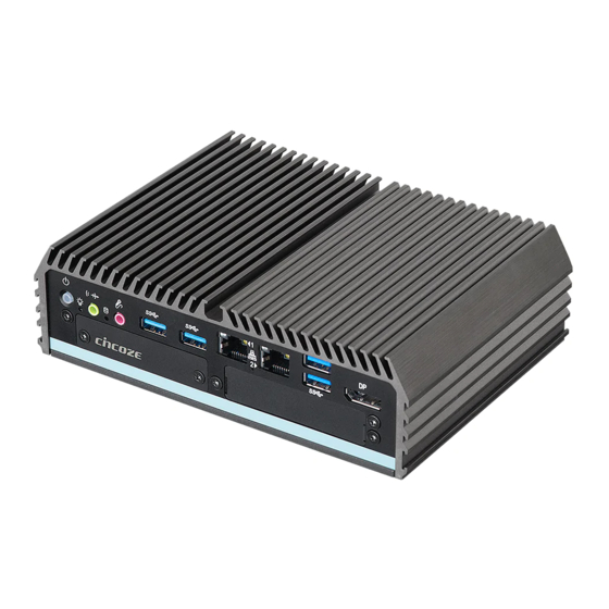
Page 12: Product Pictures
| User’s Manual DC-1200 Compact Size Fanless Computer 1.3 Product Pictures 1.4 Key Features • Onboard Intel ® ® Pentium N4200 Processor • Supports Triple Independent Display • Supports CMI Interface for I/O Expandability • Supports PoE+ and Power Ignition Function (with optional CFM modules) •... -
Page 13: Hardware Specification
| User’s Manual DC-1200 Compact Size Fanless Computer 1.5 Hardware Specification Processor Power Requirement • Onboard Intel • Supports AT/ATX Power Type ® ® Pentium N4200 Quad Core Processor, • Power Input Voltage 9~48VDC up to 2.50 GHz • 1x 3-pin Terminal Block •... -
Page 14: System I/O
| User’s Manual DC-1200 Compact Size Fanless Computer 1.6 System I/O 1.6.1 Front Panel ATX Power On/Off Switch DisplayPort Port Press to power-on or power-off the system Used to connect the system with DisplayPort monitor Universal I/O Bracket Power LED Used for customized I/O output with optional modules Indicates the power status of the system Reset Button... - Page 15 Universal I/O Brackets These expansion areas are reserved for Mini-PCIe expansion or Cincoze own pin- defined interfaces (CMI interfaces). CMI interfaces support various type of I/O modules such as COM / DIO / DVI / VGA / HDMI modules.
-
Page 16: Mechanical Dimension
| User’s Manual DC-1200 Compact Size Fanless Computer 1.7 Mechanical Dimensions Unit: mm... -
Page 17: Chapter 2 Switches And Connectors
Chapter 2 Switches and Connectors... -
Page 18: Jumper Settings
| User’s Manual DC-1200 Compact Size Fanless Computer 2.1 Jumpers Settings DC-1200 is featured with jumper-free design 2.2 Location of the Switches and Connectors 2.2.1 Top View... -
Page 19: Bottom View
| User’s Manual DC-1200 Compact Size Fanless Computer 2.2.2 Bottom View... -
Page 20: Switch And Connector Definition
| User’s Manual DC-1200 Compact Size Fanless Computer 2.3 Switches and Connectors Definition List of Switches Location Definition POWER_SW3 ATX Power on/off Button Super CAP Switch and COM1~2 Power Select Switch Reset1 Reset Button AT_ATX AT/ ATX Power Mode Switch CLR_CMOS1 Clear BIOS Switch IGN Module Timing Setting Switch... -
Page 21: Definition Of Switches
| User’s Manual DC-1200 Compact Size Fanless Computer 2.4 Definition of Switches PWR_SW3: System Power on/off Button Switch Definition Push Power on/off System RESET1 : Reset Button Switch Definition Push Reset System AT_ATX : AT / ATX Power Mode Switch Switch Definition 1-2 (Left) - Page 22 | User’s Manual DC-1200 Compact Size Fanless Computer PWR_SW_LED: LED of Temperature Status Temperature LED Color Status 0℃ ~ 60℃ Colorless 60℃ ~ 87℃ Blue Over 87℃ SW1: Super CAP Switch and COM1~2 with Power Select Switch Function Setting via DIP Switch Location Function DIP1...
-
Page 23: Definition Of Connectors
2.5 Definition of Connectors MINIPCIE1: Mini PCI-Express Socket (Support mPCIE & SIM Module) Definition Definition WAKE# 3.3Vaux +1.5V SMB_CLK PETn0 1.5V SMB_DATA UIM_RESET_B PETp0 UIM_PWR_A UIM_DATA_A USB_D- REFCLK- UIM_CLK_A USB_D+ +3.3Vaux REFCLK+ / UIM_PWR_B UIM_RESET_A +3.3Vaux UIM_VPP_A UIM_IC_DM / (UIM_CLK_B) UIM_IC_DP / (UIM_DATA_B) W_DISABLE1# PERST#... - Page 24 MINIPCIE2 : Mini PCI-Express Socket (Support mPCIE & mSATA) Definition Definition WAKE# 3.3V +1.5V SMB_CLK PETn0 / SATA_TXN 1.5V SMB_DATA PETp0 / SATA_TXP USB_D- REFCLK- USB_D+ +3.3Vaux REFCLK+ +3.3Vaux W_DISABLE1# PERST# +1.5V PERn0 / SATA_RXP +3.3Vaux PERp0 / SATA_RXN +3.3Vaux...
- Page 25 | User’s Manual DC-1200 Compact Size Fanless Computer PWR_SW2 : Remote Power On/Off Connector Definition PWR_SW (Note: Please do not apply power to the pins. This port is used to connect a switch.) DC_IN1 : DC Power Input Connector (+9~48V) Connector Type: Terminal Block 1X3 3-pin, 5.0mm pitch Definition +9~48V IN...
- Page 26 | User’s Manual DC-1200 Compact Size Fanless Computer COM1_1 / COM2_1 : RS232 / RS422 / RS485 Connector Connector Type: 9-pin D-Sub RS422 / 485 Full RS485 Half RS232 Definition Duplex Definition Duplex Definition DATA - DATA + POWER1, POWER2 : Power Connector Connector Type: 1x4 4-pin Wafer, 2.0mm pitch Definition Pin 1...
-
Page 27: Chapter 3 System Setup
Chapter 3 System Setup... -
Page 28: Removing The Chassis Bottom Cover
| User’s Manual DC-1200 Compact Size Fanless Computer 3.1 Removing the Chassis Bottom Cover In order to prevent electric shock or system damage, before removing the chassis cover, must turn off power and disconnect the unit from power source. 1. Turn over the unit to have the bottom side face up, loosen the 4 screws of bottom cover and place them aside. -
Page 29: Removing The Chassis
| User’s Manual DC-1200 Compact Size Fanless Computer 3.2 Removing the Chassis 1. Hold front and rear panel and lift up the body of unit vertically. 2. Turn over the body of the unit and place it gently. -
Page 30: Installing Antennas
| User’s Manual DC-1200 Compact Size Fanless Computer 3.3 Installing Antennas 1. Remove the antenna hole covers at rear panel. 2. Have antenna jack penetrate through the hole. 3. Put on washer and fasten the nut with antenna jack. - Page 31 | User’s Manual DC-1200 Compact Size Fanless Computer 4. Assemble the antenna and antenna jack together. 5. Attach the RF connector at another end of cable onto the module.
-
Page 32: Installing Full-Size Mini Pcie Cards On Bottom Side
| User’s Manual DC-1200 Compact Size Fanless Computer 3.4 Installing Full-Size Mini PCIe Cards on Bottom Side (including Half-Size Mini PCIe card) 1. Turn over the body of unit. Unscrew the 3 screws on HDD bracket and remove the bracket. 2. - Page 33 | User’s Manual DC-1200 Compact Size Fanless Computer 3. Tilt the Mini PCIe modules at 45 degrees angle and insert it to the slot until the gold- pated connector of module contacted firmly with the slot. 45° 45° 4. Press down the module and use two screws to fix a module. 5.
-
Page 34: Installing A Sata Hard Drive
| User’s Manual DC-1200 Compact Size Fanless Computer 3.5 Installing a SATA Hard Drive 1. Lift up the empty HDD bracket by unscrewing the 3 screws. 2. Make the PCB side of the HDD face up, place the HDD bracket on it. Ensure the direction of bracket is correct and use 4 provided screws to assemble HDD and HDD bracket together. -
Page 35: Installing A Sodimm
| User’s Manual DC-1200 Compact Size Fanless Computer 3.6 Installing a SODIMM 1. Locate SODIMM socket. 2. Tilt the SODIMM module at a 45 degree angle and insert it to SODIMM socket until the gold-pated connector of module contacted firmly with the socket. 45°... -
Page 36: Installing The Chassis
| User’s Manual DC-1200 Compact Size Fanless Computer 3.7 Installing the Chassis 1. Hold the body of unit, and make sure the both sides of front and rear panels are in the chassis grooves and insert the body of unit into chassis. -
Page 37: Installing The Chassis Bottom Cover
| User’s Manual DC-1200 Compact Size Fanless Computer 3.8 Installing the Chassis Bottom Cover 1. Level the grooves on the cover at front and rear panels. Put on the cover. 2. Fasten the 4 screws to fix the cover. -
Page 38: Installing A Sim Card
| User’s Manual DC-1200 Compact Size Fanless Computer 3.9 Installing a SIM Card 1. Loosen 2 screws on the front panel to remove the cover plate. 2. SIM card slots are at the front panel of the system. 3. Insert the SIM card. -
Page 39: Installing Wall Mount Brackets
| User’s Manual DC-1200 Compact Size Fanless Computer 3.10 Installing Wall Mount Brackets DC-1200 offers Wall Mount that customers can install system on the wall in convenient and economical way. 1. The mounting holes are at the bottom side of system. Use provided 4 screws to fasten the bracket with each side on system together. -
Page 40: Installing Din-Rail Mount Clips
DC-1200 Compact Size Fanless Computer 3.11 Installing DIN-Rail Mount Clips DC-1200 series offers DIN-Rail Mount that customer can install system on the DIN Rail. 1. Please refer to section 3.10 Wall Mount Brackets to install mounting bracket at both sides of system. -
Page 41: Chapter 4 Bios Setup
Chapter 4 BIOS Setup... -
Page 42: Bios Introduction
| User’s Manual DC-1200 Compact Size Fanless Computer 4.1 BIOS Introduction The BIOS (Basic Input/Output System) is a program located on a Flash Memory on the motherboard. When you start the computer, the BIOS program will gain control. The BIOS first operates an auto-diagnostic test called POST (power on self test) for all the necessary hardware, it detects the entire hardware device and configures the parameters of the hardware synchronization. -
Page 43: Main Setup
| User’s Manual DC-1200 Compact Size Fanless Computer 4.2 Main Setup Press <Del> key to enter BIOS CMOS Setup Utility, the Main Menu (as shown below) will appears on the screen. Use arrow keys to move among the items and press <Enter> to accept or enter a sub-menu. -
Page 44: Advanced Setup
| User’s Manual DC-1200 Compact Size Fanless Computer 4.3 Advanced Setup This section allows you to configure and improve your system and allows you to set up some system features according to your preference. 4.3.1 ACPI Settings... -
Page 45: F81866 Super Io Configuration
| User’s Manual DC-1200 Compact Size Fanless Computer ■ Enable ACPI Auto Configuration [Disabled] Enables or disables BIOS Advanced Configuration Power Interface® (ACPI) auto configuration. ■ Enable Hibernation [Enabled] Enables or disables system ability to hibernate state (OS/S4 state). This option may not be effective with some OS. - Page 46 | User’s Manual DC-1200 Compact Size Fanless Computer ■ Serial Port 1~6 Configuration ❑ Serial Port [Enabled] Enables or disables serial port. ❑ Change Settings [Auto] Allows you to change the IO Address & IRQ settings of the specified serial port. ❑...
-
Page 47: Hardware Monitor
| User’s Manual DC-1200 Compact Size Fanless Computer 4.3.3 Hardware Monitor This screen displays the current status of all monitored hardware devices/components such as voltages, temperatures. 4.3.4 S5 RTC Wake Settings... -
Page 48: Serial Port Console Redirection
| User’s Manual DC-1200 Compact Size Fanless Computer ■ Wake system from S5 [Disabled] Enables or disables wake system from S5 (soft-off state). [Disabled]: Disables wake system from S5. [Fixed Time]: Sets a fixed time (HH:MM:SS) to wake system from S5. [Dynamic Time]: Sets a increase minute(s) from current time to wake system from 4.3.5 Serial Port Console Redirection ■... -
Page 49: Cpu Configuration
| User’s Manual DC-1200 Compact Size Fanless Computer 4.3.6 CPU Configuration ■ Socket 0 CPU Information This section provides information on your CPU, frequency, and cache memory. ■ Active Processor Cores [Enabled] Number of cores to enable in each processor package. ■... -
Page 50: Network Stack Configuration
| User’s Manual DC-1200 Compact Size Fanless Computer 4.3.7 Network Stack Configuration ■ Network Stack [Disabled] Enables or disables UEFI Network Stack. 4.3.8 CSM Configuration This option controls legacy/UEFI ROMs priority. - Page 51 | User’s Manual DC-1200 Compact Size Fanless Computer ■ CSM Support [Disabled] Enables or disables compatibility support module. ■ Boot option filter [UEFI and Legacy] Allows you to select which type of operating system to boot. [UEFI and Legacy]: Allows booting from operating systems that support legacy option ROM or UEFI option ROM.
-
Page 52: Usb Configuration
| User’s Manual DC-1200 Compact Size Fanless Computer 4.3.9 USB Configuration ■ Legacy USB Support [Enabled] This item allows you to enable or disable legacy USB support. When set to [Auto], legacy USB support will be disabled automatically if no USB devices are connected. ■... -
Page 53: Chipset Setup
| User’s Manual DC-1200 Compact Size Fanless Computer 4.4 Chipset Setup This section allows you to configure chipset related settings according to user’s preference. 4.4.1 North Bridge This section provides information on the installed memory size. -
Page 54: South Bridge
| User’s Manual DC-1200 Compact Size Fanless Computer 4.4.2 South Bridge ■ OS Selection [Windows] Allows you to configure Operating System version to install. Configuration options: [Windows] [Intel Linux] ■ Mini PCIE1/USB3 Function Switch [Mini PCIE] Allows you to change Mini PCIE1 to [Mini PCIE] or [USB3]. ■... -
Page 55: South Cluster Configuration
| User’s Manual DC-1200 Compact Size Fanless Computer 4.4.3 South Cluster Configuration ■ PCI Express Configuration... - Page 56 | User’s Manual DC-1200 Compact Size Fanless Computer PCI Express Root Port 5 (MiniPcie2) ❑ PCI Express Root Port 5 (MiniPcie2) [Enabled] Enables or disables PCI Express Root Port. ❑ PCIeSpeed [Auto] Allows you to select PCI Express port speed. Configuration options: [Auto] [Gen1] [Gen2].
- Page 57 | User’s Manual DC-1200 Compact Size Fanless Computer ■ Miscellaneous Configuration ❑ Restore AC Power Loss [Last state] Allows you to specify which power state system will enter when power is resumed after a power failure (G3 state). [Always on]: Enters to power on state. [Always off]: Enters to power off state.
-
Page 58: Security Setup
| User’s Manual DC-1200 Compact Size Fanless Computer 4.5 Security Setup This section allows you to configure BIOS security settings. ■ Administrator Password Allows you to set Administrator Password to control access to the BIOS Setup utility. ■ User Password Allows you to set User Password to control access to the system at boot and to the BIOS Setup utility. -
Page 59: Boot Setup
| User’s Manual DC-1200 Compact Size Fanless Computer 4.6 Boot Setup This section allows you to configure Boot settings. ■ Bootup NumLock State Allows you to set NumLock key to [On] or [Off] state when system boots up. ■ Quiet Boot Allows you to enable or disable Quiet Boot function. -
Page 60: Save & Exit
| User’s Manual DC-1200 Compact Size Fanless Computer 4.7 Save & Exit ■ Save Changes and Reset This item allows you to reset the system after saving changes. ■ Discard Changes and Reset This item allows you to reset system setup without saving any changes. ■... -
Page 61: Chapter 5 Product Application (For Cmi-Dio03 Only)
Chapter 5 Product Application (For CMI-DIO03 Only) -
Page 62: Digital I/O (Dio) Application
| User’s Manual DC-1200 Compact Size Fanless Computer This chapter describes the DIO applications. 5.1 Digital I/O (DIO) Application This section describes DIO application of the product. The content and application development are better understood and implemented by well experienced professionals or developers. 5.1.1 Digital I/O (DIO) Programming Guide 5.1.1.1 Pins for Digital I/O BTB_FH2... - Page 63 | User’s Manual DC-1200 Compact Size Fanless Computer 5.1.1.2 Programming Guide To program the F81866A configuration registers, the following configuration procedures must be followed in sequence: (1) Enter the Extended Function Mode (2) Configure the configuration registers (3) Exit the Extended Function Mode The configuration register is used to control the behavior of the corresponding devices.
- Page 64 | User’s Manual DC-1200 Compact Size Fanless Computer...
- Page 65 | User’s Manual DC-1200 Compact Size Fanless Computer...
- Page 66 | User’s Manual DC-1200 Compact Size Fanless Computer...
- Page 67 | User’s Manual DC-1200 Compact Size Fanless Computer 5.1.1.4 Sample Code in C Language 5.1.1.4.1 Control of GP70 to GP73 (DI1 ~ DI4) (BTB_FH1) #define AddrPort 0x4E #define DataPort 0x4F <Enter the Extended Function Mode> WriteByte(AddrPort, 0x87) WriteByte(AddrPort, 0x87) // Must write twice to entering Extended mode <Select Logic Device>...
- Page 68 | User’s Manual DC-1200 Compact Size Fanless Computer 5.1.1.4.3 Control of GP74 to GP77 (DI1 ~ DI4) (BTB_FH2) #define AddrPort 0x4E #define DataPort 0x4F <Enter the Extended Function Mode> WriteByte(AddrPort, 0x87) WriteByte(AddrPort, 0x87) // Must write twice to entering Extended mode <Select Logic Device>...
- Page 69 | User’s Manual DC-1200 Compact Size Fanless Computer 5.1.1.4.5 Control of GP70 to GP77 (DI1 ~ DI8) (BTB_FH1 & BTB_FH2) #define AddrPort 0x4E #define DataPort 0x4F <Enter the Extended Function Mode> WriteByte(AddrPort, 0x87) WriteByte(AddrPort, 0x87) // Must write twice to entering Extended mode <Select Logic Device>...
- Page 70 // Select configuration register 60h (High Byte address) WriteByte(DataPort, ( 0x0A)) WriteByte(AddrPort, 0x61) // Select configuration register 61h (Low Byte address) WriteByte(DataPort, ( 0x00)) <Leave the Extended Function Mode> WriteByte(AddrPort, 0xAA) Cincoze default DIO Port base address is set to 0x0A00h...
- Page 71 | User’s Manual DC-1200 Compact Size Fanless Computer 5.1.1.5 DATA Bit Table (DIO) 7 6 5 4 3 2 1 0 = DI1 0 0 0 0 0 0 0 1 Value (Base address + 3) (0xA03) 7 6 5 4 3 2 1 0 = DI2 0 0 0 0 0 0 1 0 Value...
- Page 72 | User’s Manual DC-1200 Compact Size Fanless Computer 7 6 5 4 3 2 1 0 = DO1 0 0 0 0 0 0 0 1 Value (Base address + 2) (0xA02) 7 6 5 4 3 2 1 0 = DO2 0 0 0 0 0 0 1 0 Value...
- Page 73 | User’s Manual DC-1200 Compact Size Fanless Computer 5.1.1.6 DIO I/O Port Address (Default Address 0xA00) Pin Definition Data Bits Digital Input I/O Port Address 0xA03 Pin Definition Data Bits Digital Output I/O Port Address 0xA02...
-
Page 74: Digital I/O (Dio) Hardware Specification
| User’s Manual DC-1200 Compact Size Fanless Computer 5.2 Digital I/O (DIO) Hardware Specification • XCOM+ / 2XCOM+ : Isolated power in V+ • XCOM- / 2XCOM- : Isolated power in V- • Isolated power in DC voltage : 9~30V •... -
Page 75: Dio Connector Definitions
| User’s Manual DC-1200 Compact Size Fanless Computer 5.2.1 Digital I/O DIO Connector Definitions 5.2.1.1 BTB_FH1 DIO1: Digital Input / Output Connector Connector Type: Terminal Block 2X5 10-pin, 3.5mm pitch Definition Definition XCOM+ Pin1 XCOM- 5.2.1.2 BTB_FH2 DIO1: Digital Input / Output Connector Connector Type: Terminal Block 2X5 10-pin, 3.5mm pitch Definition Definition... - Page 76 | User’s Manual DC-1200 Compact Size Fanless Computer 5.2.1.3 BTB_FH1 & BTB_FH2 Pin11 Pin1 DIO1: Digital Input / Output Connector Connector Type: Terminal Block 2X5 10-pin, 3.5mm pitch Definition Definition Definition Definition XCOM+ XCOM+ DO1 (DO5) DI1 (DI5) DO2 (DO6) DI2 (DI6) DO3 (DO7) DI3 (DI7)
- Page 77 | User’s Manual DC-1200 Compact Size Fanless Computer...
-
Page 78: Chapter 6 Optional Modules And Accessories
Chapter 6 Optional Modules and Accessories Pin Definitions and Settings... -
Page 79: Location Of The Connectors For Cmi Modules
| User’s Manual DC-1200 Compact Size Fanless Computer 6.1 Location of the Connectors for CMI Modules Model No. Description CMI Module with 1x DVI-D Connector for DC-1200,1x Universal CMI-DVI01/UB1107 Bracket with 1x DVI-D Cutout for DC-1200 CMI Module with 1x VGA Port for DC-1200, 1x Universal Bracket with CMI-VGA01/UB1116 1x VGA Cutout for DC-1200 CMI Module with 1x HDMI Port for DC-1200, 1x Universal Bracket with... - Page 80 | User’s Manual DC-1200 Compact Size Fanless Computer Model No. Description CMI Module with 2x RS232/422/485 (Support 5V/12V) for DC-1200, 1x CMI-COM03/UB1103 Universal Bracket with 2x DB9 Cutout for DC-1200 CMI Module with 8x Optical Isolated DIO (4 in/4 out) for DC-1200, 1x CMI-DIO03/UB1115 Universal Bracket with DIO Cutout for DC-1200 Locate the CMI Modules/ connectors on system motherboard as indicated.
-
Page 81: Location Of The Connector For Cfm-Ign Module
| User’s Manual DC-1200 Compact Size Fanless Computer 6.2 Location of the Connector for CFM-IGN Module Model No. Description CFM Module with Power Ignition Sensing Control Function, Select CFM-IGN02 12V/24V Locate the CFM-IGN Module’s connector on system motherboard as indicated. -
Page 82: Location Of The Connector For Cfm-Poe Module
| User’s Manual DC-1200 Compact Size Fanless Computer 6.3 Location of the Connector for CFM-PoE Module Model No. Description CFM-PoE02 CFM Module with PoE Control Function, Individual Port 25.5W Locate the CFM-PoE Module’s connector on system motherboard as indicated. -
Page 83: Cmi-Com Module Connector Definition And Settings
| User’s Manual DC-1200 Compact Size Fanless Computer 6.4 CMI-COM Module Connector Definition and Settings Model No. Description CMI Module with 2x RS232/422/485 (Support 5V/12V) for DC-1200,1x CMI-COM03/UB1103 Universal Bracket with 2x DB9 Cutout for DC-1200 COM3 / COM4 / COM5 / COM6: RS232 / RS422 / RS485 Connector Connector Type: 9-pin D-Sub COM3 / COM4 RS422 / 485... - Page 84 | User’s Manual DC-1200 Compact Size Fanless Computer SW1 on CMI-COM Module: COM5~6 with Power Select Switch Function Setting via DIP Switch Location Function DIP1 DIP2 0V(RI) ON (Default) ON (Default) SW1 on CMI-COM COM3_1 Module Location Function DIP3 DIP4 0V(RI) ON (Default) ON (Default)
-
Page 85: Cfm-Ign Module Switches Definition And Settings
| User’s Manual DC-1200 Compact Size Fanless Computer 6.5 CFM-IGN Module Switches Definition and Settings Model No. Description CFM Module with Power Ignition Sensing Control Function, Select CFM-IGN02 12V/24V SW2 on CFM-IGN Module: IGN Module Timing Setting Switch Set shutdown delay timer when ACC is turned off Pin 1 Definition Pin 1 Pin 2... -
Page 86: Installing A Cmi-Dvi Module
| User’s Manual DC-1200 Compact Size Fanless Computer 6.6 Installing a CMI-DVI Module 1. Unscrew 2 screws to remove bracket#3 from rear panel. 2. Assemble the CMI-DVI bracket and CMI-DVI module together with 2 D-Sub jack screws . 3. Align two holes on the CMI-DVI bracket with the holes on the rear panel. - Page 87 | User’s Manual DC-1200 Compact Size Fanless Computer 4. Push the connector pins on CMI-DVI module until the pins can be inserted completely to the female connector (BTB_FH1) on the system’s mainboard. 5. Make sure the hole on CMI-DVI module is aligned with the screw hole on the system’s mainboard, and fasten a screw to fix it.
-
Page 88: Installing A Cmi-Vga Module
| User’s Manual DC-1200 Compact Size Fanless Computer 6.7 Installing a CMI-VGA Module 1. Unscrew 2 screws to remove bracket#3 from rear panel. 2. Assemble the CMI-VGA bracket and CMI-DVI module together with 2 D-Sub jack screws . 3. Align two holes on the CMI-VGA bracket with the holes on the rear panel. - Page 89 | User’s Manual DC-1200 Compact Size Fanless Computer 4. Push the connector pins on CMI-VGA module until the pins can be inserted completely to the female connector (BTB_FH1) on the system’s mainboard. 5. Make sure the hole on CMI-VGA module is aligned with the screw hole on the system’s mainboard, and fasten a screw to fix it.
-
Page 90: Installing A Cmi-Hdmi Module
| User’s Manual DC-1200 Compact Size Fanless Computer 6.8 Installing a CMI-HDMI Module 1. Unscrew 2 screws to remove bracket#3 from rear panel. 2. Attach the CMI-HDMI bracket on the backside of system’s rear panel, and fasten it with two screws. - Page 91 | User’s Manual DC-1200 Compact Size Fanless Computer 4. Fasten a screw to fix the CMI-HDMI module. 5. Align the hole on CMI-HDMI module with the screw hole on the system’s mainboard module, and insert vertically to the female connector (BTB_FH1) on the system’s mainboard.
-
Page 92: Installing A Cmi-Com Module
| User’s Manual DC-1200 Compact Size Fanless Computer 6.9 Installing a CMI-COM Module 1. Unscrew 2 screws to remove bracket#2 or bracket#3 from rear panel. 2. Assemble the CMI-COM bracket and CMI-COM module together with 4 D-Sub jack screws 3. Align two holes on the CMI-COM bracket with the holes on the rear panel. - Page 93 | User’s Manual DC-1200 Compact Size Fanless Computer 4. Push the connector pins on CMI-COM module until the pins can be inserted completely to the female connector (BTB_FH2 or BTB_FH1) on the system’s mainboard. 5. Make sure the hole on CMI-COM module is aligned with the screw hole on the system’s mainboard, and fasten a screw to fix it.
-
Page 94: Installing A Cmi-Dio Module
| User’s Manual DC-1200 Compact Size Fanless Computer 6.10 Installing a CMI-DIO Module 1. Unscrew 2 screws to remove bracket#2 or bracket#3 from rear panel. 2. Attach the CMI-DIO bracket on the backside of system’s rear panel, and fasten it with two screws. - Page 95 | User’s Manual DC-1200 Compact Size Fanless Computer 4. Make sure the hole on CMI-DIO module is aligned with the screw hole on the system’s mainboard, and fasten a screw to fix it.
-
Page 96: Installing A Cfm-Ign Module
| User’s Manual DC-1200 Compact Size Fanless Computer 6.11 Installing a CFM-IGN Module 1. Locate the IGN connector on system motherboard as indicated in page 75, and insert the male connector of CFM-IGN module to the female connector on system’s mainboard. 2. -
Page 97: Installing A Cfm-Poe Module
| User’s Manual DC-1200 Compact Size Fanless Computer 6.12 Installing a CFM-PoE Module 1. Locate the PoE connector on system motherboard as indicated in page 76, and insert the female connector of CFM-PoE module to the male connector on system’s mainboard. 2. - Page 98 | User’s Manual DC-1200 Compact Size Fanless Computer 4. Paste the thermal pads onto the heatsink and coil carefully.
-
Page 99: Installing A Side Mount Bracket
DC-1200 Compact Size Fanless Computer 6.13 Installing a Side Mount Bracket Model No. Description Side Mount Kit for DC-1200 Series, with KMRH-K175 for DIN-Rail SIDE03 option DC-1200 offers Side Mount that customer can install the system onto the right or left side of wall to create effectiveness of space. - Page 100 | User’s Manual DC-1200 Compact Size Fanless Computer 3. Place the side mount bracket on the bottom of system as shown in the picture below, and fasten the rest of 4 screws to fix the side mount bracket with system together. 4.
-
Page 101: Installing A Vesa Mount Bracket
| User’s Manual DC-1200 Compact Size Fanless Computer 6.14 Installing a VESA Mount Bracket DC-1200 offers VESA Mount that customer can mount system with VESA standards of 75 mm and 100 mm for various usages. 1. Provided below is the base of the system unit with screw holes specified to be Blue circles represent the use for VESA 75 mm. - Page 102 | User’s Manual DC-1200 Compact Size Fanless Computer 3. Provided below is completion of mounting with VESA stand.
- Page 103 © 2014 Cincoze Co., Ltd. All rights reserved. The Cincoze logo is a registered trademark of Cincoze Co., Ltd. All other logos appearing in this catalog are the intellectual property of the respective company, product, or organization associated with the logo.
Need help?
Do you have a question about the DC-1200 Series and is the answer not in the manual?
Questions and answers