
Related Manuals for Cincoze DX-1000-R10


Summary of Contents for Cincoze DX-1000-R10
- Page 1 Rugged Workstation 7/6th Generation Intel® Xeon® and Core™ Processors, Extreme Performance, Compact and Modular Rugged Workstation DX-1000 Series CN-TB-QP22-44_V1.0 DOC No: DX-1000 _R1.01_20171019001...
-
Page 2: Table Of Contents
| User’s Manual DX-1000 Series Rugged Workstation Contents Preface Revision …………………………………………….……..……………………..……….. 04 Copyright Notice …………………………………………………………………..……… 04 Acknowledgement …………………………………………….……………....04 Disclaimer ………………………………………………………….……………….…….. 04 Declaration of Conformity ……………………………………….……………….……… 04 Product Warranty Statement ………………………………………. …………….…….. 05 Technical Support and Assistance …………………………………. …………….……. 06 Conventions Used in this Manual ………………………………………….…….…….. - Page 3 | User’s Manual DX-1000 Series Rugged Workstation Chapter 4 BIOS Setup BIOS Introduction ………..…………………..……..………………………… 70 Main Setup………..…………………..……..……………………………….… 71 4.2.1 System Date ………..…………………..……..………………………. 71 4.2.2 System Time ………..…………………..……..………………………. 71 Advanced Setup ………..…………………..……..…………………….…….. 72 4.3.1 CPU Configuration..…………………………….………….…………… 72 4.3.2 SATA And RST Configuration..…………………………….…………… 73 4.3.3 PCH-FW Configuration..…………………………….…………………..
-
Page 4: Revision
2017/10/16 Copyright Notice © 2017 by Cincoze Co., Ltd. All rights are reserved. No parts of this manual may be copied, modified, or reproduced in any form or by any means for commercial use without the prior written permission of Cincoze Co., Ltd. -
Page 5: Product Warranty Statement
(such as a fuse, battery, etc.), are not warranted. Before sending your product in, you will need to fill in Cincoze RMA Request Form and obtain a RMA number from us. Our staff is available at any time to provide you with the most friendly and immediate service. -
Page 6: Technical Support And Assistance
| User’s Manual DX-1000 Series Rugged Workstation Technical Support and Assistance 1. Visit the Cincoze website at www.cincoze.com where you can find the latest information about the product. 2. Contact your distributor or our technical support team or sales representative for technical support if you need additional assistance. -
Page 7: Safety Precautions
| User’s Manual DX-1000 Series Rugged Workstation Safety Precautions Before installing and using this device, please note the following precautions: 1. Read these safety instructions carefully. 2. Keep this User’s Manual for future reference. 3. Disconnected this equipment from any AC outlet before cleaning. 4. -
Page 8: Package Contents
DVI-I to VGA Adaptor Note: Notify your sales representative if any of the above items are missing or damaged. Ordering Information Model No. Product Description 7/6th Generation Intel® Xeon® and Core™ Processors, DX-1000-R10 Extreme Performance, Compact and Modular Rugged Workstation CN-TB-QP22-44_V1.0... -
Page 9: Optional Modules & Accessories
| User’s Manual DX-1000 Series Rugged Workstation Optional Modules & Accessories Model No. Description CFM-IGN01 CFM Module with Power Ignition Sensing Control Function, Select 12V/24V CFM-PoE01 CFM Module with PoE Control Function, Individual Port 25.5W CMI-COM01/UB0903 CMI Module with 2x RS232/422/485, 1x Universal Bracket [97 x 18 mm] CMI-DIO01/UB0918 CMI Module with 16x Optical Isolated DIO (8 in/8 out), 1x Universal Bracket [97 x 18 mm] CMI-LAN01/UB0912... -
Page 10: Chapter 1 Product Introductions
Chapter 1 Product Introductions... -
Page 11: Overview
| User’s Manual DX-1000 Series Rugged Workstation 1.1 Overview The Cincoze DX-1000 is a rugged workstation series based on LGA 1151 socket and Intel® C236 chipset supporting 7 generation Intel® Xeon® and Intel® Core™ Processors, DX- 1000 Series supports 4K resolution through Intel® Gen 9 graphics engine with two DDR4 SO- DIMM sockets up to 32GB memory which delivers outstanding computing performance for high-end applications. -
Page 12: Product Pictures
| User’s Manual DX-1000 Series Rugged Workstation 1.3 Product Pictures Front Rear 1.4 Key Features • Supports 7/6th Generation Intel® Xeon® / Core™ LGA1151 Socket Type Processors with Intel® C236 Chipset • 2x DDR4-2133 SO-DIMM Sockets, up to 32GB Memory •... -
Page 13: Hardware Specification
| User’s Manual DX-1000 Series Rugged Workstation 1.5 Hardware Specification System Storage Processor • 2x 2.5” Hot Swap SATA III HDD/SSD Bays, Support RAID 0/1 • Kaby Lake-S • 4x mSATA (SATA III shared by Mini-PCIe socket) - Intel® Core i3-7100T: 3M Cache, 3.4 GHz, TDP 35W •... -
Page 14: System I/O
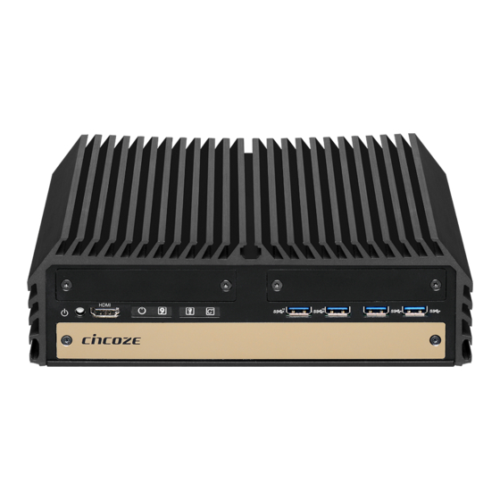
| User’s Manual DX-1000 Series Rugged Workstation 1.6 System I/O 1.6.1 Front ATX Power On/Off Button IGN Setting Switch Press to power-on or power-off the system Used to set up IGN function DisplayPort Port USB 3.0 Port Used to connect the system with DisplayPort Used to connect USB 3.0/2.0/1.1 device monitor AT/ATX Mode Select Switch... -
Page 15: Rear
| User’s Manual DX-1000 Series Rugged Workstation 1.6.2 Rear DC IN Terminal Block Remote Power On/Off Terminal Block Used to plug a DC power input with terminal Used to plug a remote power on/off terminal block block Mic-in Antenna Hole Used to connect a microphone Used to install an antenna jack Line-out... -
Page 16: Mechanical Dimension
| User’s Manual DX-1000 Series Rugged Workstation 1.7 Mechanical Dimension CN-TB-QP22-44_V1.0... -
Page 17: System Pin Definitions And Settings 2.1 Settings
Chapter 2 System Pin Definitions and Settings... -
Page 18: Location Of Connectors , Jumpers And Switches
| User’s Manual DX-1000 Series Rugged Workstation 2.1 Settings When setting the jumpers, ensure that the jumper caps are placed on the correct pins. When the jumper cap is placed on both pins, the jumper is short. If you remove the jumper cap, or place the jumper cap on just one pin, the jumper is open. -
Page 19: Bottom View
| User’s Manual DX-1000 Series Rugged Workstation 2.2.2 Bottom View CN-TB-QP22-44_V1.0... -
Page 20: Connector / Jumper / Switch Definition
| User’s Manual DX-1000 Series Rugged Workstation 2.3 Connector / Jumper / Switch Definition List of Connector / Jumper / Switch Connector Location Definition COM1_1, COM1_2 RS232 / RS422 / RS485 Connector LAN1 and USB3.0 Ports LAN2 and USB3.0 Ports Mini PCI-Express Socket + mSATA + 3G Module CN4, 5, 6 Mini PCI-Express / mSATA Socket... -
Page 21: Definition Of Switches
| User’s Manual DX-1000 Series Rugged Workstation 2.4 Definition of Switches SW1: COM1 / COM2 / COM3 / COM4 Power Select COM1 / 2 / 3 / 4 Voltage Function Setting : Pin Define Switch Location Function DIP1 DIP2 0V(RI) ON (Default) ON (Default) COM1... - Page 22 | User’s Manual DX-1000 Series Rugged Workstation AT_ATX1: AT / ATX Power Mode Switch Definition 1-2 (Left) AT Power Mode 2-3 (Right) ATX Power Mode (Default) CLR_CMOS1: Clear BIOS Switch Definition 1-2 (Left) Normal Status (Default) 2-3 (Right) Clear BIOS CN-TB-QP22-44_V1.0...
-
Page 23: Definition Of Connectors
| User’s Manual DX-1000 Series Rugged Workstation 2.5 Definition of Connectors CN3: Mini PCI-Express Socket (Support mSATA and SIM Card to Link feature) Definition Definition Definition WAKE# RESERVED 3.3V 3.3V USB_D+ RESERVED PERST# 23 PERN0 / SATARP0 41 3.3V 1.5V 3.3V CLKREQ# 25 PERP0 / SATARN0 43... - Page 24 | User’s Manual DX-1000 Series Rugged Workstation CN4 / CN5 / CN6: Mini PCI-Express Socket (Support mSATA feature) Definition Definition Definition WAKE# 3.3V 3.3V USB_D+ 3.3V PERST# 23 PERN0 / SATARP0 41 3.3V 1.5V +3.3VAUX CLKREQ# 25 PERP0 / SATARN0 43 +1.5V REFCLK- SMB_CLK...
- Page 25 | User’s Manual DX-1000 Series Rugged Workstation LED_B1: Power LED Status LED B1 Power LED HDD LED IGN LED TEMP LED Reset1: System Reset Button Button Definition Push Reset System CN1 / CN2: LAN1 / 2 LED Status Definition Act LED Status Definition Link LED Status Definition...
- Page 26 | User’s Manual DX-1000 Series Rugged Workstation POWER1 / 2 / 3 / 4: Power Connector Connector Type: 1x4 4-pin Wafer, 2.0mm pitch Pin 1 Definition +12V FAN1: External PWM Fan Connector PWR_SW2: Power On/Off, SW Switch Connector Type: Terminal Block 1X4 3-pin, 3.5mm pitch Definition Definition...
-
Page 27: Chapter 3 System Setup
Chapter 3 System Setup... -
Page 28: Disassembling The System For Installation
| User’s Manual DX-1000 Series Rugged Workstation 3.1 Disassembling the System for Installation In order to prevent electric shock or system damage, before removing the chassis cover, must turn off power and disconnect the unit from power source. 1. Turn over the unit to have the bottom side face up, loosen the 6 screws of bottom cover and place them aside for later use. - Page 29 | User’s Manual DX-1000 Series Rugged Workstation 3. Loosen the 4 screws. Pull out 4 latches as marked on photo. 4. Hold front and rear panel and lift up the body of unit vertically. CN-TB-QP22-44_V1.0...
- Page 30 | User’s Manual DX-1000 Series Rugged Workstation 5. Turn over the body of the unit and place it gently. CN-TB-QP22-44_V1.0...
-
Page 31: Installing Components On Top Side
| User’s Manual DX-1000 Series Rugged Workstation 3.2 Installing Components on Top Side 3.2.1 Installing the CPU 1. Locate the CPU socket , remove the protection cover on it. 2. Press the CPU socket lever and pull it aside away from the socket to unlock it. Pull back the lever to open the socket. - Page 32 | User’s Manual DX-1000 Series Rugged Workstation 3. Align the notches on CPU with the alignment post on socket. 4. The notches of socket provide the space for fingers while lowering the CPU, hold the CPU by the edges toward the notches and insert the CPU gently. CN-TB-QP22-44_V1.0...
- Page 33 | User’s Manual DX-1000 Series Rugged Workstation 5. Place the thermal pad on the CPU heat spreader. Press down the socket lever to lock the CPU. Thermal pad 6. Align mounting holes of heat sink with the four nut studs. CN-TB-QP22-44_V1.0...
- Page 34 | User’s Manual DX-1000 Series Rugged Workstation 7. Flip the corner of thermal pad and fasten the heat sink with provided 4 screws.(showing as the picture below) CN-TB-QP22-44_V1.0...
-
Page 35: Installing So-Dimm Memory
| User’s Manual DX-1000 Series Rugged Workstation 3.2.2 Installing SO-DIMM Memory 1. Locate the SODIMM socket on the top side of system. 2. Insert a SO-DIMM module at a 45 degree angle until its edge connector is connected to SO-DIMM socket firmly. 45°... -
Page 36: Installing A Mini-Pcie/Msata Card
| User’s Manual DX-1000 Series Rugged Workstation 3.2.3 Installing a Mini-PCIe/mSATA Card 1. Locate the Mini-PCIe slot on the top side of system. 2. Insert the Mini-PCIe card at a 45 degree angle until its edge connector is connected firmly into slot. -
Page 37: Installing Antennas
| User’s Manual DX-1000 Series Rugged Workstation 3.2.4 Installing Antennas Please installing a Mini PCIe Wireless Lan Card on top side before you put on washer and fasten the nut with antenna jack. 1. Remove the antenna rubber covers on rear panel. 2. - Page 38 | User’s Manual DX-1000 Series Rugged Workstation 3. Put on washer and fasten the nut with antenna jack. 4. Assemble the antenna and antenna jack together 5. Attach the RF connector at another end of cable onto the module. CN-TB-QP22-44_V1.0...
-
Page 39: Installing Cfm & Cmi Modules
| User’s Manual DX-1000 Series Rugged Workstation 3.3 Installing CFM & CMI Modules 3.3.1 Installing a CFM-IGN Power Ignition Module 1. Locate the IGN connector on the bottom side of system. 2. Fasten 1 copper pillar before insert IGN module. CN-TB-QP22-44_V1.0... - Page 40 | User’s Manual DX-1000 Series Rugged Workstation 3. Insert IGN module vertically to the female connector on the system’s mainboard, and fasten 2 screws to fix it. CN-TB-QP22-44_V1.0...
-
Page 41: Installing A Cmi-Com Module
| User’s Manual DX-1000 Series Rugged Workstation 3.3.2 Installing a CMI-COM Module 1. Locate the connector of CMI-module on the bottom side of system. 2. Loosen the 2 screws on rear bezel to remove the cover plate CN-TB-QP22-44_V1.0... - Page 42 | User’s Manual DX-1000 Series Rugged Workstation 3. Insert the CMI-COM module carefully into the CMI connector on main board. Fix it with 2 screws. 4. Loosen the 4 D-Sub jack screws as marked on photo. 5. Attach the COM bracket. Fasten 2 screws and 4 D-Sub jack screws to fix it.
-
Page 43: Installing A Cmi-Dio Module
| User’s Manual DX-1000 Series Rugged Workstation 3.3.3 Installing a CMI-DIO Module 1. Locate the connector of CMI-DIO module on the bottom side of system. 2. .Loosen the 2 screws on rear bezel to remove the cover plate CN-TB-QP22-44_V1.0... - Page 44 | User’s Manual DX-1000 Series Rugged Workstation 3. Insert the CMI-DIO module carefully into the CMI connector on main board. Fix it with 2 screws. 4. Attach the DIO bracket, and fasten 2 screws to fix it. CN-TB-QP22-44_V1.0...
-
Page 45: Installing A Cmi-M12 Module
| User’s Manual DX-1000 Series Rugged Workstation 3.3.4 Installing CMI-M12LAN Module Note: The photo example in this section is illustrated by CMI-M12LAN01/UB0910 module as shown in below picture. 1. Loosen the 2 screws on front bezel to remove the cover plate. CN-TB-QP22-44_V1.0... - Page 46 | User’s Manual DX-1000 Series Rugged Workstation 2. Remove 4 rubber rings on M12 jacks; Penetrate M12 jacks of CMI module through the accompanying M12 I/O bracket. then fasten 4 ring hexes onto jacks as illustrated in right hand picture below. Rubber rings 3.
- Page 47 | User’s Manual DX-1000 Series Rugged Workstation 4. Exchange screw to copper pillar before insert the CMI module . 5. Insert the CMI module vertically into the female connector on system’s mainboard until it’s connected firmly and fasten screws to fix it. CN-TB-QP22-44_V1.0...
- Page 48 | User’s Manual DX-1000 Series Rugged Workstation 6. Fasten 2 screws on cover plate. CN-TB-QP22-44_V1.0...
-
Page 49: Installing A Cfm-Poe Module
| User’s Manual DX-1000 Series Rugged Workstation 3.3.5 Installing a CFM-PoE Module 1. Insert the CMI-M12 module vertically into the female connector on system’s mainboard until it’s connected firmly, and fasten 4 copper pillars to fix it. 2. Insert the CFM-PoE module vertically into the female connector on CMI-M12 module vertically. - Page 50 | User’s Manual DX-1000 Series Rugged Workstation 3. Please paste the 2 thermal pads onto the CMI-M12 module carefully. 4. Please paste the heatsink onto the CMI-M12 module carefully. CN-TB-QP22-44_V1.0...
- Page 51 | User’s Manual DX-1000 Series Rugged Workstation 5. Fasten 4 screws to fix it. 6. Please paste the thermal pad onto the heatsink carefully. CN-TB-QP22-44_V1.0...
-
Page 52: Assembling The System
| User’s Manual DX-1000 Series Rugged Workstation 3.4 Assembling the System 3.4.1 Installing Thermal Pad The DX-1000 series don’t need to additional installation of the PCH thermal pad. Note: Thermal pad 3.4.2 Installing Top Cover the 4 1. Hold front and rear panel and put the body of unit back to chassis and fasten screws as marked on photo. -
Page 53: Installing Bottom Cover
| User’s Manual DX-1000 Series Rugged Workstation 3.4.3 Installing Bottom Cover 1. Place the bottom cover back to system. 2. Fasten the bottom cover with 6 screws . CN-TB-QP22-44_V1.0... -
Page 54: Installing Components At Front Side
| User’s Manual DX-1000 Series Rugged Workstation 3.5 Installing Components at Front Side 3.5.1 Removing the Front Cover Plate 1. Loosen 2 screws on front panel to remove cover plate. Note: It’s advised to fasten the 2 screws manually. If fastened with an electrical screw driver, please set the torque of the driver to 2.5KgF. - Page 55 | User’s Manual DX-1000 Series Rugged Workstation 2. Pull the rotating arm and pull the HDD bracket out of system. 3. Make the bottom side of the HDD face up, place the HDD bracket on it. Ensure the direction of bracket is correct and use 4 provided screws to assemble HDD and HDD bracket together. CN-TB-QP22-44_V1.0...
- Page 56 | User’s Manual DX-1000 Series Rugged Workstation 4. Align the HDD bracket assembly with the entrance of removable HDD bay. Holding the rotating arm and insert the HDD bracket until the connector of HDD contact the SATA connector firmly. 5. Place the rotating arm back and fasten the screw. CN-TB-QP22-44_V1.0...
-
Page 57: Installing A Sim Card
| User’s Manual DX-1000 Series Rugged Workstation 3.5.3 Installing a SIM Card 1. Locate the SIM card slot at front side. 2. Insert a SIM card into SIM slot with the gold contacts facing up. Please pay attention to the insert orientation as illustrated. -
Page 58: Installing The Cmos Battery
| User’s Manual DX-1000 Series Rugged Workstation 3.5.4 Installing the CMOS Battery 1. Locate the removable CMOS Battery and loosen the screw. 2. Pull out the CMOS battery bracket with assistance of a tweezer. CN-TB-QP22-44_V1.0... - Page 59 | User’s Manual DX-1000 Series Rugged Workstation 3. Insert a CMOS battery in the battery slot. 4. Insert the battery bracket firmly and fasten the screw. CN-TB-QP22-44_V1.0...
-
Page 60: Fasten The Cover
| User’s Manual DX-1000 Series Rugged Workstation 3.5.5 Fasten the Cover 1. Fasten the cover by using the two screws. 3.5.6 Install an External Fan 1. Prepare an external fan. Loosen the 2 screws halfway on mounting frame before attempting to install it. - Page 61 | User’s Manual DX-1000 Series Rugged Workstation 2. Slide the FAN into the middle groove of chassis as illustrated. Tighten the 2 screws to fix it onto chassis. 3. Move the fan to the center of chassis. Tighten the 2 screws marked on photo to secure it. CN-TB-QP22-44_V1.0...
-
Page 62: Installing The Front Cover Plate
| User’s Manual DX-1000 Series Rugged Workstation 4. Connect the FAN cable to external fan power connector at rear panel. CN-TB-QP22-44_V1.0... -
Page 63: Wall Mount Brackets
| User’s Manual DX-1000 Series Rugged Workstation 3.6 Wall Mount Brackets DX-1000 series offers wall mount brackets that customers can install system on the wall in convenient and economical ways. 1. The mounting holes are at the bottom side of system. Use provided 8 screws to fasten the bracket on each side. -
Page 64: Din-Rail Mount Brackets
| User’s Manual DX-1000 Series Rugged Workstation 3.7 DIN-Rail Mount Brackets DX-1000 series offers DIN-Rail Mount that customer can install system on the DIN Rail. 1. Please refer to section 3.6 Wall Mount Brackets to install mounting bracket at both sides of system. -
Page 65: Vesa Mount
| User’s Manual DX-1000 Series Rugged Workstation 3. Clip the system into DIN rail as illustrated by the following steps. (1) Have lower end of mounting clip snaps into the DIN rail. (2) Press the system toward to have upper end of mounting clip snaps into the other side of DIN rail. - Page 66 | User’s Manual DX-1000 Series Rugged Workstation 1. The following picture illustrates the installation of DX-1000 series on a VESA stand. Align the 4 screw holes of VESA stand with the screw holes on bottom side of system. Fasten 4 screws to fix it.
-
Page 67: Side Mount Brackets
| User’s Manual DX-1000 Series Rugged Workstation 3.9 Side Mount Brackets DX-1000 series offers Side Mount that customer can install system to the right or left side of wall to create effective of space. 1. The mounting holes are at the bottom of system. Fasten the 8 screws to fix the side mount bracket with system together. - Page 68 | User’s Manual DX-1000 Series Rugged Workstation 2. Fasten the screws through the bracket mounting hole to mount system on the wall. CN-TB-QP22-44_V1.0...
-
Page 69: Bios Setup
Chapter 4 BIOS Setup... -
Page 70: Chapter 4 Bios Setup
| User’s Manual DX-1000 Series Rugged Workstation 4.1 BIOS Introduction The BIOS (Basic Input/Output System) is a program located on a Flash Memory on the motherboard. When you start the computer, the BIOS program will gain control. The BIOS first operates an auto-diagnostic test called POST (power on self test) for all the necessary hardware, it detects the entire hardware device and configures the parameters of the hardware synchronization. -
Page 71: Main Setup
| User’s Manual DX-1000 Series Rugged Workstation 4.2 Main Setup Press <Del> key to enter BIOS CMOS Setup Utility, the Main Menu (as shown below) will appears on the screen. Use arrow keys to move among the items and press <Enter> to accept or enter a sub-menu. -
Page 72: Advanced Setup
| User’s Manual DX-1000 Series Rugged Workstation 4.3 Advanced Setup This section allows you to configure and improve your system and allows you to set up some system features according to your preference. 4.3.1 CPU Configuration CN-TB-QP22-44_V1.0... -
Page 73: Sata And Rst Configuration
| User’s Manual DX-1000 Series Rugged Workstation ■ Intel® (VXM) Virtualization Technology Enables or disables Intel® Virtualization Technology, which will allow a platform to run multiple operating systems and applications in independent partitions. With virtualization, one computer system can function as multiple virtual systems. ■... - Page 74 | User’s Manual DX-1000 Series Rugged Workstation ■ Serial ATA Port 0 Port 0 [Enabled] Enables or disables SATA Port 0. Hot Plug [Disabled] Enables or disables Port0 as Hot Pluggable. ■ Serial ATA Port 1 Port 1 [Enabled] Enables or disables SATA Port 1. Hot Plug [Disabled] Enables or disables Port1 as Hot Pluggable.
- Page 75 | User’s Manual DX-1000 Series Rugged Workstation ■ Software Feature Mask Configuration RAID OROM(Option ROM) / RST(Intel® Rapid Storage Technology) driver will refer to the software feature configuration to enable or disable the storage features. HDD Unlock Enables or disables HDD Unlock. LED Locate Enables or disables LED Locate.
-
Page 76: Pch-Fw Configuration
| User’s Manual DX-1000 Series Rugged Workstation 4.3.3 PCH-FW Configuration ■ ME State Enables or disables PCH-FW Configuration ■ Manageability Features State Enables or disables ■ ME Unconfig on RTC Clear Enables or disables ■ Firmware Update Configuration Configure Management Engine Parameters Me FW Image Re-Flash Enables or disables ME firmware Image Re-Flash function. -
Page 77: Acpi Settings
| User’s Manual DX-1000 Series Rugged Workstation 4.3.4 ACPI Settings ■ Enable ACPI Auto Configuration [Disabled] Enables or disables BIOS Advanced Configuration Power Interface® (ACPI) auto configuration. ■ Enable Hibernation [Enabled] Enables or disables system ability to hibernate state (OS/S4 state). This option may not be effective with some OS. -
Page 78: F81866 Super Io Configuration
| User’s Manual DX-1000 Series Rugged Workstation 4.3.5 F81866 Super IO Configuration Set Parameters of Serial Ports. User can Enable/Disable the serial port and Select an optimal settings for the Super IO Device ■ Serial Port 1~6 Configuration. CN-TB-QP22-44_V1.0... -
Page 79: Hardware Monitor
| User’s Manual DX-1000 Series Rugged Workstation Serial Port [Enabled] Enables or disables serial port. Change Settings [Auto] Allows you to change the IO Address & IRQ settings of the specified serial port. Onboard Serial Port 1~6 Mode [RS232] Allows you to select Serial Port Mode. Configuration options: [RS232] [RS422/RS485 Full Duplex] [RS485 Half Duplex] Watch Dog Function You can setup the system watch-dog timer, a hardware timer that generates a reset... -
Page 80: S5 Rtc Wake Settings
| User’s Manual DX-1000 Series Rugged Workstation PC Health Status ■ PWM Fan Function [Enabled] Enables or disables PWM Fan function. 4.3.7 S5 RTC Wake Settings ■ Wake system from S5 [Disabled] Enables or disables wake system from S5 (soft-off state). [Disabled]: Disables wake system from S5. -
Page 81: Serial Port Console Redirection
| User’s Manual DX-1000 Series Rugged Workstation 4.3.8 Serial Port Console Redirection ■ Console Redirection Allow users to enable or disable COM0, COM1, COM2, COM3, COM4, COM5 console redirection function. COM0 = Serial Port 1 COM1 = Serial Port 2 COM2 = Serial Port 3 COM3 = Serial Port 4 COM4 = Serial Port 5... -
Page 82: Network Stack Configuration
| User’s Manual DX-1000 Series Rugged Workstation 4.3.9 Network Stack Configuration ■ Network Stack [Disabled] Enables or disables UEFI Network Stack. 4.3.10 CSM Configuration This option controls legacy/UEFI ROMs priority. CN-TB-QP22-44_V1.0... - Page 83 | User’s Manual DX-1000 Series Rugged Workstation ■ CSM Support [Enabled] Enables or disables compatibility support module. ■ Boot option filter [UEFI and Legacy] Allows you to select which type of operating system to boot. [UEFI and Legacy]: Allows booting from operating systems that support legacy option ROM or UEFI option ROM.
-
Page 84: Usb Configuration
| User’s Manual DX-1000 Series Rugged Workstation 4.3.11 USB Configuration ■ Legacy USB Support [Enabled] This item allows you to enable or disable legacy USB support. When set to [Auto], legacy USB support will be disabled automatically if no USB devices are connected. ■... -
Page 85: Chipset Setup
| User’s Manual DX-1000 Series Rugged Workstation 4.4 Chipset Setup This section allows you to configure chipset related settings according to user’s preference. 4.4.1 System Agent (SA) Configuration CN-TB-QP22-44_V1.0... -
Page 86: Pch-Io Configuration
| User’s Manual DX-1000 Series Rugged Workstation ■ VT-d [Enabled] Enables or disables Intel® Virtualization Technology for Directed I/O (VT-d) capability. ■ Above 4GB MMIO BIOS assignment [Diabled] Enables or disables Above 4GB Memory Mapped IO BIOS assignment. This is disabled automatically when Aperture Size is set to 2048MB. - Page 87 | User’s Manual DX-1000 Series Rugged Workstation ■ PCI Express Configuration PCI Express (Mini PCIe1 (CN3)) PCI Express (Mini PCIe1 (CN3)) [Enabled] Enables or disables PCI Express Root Port. PCIeSpeed [Auto] Allows you to select PCI Express port speed. Configuration options: [Auto] [Gen1] [Gen2] [Gen3]. PCI Express (Mini PCIe1 (CN4)) PCI Express (Mini PCIe1 (CN4)) [Enabled] Enables or disables PCI Express Root Port.
- Page 88 | User’s Manual DX-1000 Series Rugged Workstation ■ LAN i219LM Controller [Enabled] Enables or disables i219LM LAN Controller. ■ Wake on LAN Enabled [Enabled] Enables or disables integrated LAN Wake On LAN function. ■ LAN i210AT Controller [Enabled] Enables or disables i210AT LAN Controller. ■...
-
Page 89: Security Setup
| User’s Manual DX-1000 Series Rugged Workstation 4.5 Security Setup This section allows you to configure BIOS security settings. 4.5.1 Administrator Password Allows you to set Administrator Password to control access to the BIOS Setup utility. 4.5.2 User Password Allows you to set User Password to control access to the system at boot and to the BIOS Setup utility. -
Page 90: Boot Setup
| User’s Manual DX-1000 Series Rugged Workstation 4.6 Boot Setup This section allows you to configure Boot settings. 4.6.1 Setup Prompt Timeout Use this item to set number of seconds (1..65535) to wait for setup activation key. 4.6.2 Bootup NumLock State Allows you to set NumLock key to [On] or [Off] state when system boots up. -
Page 91: Save & Exit
| User’s Manual DX-1000 Series Rugged Workstation 4.7 Save & Exit 4.7.1 Save Changes and Exit This item allows you to exit system setup after saving changes. 4.7.2 Discard Changes and Exit This item allows you to exit system setup without saving changes. 4.7.3 Save Changes and Reset This item allows you to reset the system after saving changes. - Page 92 Chapter 5 Product Application (For DIO only)
-
Page 93: Chapter 5 Product Application
| User’s Manual DX-1000 Series Rugged Workstation This chapter describes the DIO applications . 5.1 Digital I/O (DIO) Application This section describes DIO application of the product. The content and application development are better understood and implemented by well experienced professionals or developers. 5.1.1 Digital I/O Programming Guide 5.1.1.1 Pins for Digital I/O Item... - Page 94 | User’s Manual DX-1000 Series Rugged Workstation 5.1.1.3 Relative Registers To program the F81866A configuration registers, the following configuration procedures. CN-TB-QP22-44_V1.0...
- Page 95 | User’s Manual DX-1000 Series Rugged Workstation CN-TB-QP22-44_V1.0...
- Page 96 | User’s Manual DX-1000 Series Rugged Workstation 5.1.1.4 Sample Code in C Language 5.1.1.4.1 Control of GP70 to GP77 (DI1 ~ DI8) #define AddrPort 0x4E #define DataPort 0x4F <Enter the Extended Function Mode> WriteByte(AddrPort, 0x87) WriteByte(AddrPort, 0x87) //Must write twice to entering Extended mode <Select Logic Device>...
- Page 97 // Select configuration register 60h (High Byte address) WriteByte(DataPort, ( 0x0A)) WriteByte(AddrPort, 0x61) // Select configuration register 61h (Low Byte address) WriteByte(DataPort, ( 0x00)) <Leave the Extended Function Mode> WriteByte(AddrPort, 0xAA) Cincoze default DIO Port base address is set to 0x0A00h CN-TB-QP22-44_V1.0...
- Page 98 | User’s Manual DX-1000 Series Rugged Workstation 5.1.1.5 DATA Bit Table (DIO) 7 6 5 4 3 2 1 0 = DI1 0 0 0 0 0 0 0 1 Value (Base address +3) (0xA03) 7 6 5 4 3 2 1 0 = DI2 0 0 0 0 0 0 1 0 Value...
- Page 99 | User’s Manual DX-1000 Series Rugged Workstation 7 6 5 4 3 2 1 0 = DO1 0 0 0 0 0 0 0 1 Value (Base address +2) (0xA02) 7 6 5 4 3 2 1 0 = DO2 0 0 0 0 0 0 1 0 Value (Base address +2) (0xA02)
-
Page 100: Dio) Hardware Specification
| User’s Manual DX-1000 Series Rugged Workstation 5.1.1.6 DIO I/O Port Address (Default Address 0xA00) Pin Definition Data Bits Digital Input 0xA03 I/O Port address Pin Definition Data Bits Digital Output 0xA02 I/O Port address 5.2 (DIO) Hardware Specification • XCOM+ : Isolated power in V+ •... -
Page 101: Dio Connector Definition
| User’s Manual DX-1000 Series Rugged Workstation 5.2.1 DIO Connector Definitions DIO1: Digital Input Connector Connector Type: Terminal Block 1X10 10-pin, 3.5mm pitch Definition XCOM+ XCOM- Pin 1 DIO2: Digital Output Connector Connector Type: Terminal Block 1X10 10-pin, 3.5mm pitch Definition XCOM+ XCOM-... -
Page 102: Chapter 6 Optional Module Pin Definitions And Settings
Chapter 6 Optional Module Pin Definitions and Settings... -
Page 103: Cfm-Ign Power Ignition Module Connector Location
| User’s Manual DX-1000 Series Rugged Workstation 6.1 Location of the Connectors and Switches Model No. Description CFM-IGN01 CFM Module with Power Ignition Sensing Control Function, Select 12V/24V CMI-COM01/UB0903 CMI Module with 2x RS232/422/485, 1x Universal Bracket CMI-DIO01/UB0918 CMI Module with 16x Optical Isolated DIO (8 in/8 out), 1x Universal Bracket 6.2 CFM-IGN Power Ignition Module Connector Location SW2: IGN Function Switch Set shutdown delay timer when ACC is turned off... -
Page 104: Cmi-Com Module Connector Definition And Settings
| User’s Manual DX-1000 Series Rugged Workstation and Settings 6.3 CMI-COM Module Connector Definition COM5 / COM6: RS232 / RS422 / RS485 Connector Connector Type: 9-pin D-Sub COM5 / COM6 RS422 / 485 RS485 RS232 Full Duplex Half Duplex Definition Definition Definition DATA-... -
Page 105: Cmi-M12 Lan Module Pin Definitions
| User’s Manual DX-1000 Series Rugged Workstation 6.4 CMI-M12 LAN Module Pin Definitions Connector Type: M12 A coded 8pin connector Definition Definition 2_LAN1_0+ 2_LAN1_0- 2_LAN1_1+ 2_LAN1_2+ 2_LAN1_2- 2_LAN1_1- 2_LAN1_3+ 2_LAN1_3- 6.5 CMI-M12 PoE Module Pin Definitions Connector Type: M12 A coded 8pin connector POE type: Midspan (B-Type) Definition Definition 2_LAN1_0+... - Page 106 © 2017 Cincoze Co., Ltd. All rights reserved. The Cincoze logo is a registered trademark of Cincoze Co., Ltd. All other logos appearing in this catalog are the intellectual property of the respective company, product, or organization associated with the logo.
Need help?
Do you have a question about the DX-1000-R10 and is the answer not in the manual?
Questions and answers