Sign In
Upload
Download
Table of Contents
Contents
Add to my manuals
Delete from my manuals
Share
URL of this page:
HTML Link:
Bookmark this page
Add
Manual will be automatically added to "My Manuals"
Print this page
×
Bookmark added
×
Added to my manuals
Manuals
Brands
Cincoze Manuals
Desktop
DS-1100 Series
User manual
Cincoze DS-1100 Series User Manual
Rugged workstation, 7/6th generation intel core i3/i5/i7 (kaby lake-s/skylake-s) high performance, modular and expandable rugged embedded computer
Hide thumbs
Also See for DS-1100 Series
:
User manual
(112 pages)
1
Table Of Contents
2
3
4
5
6
7
8
9
10
11
12
13
14
15
16
17
18
19
20
21
22
23
24
25
26
27
28
29
30
31
32
33
34
35
36
37
38
39
40
41
42
43
44
45
46
47
48
49
50
51
52
53
54
55
56
57
58
59
60
61
62
63
64
65
66
67
68
69
70
71
72
73
74
75
76
77
78
79
80
81
82
83
84
85
86
87
88
89
90
91
92
93
94
95
96
97
98
99
100
101
102
103
104
105
106
107
108
109
110
page
of
110
Go
/
110
Contents
Table of Contents
Bookmarks
Table of Contents
Table of Contents
Acknowledgement
Copyright Notice
Declaration of Conformity
Disclaimer
Revision
Product Warranty Statement
Technical Support and Assistance
Conventions Used in this Manual
Safety Precaution
Optional Modules & Accessories
Ordering Information
Package Contents
Chapter 1 Product Introductions
Overview
Highlights
Product Pictures
Key Features
Hardware Specification
System I/O
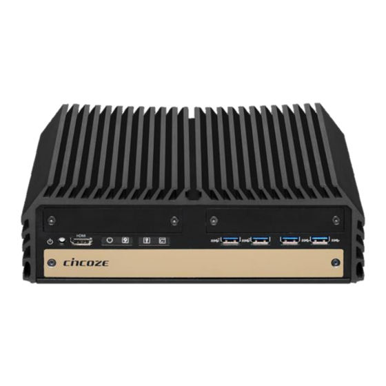
Front
Rear
Mechanical Dimension
Chapter 2 Switches and Connectors
Location of Switches and Connectors
Top View
Bottom View
Switches and Connectors Definition
Definition of Switches
Definition of Connectors
Chapter 3 System Setup
Removing the Top Cover
Installing CPU
Installing SO-DIMM Memory
Installing a Mini-Pcie/Msata Card on Top Side
Installing a Mini-Pcie/Msata Card on Bottom Side
Installing Antennas
Installing a SATA Hard Drive on Top Side
Installing a Low Speed CMI Module
Installing a High Speed CMI Module
Installing a CFM-IGN Power Ignition Module
Installing the Internal FAN (for DS-1102 Only)
Installing a Pci/Pcie Add-On Card (for DS-1101 and DS-1102 Only)
Assembling the System
Installing a SATA Hard Drive at Front Side
Installing a SIM Card
Installing the CMOS Battery
Fastening the Cover
Installing an External Fan
Wall Mount Brackets
Chapter 4 BIOS Setup
BIOS Introduction
Main Setup
System Date
System Time
Advanced Setup
ACPI Settings
AMT Configuration
PCH-FW Configuration
F81866 Super IO Configuration
Hardware Monitor
S5 RTC Wake Settings
Serial Port Console Redirection
CPU Configuration
SATA Configuration
PCI Subsystem Settings
CSM Configuration
USB Configuration
Chipset Setup
System Agent (SA) Configuration
PCH-IO Configuration
Security Setup
Administrator Password
User Password
Security Boot
Boot Setup
Setup Prompt Timeout
Bootup Numlock State
Quiet Boot
Fast Boot
Save & Exit
Save Changes and Exit
Discard Changes and Exit
Save Changes and Reset
Discard Changes and Reset
Save Changes
Discard Changes
Restore Defaults
Save as User Defaults
Restore User Defaults
Chapter 5 Product Application (for DIO Only)
Digital I/O (DIO) Application
Digital I/O Programming Guide
Digital I/O (DIO) Hardware Specification
CMI-CD, CMI-ICD Connector Definition
Advertisement
Quick Links
Download this manual
DS-1100 Series
User Manual
Rugged Workstation
7/6th Generation Intel® Core™ i3 / i5 / i7 (Kaby Lake-S/
Skylake-S) High Performance, Modular and Expandable
Rugged Embedded Computer
Version: V2.34
Table of
Contents
Previous
Page
Next
Page
1
2
3
4
5
Advertisement
Table of Contents
Need help?
Do you have a question about the DS-1100 Series and is the answer not in the manual?
Ask a question
Questions and answers
Related Manuals for Cincoze DS-1100 Series
Desktop Cincoze DS-1100 Series User Manual
6th generation intel core i3 / i5 / i7 (skylake-s) high performance, modular and expandable rugged embedded computer (112 pages)
Desktop Cincoze DS-1102-R20 User Manual
Rugged workstation, 7/6th generation intel core i3/i5/i7 (kaby lake-s/skylake-s) high performance, modular and expandable rugged embedded computer (110 pages)
Desktop Cincoze DS-1400 Series User Manual
Rugged embedded computer, 12th generation intel core series processors, high performance, expandable and modular rugged embedded computer (127 pages)
Desktop Cincoze DS-1401 User Manual
Rugged embedded computer, 12th generation intel core series processors, high performance, expandable and modular rugged embedded computer (127 pages)
Desktop Cincoze DS-1402 User Manual
Rugged embedded computer, 12th generation intel core series processors, high performance, expandable and modular rugged embedded computer (127 pages)
Desktop Cincoze DC-1100 Series User Manual
Fanless computing solution (74 pages)
Desktop Cincoze DX-1100 Series User Manual
9/8th generation intel xeon and core processors, extreme performance, compact and modular rugged workstation (104 pages)
Desktop Cincoze DA-1100 Series User Manual
Intel pentium n4200/ celeron n3350 processoraffordable fanless embedded computer (85 pages)
Desktop Cincoze DC-1200 Series User Manual
Fanless computing solution, intel pentium n4200 processor compact fanless embedded computer (103 pages)
Desktop Cincoze DC-1200 Series User Manual
Rugged embedded computer (111 pages)
Desktop Cincoze DA-1000 Series User Manual
Fanless computing solution (75 pages)
Desktop Cincoze DI-1100 Series User Manual
Rugged embedded computer compact, high performance, modular embedded computer with 8th gen intel core u cpu (whiskey lake) (115 pages)
Desktop Cincoze DV-1000 Series User Manual
(123 pages)
Desktop Cincoze DX-1200 User Manual
Rugged embedded computer (121 pages)
Desktop Cincoze DI-1200 Series User Manual
Rugged embedded computer (98 pages)
Desktop Cincoze DV-1100 User Manual
13/12th gen. intel® core™ series high performance and basic function rugged embedded computer (92 pages)
This manual is also suitable for:
Ds-1100-r20
Ds-1101-r20
Ds-1102-r20
Ds-1102
Ds-1101
Ds-1100
Table of Contents
Print
Rename the bookmark
Delete bookmark?
Delete from my manuals?
Login
Sign In
OR
Sign in with Facebook
Sign in with Google
Upload manual
Upload from disk
Upload from URL


Need help?
Do you have a question about the DS-1100 Series and is the answer not in the manual?
Questions and answers